posted 09 January 2019,
In my previous post on this subject I described the components I planned to use for my Digital Tension Scale project, and also the design for a box that would mount directly on the S-shaped load cell assembly.
This post describes the ‘final’ (to the extent than anything I do can be considered final) assembly of the completed system into my 3D-printed housing, and the results of some initial battery-powered testing.
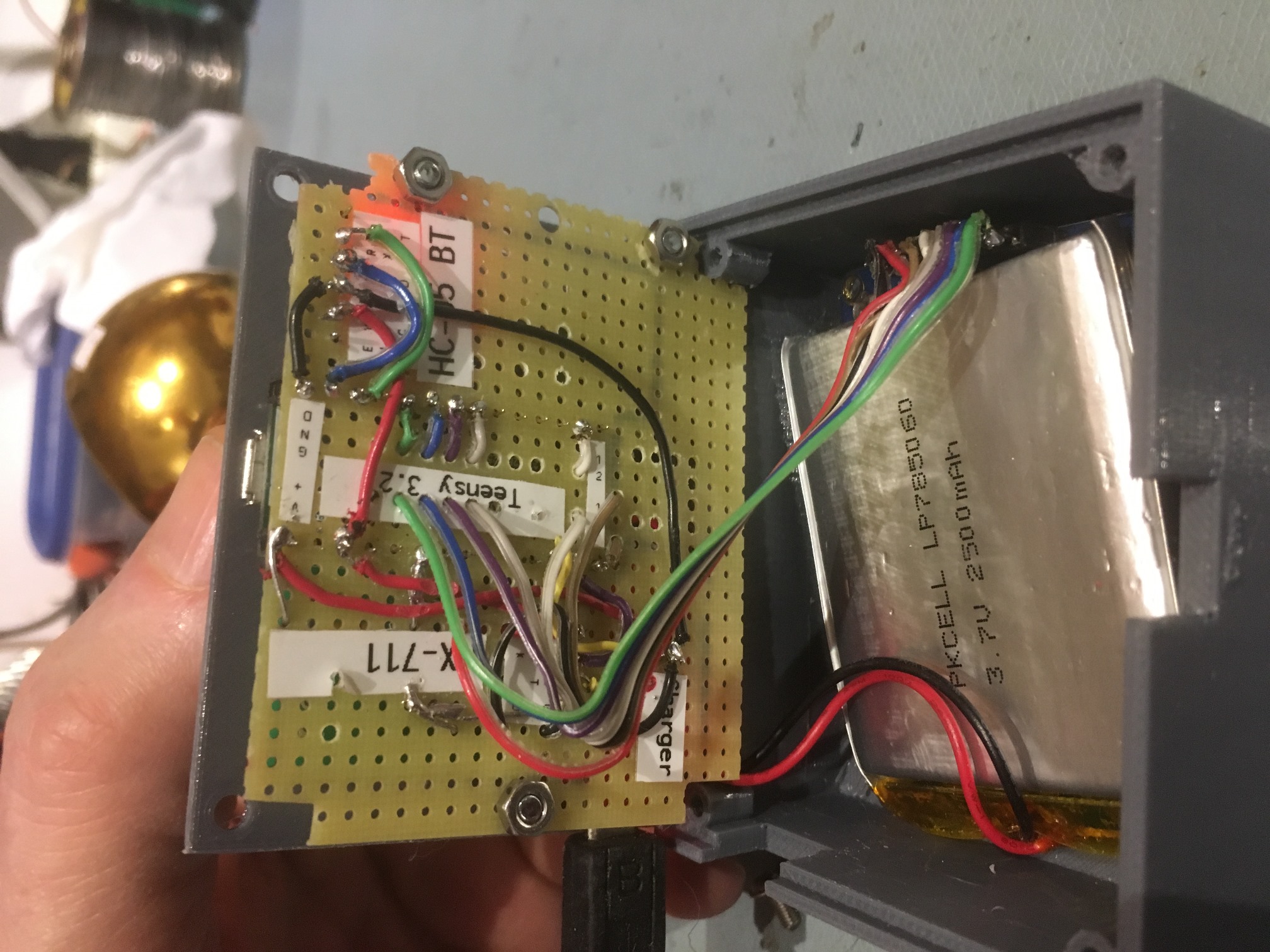
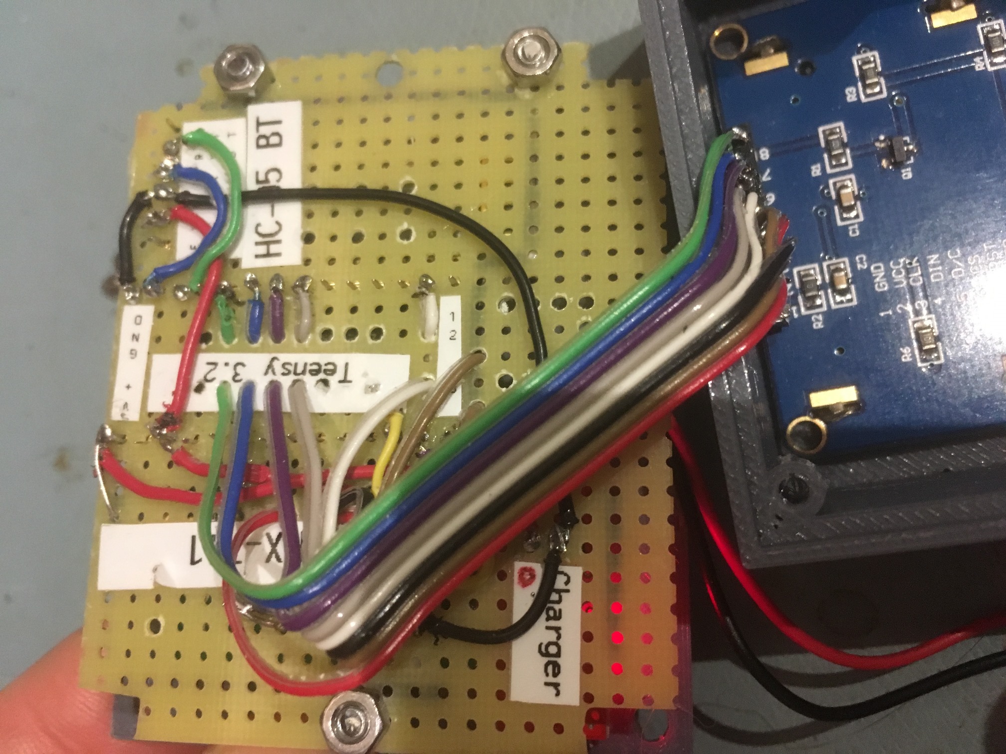
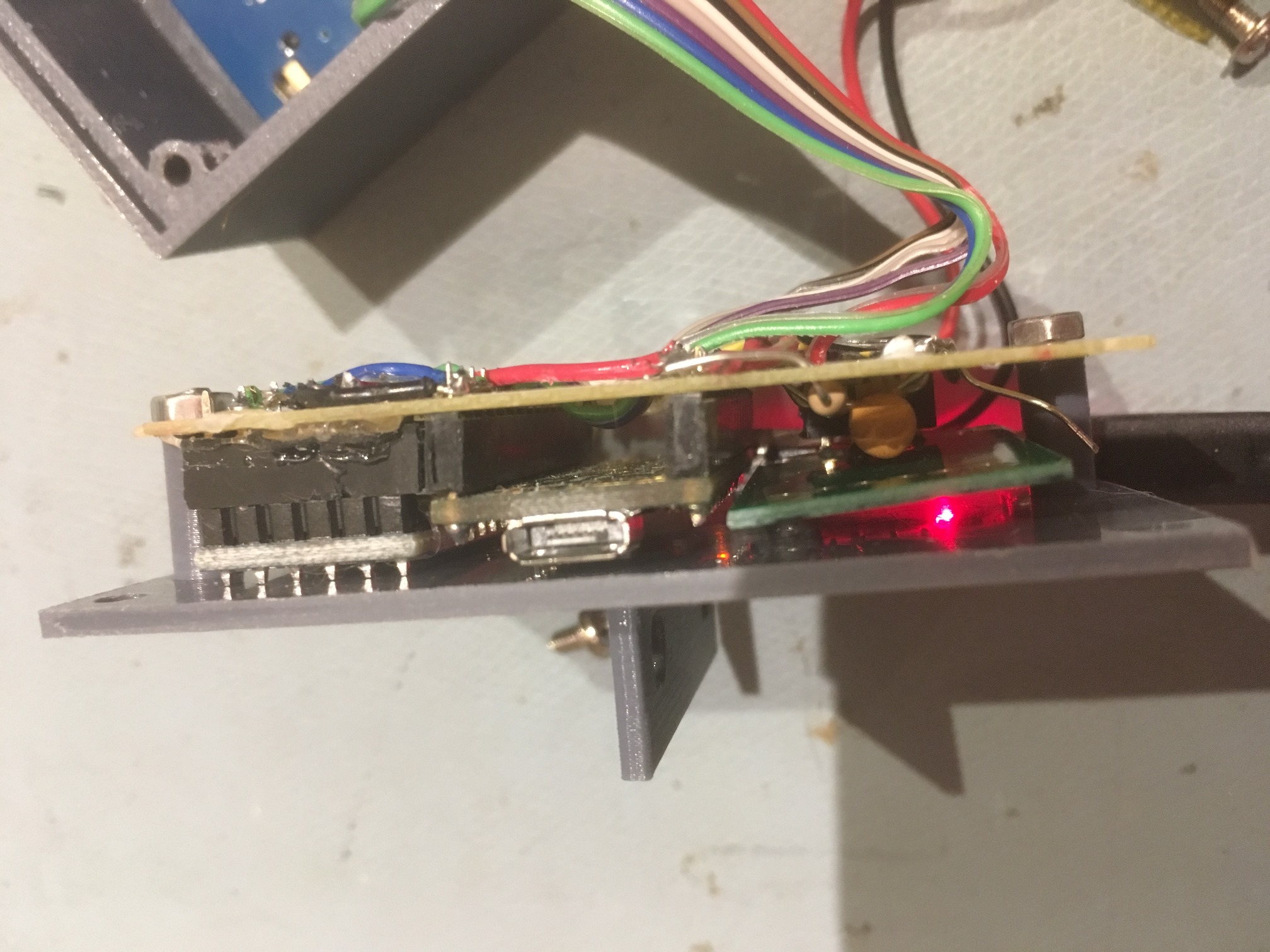
As shown in the following photos, the major components (Teensy 3.2 microcontroller, HC-05 Bluetooth Module, HX-711 load cell amp/A-D, and Sparkfun ‘Basic’ LiPo Charger) were mounted on perfboard, which was then in turn attached to the box lid via a set of custom-printed standoffs. A short piece of ribbon cable connects the Teensy to the LCD display. The general idea behind this physical layout is to allow easy access to the electronics for troubleshooting, and to allow for battery charging and/or Teensy programming without having to open the box.
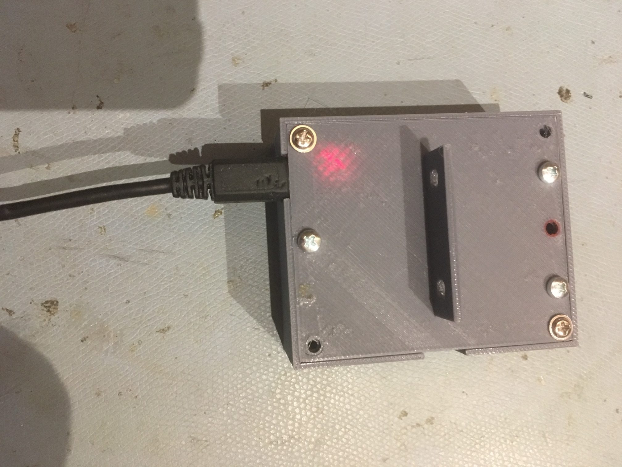
3D-printed housing. Note the glow from the Sparkfun charger LED
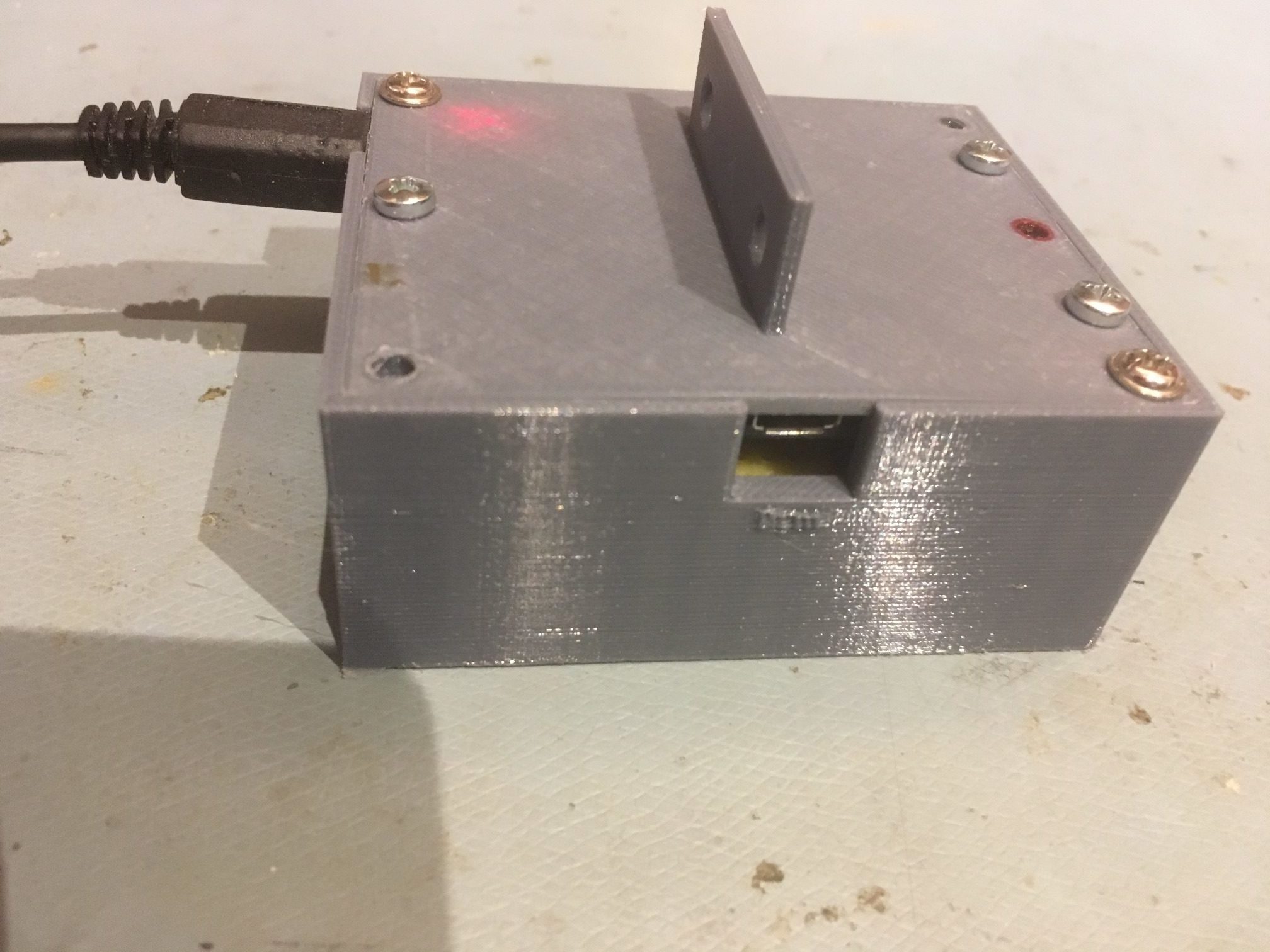
View of housing showing the access port for supplying USB power and/or programming the Teensy
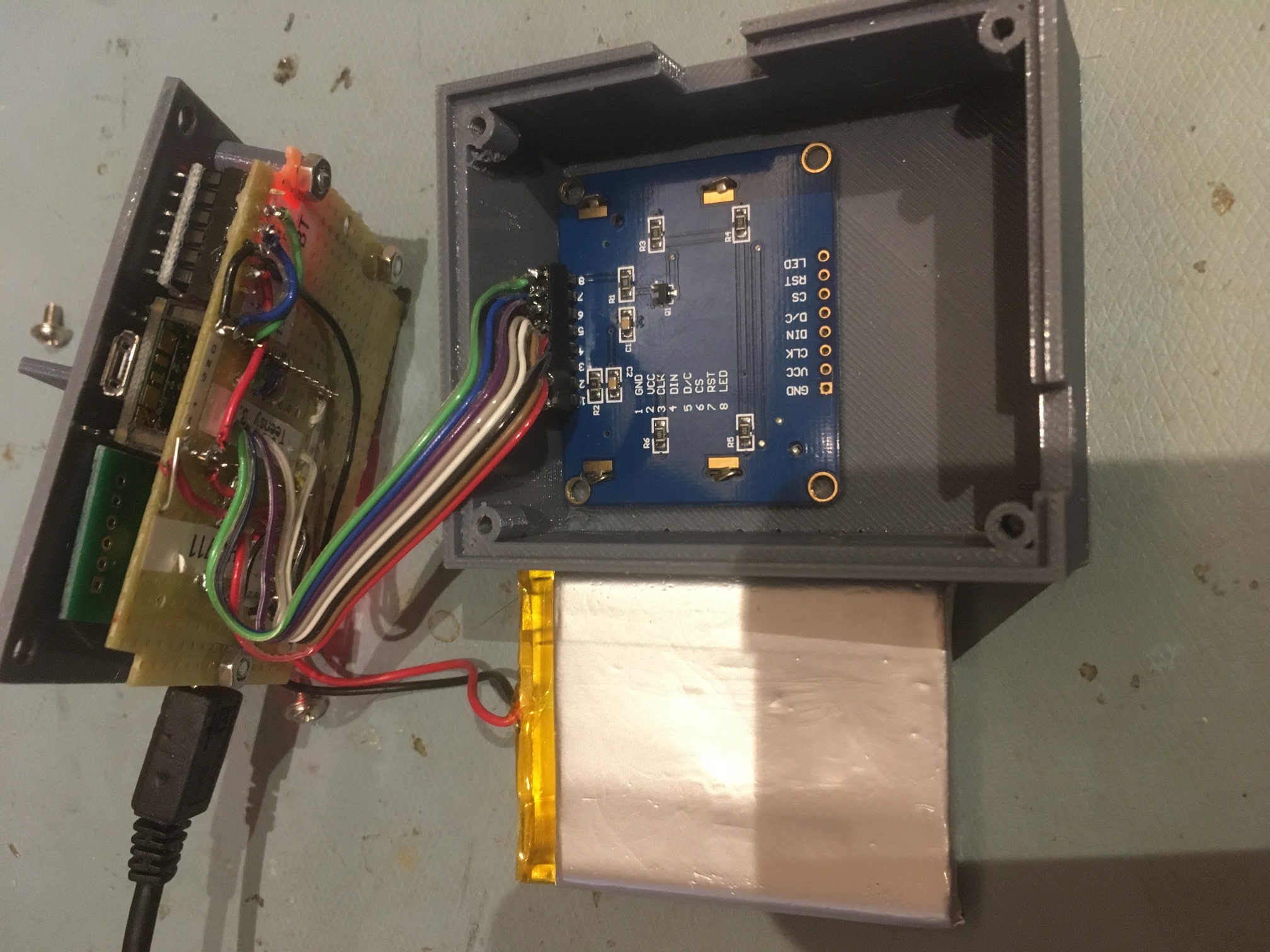
View with the lid and electronics board removed. The LCD display is face down in its cutout
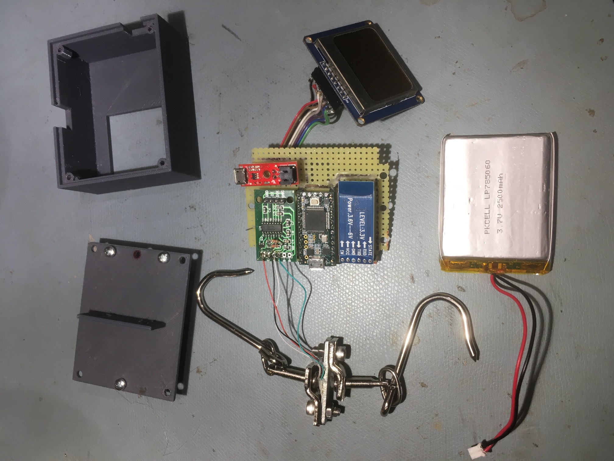
Exploded view showing all system components
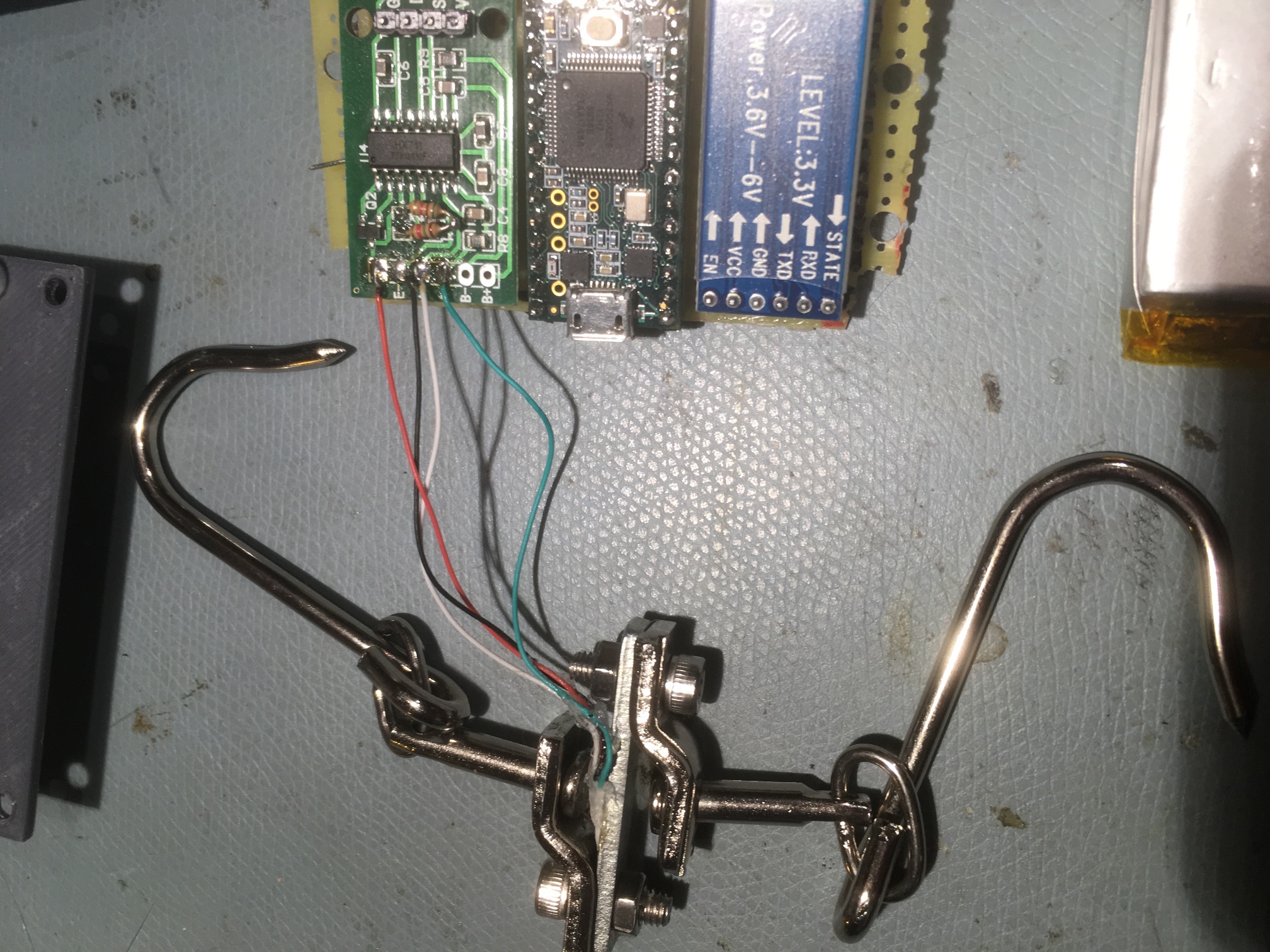
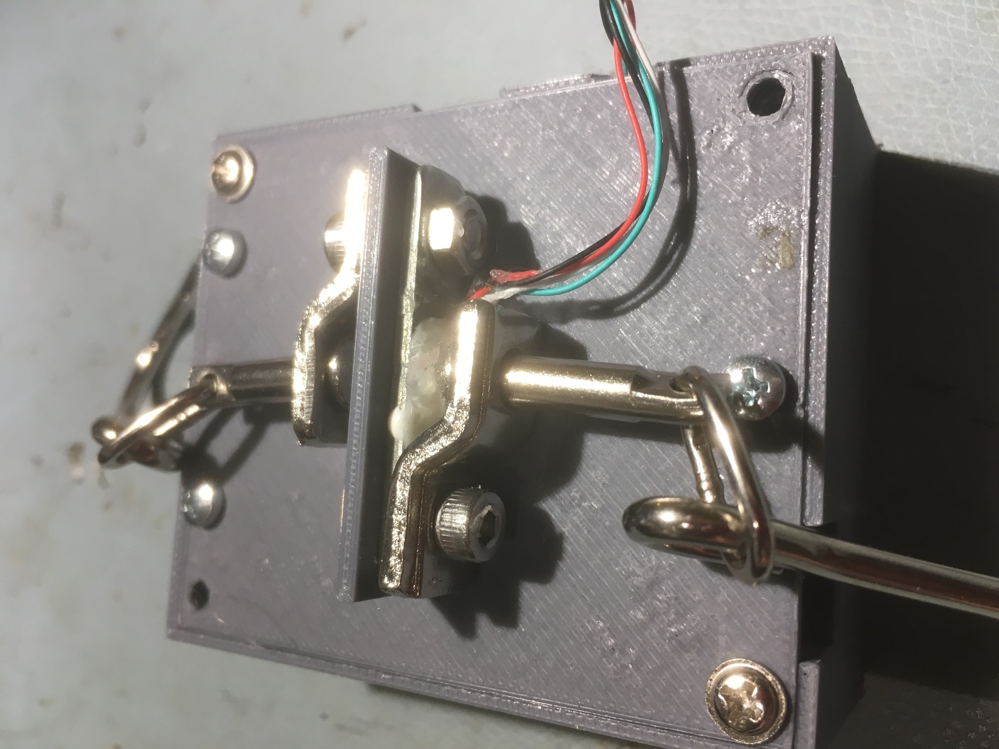
Showing connections from load cell to HX-711
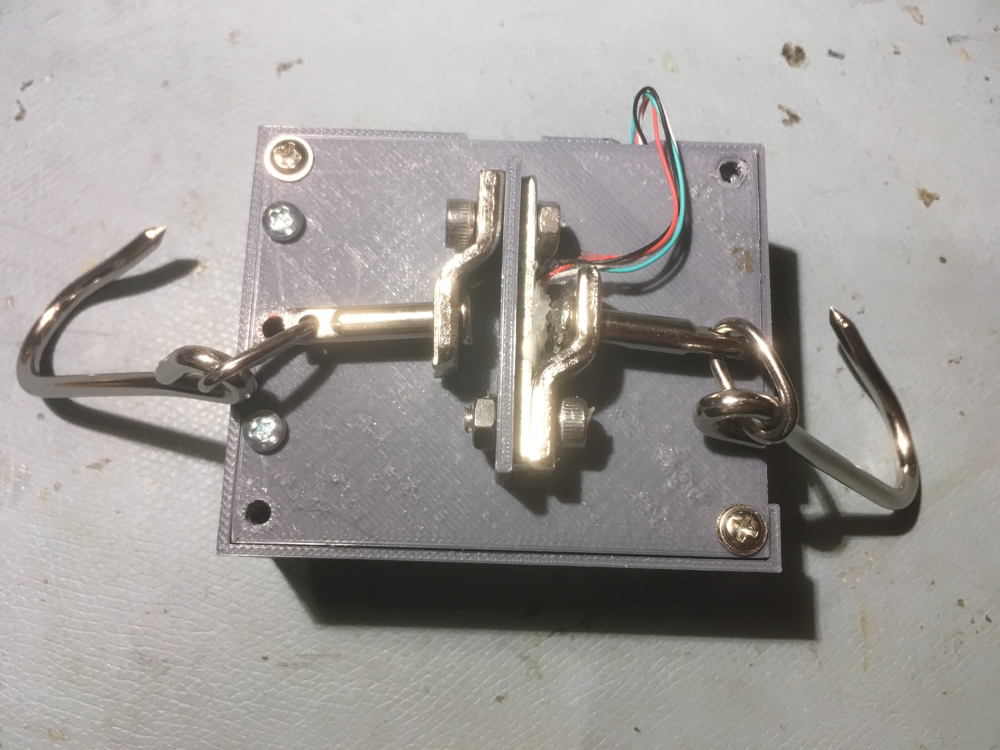
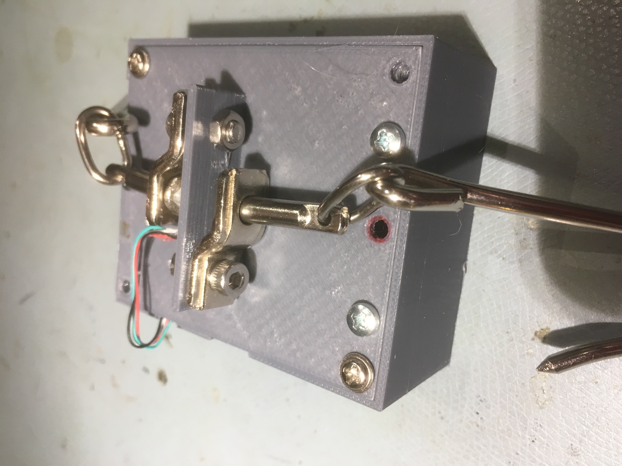
Top view showing how load cell attaches to the housing
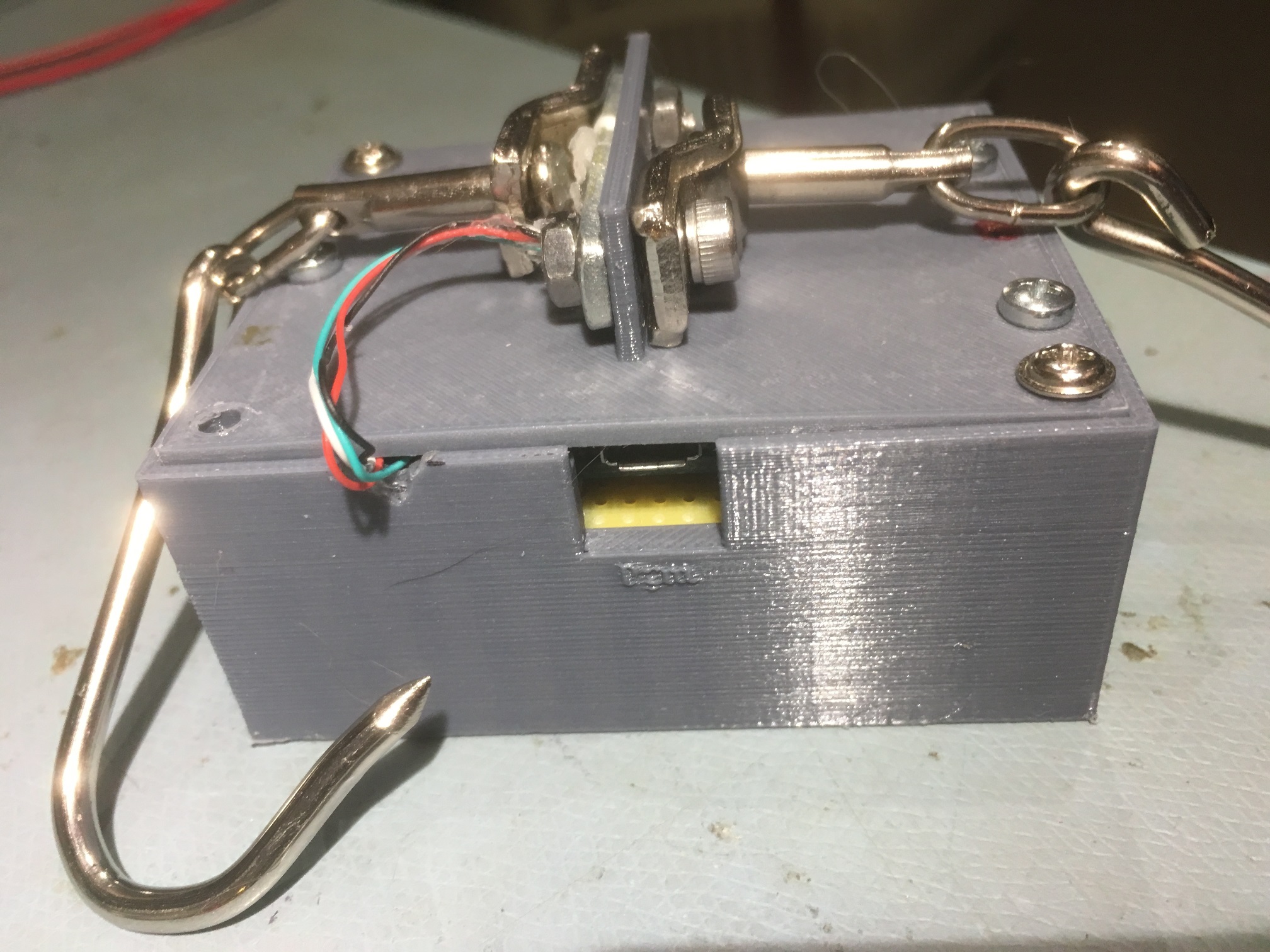
Closeup showing load cell lead routing and power/programming port
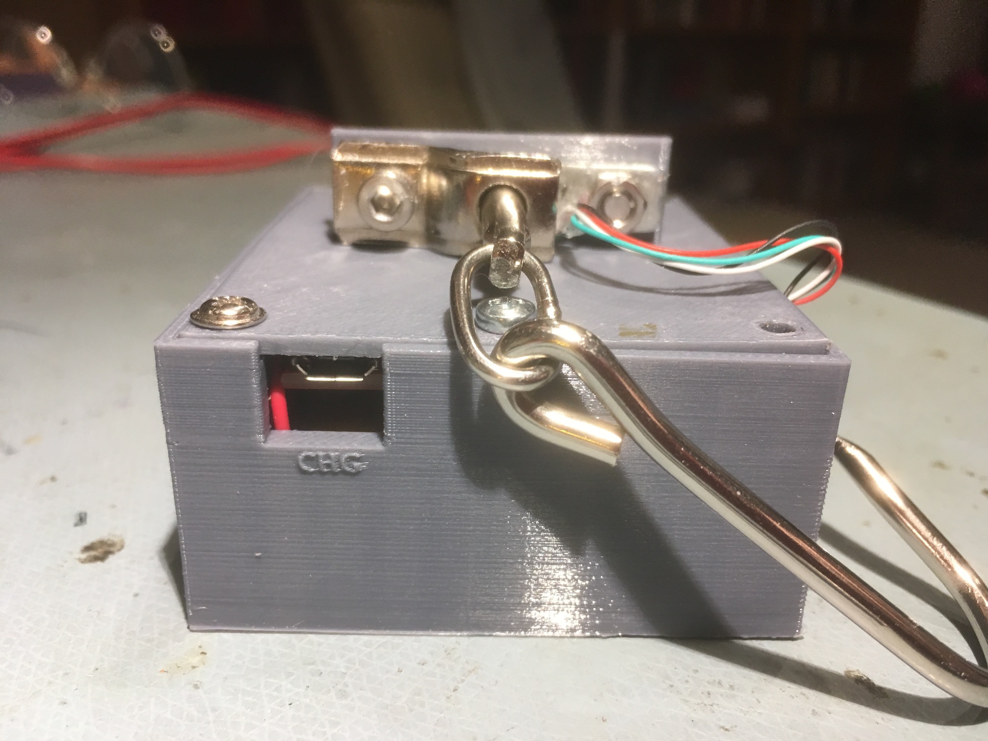
End view showing charging port
Preliminary Testing Results:
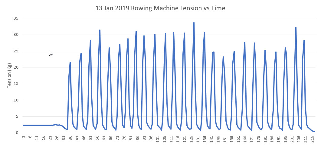
At this point I have everything running on battery power only inside the box, and I have been able to demonstrate remote data capture on my PC using the HC-05 BT link. The following image shows the data taken from my rowing machine, and a short video demonstrating the setup.
Complete Code:
Here is the complete Teensy 3.2 program as it stands today. As you can see if you inspect the code, I have the Teensy low-power stuff turned OFF for the moment (that’s the purpose of the ‘#define NO_SNOOZE’ statement.
|
1 2 3 4 5 6 7 8 9 10 11 12 13 14 15 16 17 18 19 20 21 22 23 24 25 26 27 28 29 30 31 32 33 34 35 36 37 38 39 40 41 42 43 44 45 46 47 48 49 50 51 52 53 54 55 56 57 58 59 60 61 62 63 64 65 66 67 68 69 70 71 72 73 74 75 76 77 78 79 80 81 82 83 84 85 86 87 88 89 90 91 92 93 94 95 96 97 98 99 100 101 102 103 104 105 106 107 108 109 110 111 112 113 114 115 116 117 118 119 120 121 122 123 124 125 126 127 128 129 130 131 132 133 134 135 136 137 138 139 140 141 142 143 144 145 146 147 148 149 150 151 152 153 154 155 156 157 158 159 160 161 162 163 164 165 166 167 168 169 170 171 172 173 174 175 176 177 178 179 180 181 182 183 184 185 186 187 188 189 190 191 192 193 194 195 196 197 198 199 200 201 202 203 204 205 206 207 208 209 210 211 212 213 214 215 216 217 218 219 220 221 222 223 224 225 226 227 228 229 230 231 232 233 234 235 236 237 238 239 240 241 242 243 244 245 246 247 248 249 250 251 252 253 254 255 256 257 258 259 260 261 262 263 264 265 266 267 268 269 270 271 272 273 274 275 276 277 278 279 280 281 282 283 284 285 286 287 288 289 290 291 292 293 294 295 296 297 298 299 300 301 302 303 304 305 306 307 308 309 310 311 312 313 314 315 316 317 318 319 320 321 322 323 324 325 326 327 328 329 330 331 332 333 334 335 336 337 338 339 340 341 342 343 344 345 346 347 348 349 350 351 352 353 354 355 356 357 358 359 360 361 362 363 364 365 366 367 368 369 370 371 372 373 374 375 376 377 378 379 380 381 382 383 384 385 386 387 388 389 390 391 392 393 394 395 396 397 398 399 400 401 402 403 404 405 406 407 408 409 410 411 412 413 414 415 416 417 418 419 420 421 422 423 424 425 426 427 428 429 430 431 432 433 434 435 436 437 438 439 440 441 442 443 444 445 446 447 448 449 450 451 452 453 454 455 456 457 458 459 460 461 462 463 464 465 466 467 468 469 470 471 472 473 474 475 476 477 478 479 480 481 482 483 484 485 486 487 488 489 490 491 492 493 494 495 496 497 498 499 500 501 502 503 504 505 506 507 508 509 510 511 512 513 514 515 516 517 518 519 520 521 522 523 524 525 526 527 528 529 530 531 532 533 534 535 536 537 538 539 540 541 542 543 544 545 546 547 548 549 550 551 552 553 554 555 556 557 558 559 560 561 562 563 564 565 566 567 568 569 570 571 572 573 574 575 576 577 578 579 580 581 582 583 584 585 586 587 |
/* Name: TeensyLowPowerDigitalScale.ino Created: 12/2/2018 9:43:43 PM Author: FRANKWIN10\Frank */ //12/27/18 Added bluetooth support via Serial1 //12/27/18 Added calibration code from TeensyDigitalCalibration.ino /* Name: DigitalScaleAutoCal.ino Created: 11/15/2018 4:49:12 PM Author: FRANKWIN10\Frank This program is a modification of the November 2016 circuits4you.com program for interfacing with the HX711 Module coupled with a typical load cell. It's purpose is to automatically calibrate the combination to accurately display weight in Kg. The process is as follows: Step1: User opts to calibrate by entering 'Y' at the prompt. Entering any other key (or just letting the question time out) will skip the calibration process Step2: User establishes 'tare' weight physical configuration with any non-measured weight attached (in my case, the bucket used to hold measured amounts of water used for weight calibration), and then presses 'T' to zero out the 'tare weight' Step3: The user establishes a calibration weight condition (in my case, 1.8 liters of water) and enters the weight value (in Kg). The program then calculates the scale factor needed to calibrate the scale for the entered weight and then automatically drops into measurement mode Step5: The user enters 'q' to quit measurements. */ /* I need to combine the calibration code from TeensyDigitalScaleCalibration.ino with this program, so I can run the cal procedure by sending a character or two from my PC or phone. No character, no calibration. */ #pragma region DEBUG_DEFINES #define NO_SNOOZE #pragma endregion Debugging Defines #pragma region CAL_SUPPORT #include <elapsedMillis.h> elapsedMillis sinceLastWaitMsg; const int WAITINGMSGINTERVALMSEC = 1000; //1-sec intervals const int MAX_WAITING_INTERVALS = 10; //how long to wait before starting measurement const int BUFLEN = 20; int numWaitIntervals = 0; char inbuf[BUFLEN]; //buffer for user input char inbuf1[BUFLEN];//buffer for serial1 input //Change this calibration factor as per your load cell once it is found. You many need to vary it in thousands bool bDoneMeasuring = false; const char* waitstr = "Waiting...Measurements will start in "; #pragma endregion Calibration Support #include <SPI.h> #include <Adafruit_GFX.h> #include <Adafruit_PCD8544.h> #pragma region LOW_POWER_SUPP //12/03/18 added for low power mode #include <Snooze.h> // Load just the 'timer' wake-up driver SnoozeTimer timer; SnoozeUSBSerial usb; SnoozeBlock config_teensy32(usb, timer); const int SLEEP_TIME_MSEC = 5000; const float INACTIVE_SCALE_THRESHOLD_KG = 1.f; //const float INACTIVE_SCALE_THRESHOLD_KG = -10.f; //const int MIN_INACTIVE_SCALE_COUNT = 100; const int MIN_INACTIVE_SCALE_COUNT = 20; const int BLUETOOTH_POWER_PIN = 12; int numInactiveScaleCounts = 0; #pragma endregion Low Power Support #pragma region LOAD_CELL #include "HX711.h" //You must have this library in your arduino library folder #include <EEPROM.h> #include<EEPROMAnything.h> //so I can read the last calibration value from EEPROM #define DOUT A1 #define CLK A0 HX711 scale(DOUT, CLK); //Change this calibration factor as per your load cell once it is found. You many need to vary it in thousands long calibration_factor = -96650; //-106600 worked for my 40Kg max scale setup long tare_offset = 0; const int LED_PIN = 13; const int CAL_FACTOR_EEPROM_ADDR = 0; const int TARE_OFFSET_EEPROM_ADDR = CAL_FACTOR_EEPROM_ADDR + sizeof(calibration_factor); float scaleKg = 0; float vBatt = 0; #pragma endregion Load Cell Support #pragma region LCD_DISPLAY // Hardware SPI (faster, but must use certain hardware pins): // Note with hardware SPI MISO and SS pins aren't used but will still be read // and written to during SPI transfer. Be careful sharing these pins! // SCK is LCD serial clock (SCLK) - this is pin 13 on Arduino Uno // MOSI is LCD DIN - this is pin 11 on an Arduino Uno // pin 6 - Data/Command select (D/C) // pin 5 - LCD chip select (CS) // pin 4 - LCD reset (RST) const int LCD_DC_PIN = 6; const int LCD_CS_PIN = 5; const int LCD_RST_PIN = 4; //const int SPI_DOUT_PIN = 11; const int SPI_SCK_PIN = A0; //const int SPI_SCK_PIN = 12; const int LCD_BACKLIGHT_PIN = 3; //Adafruit_PCD8544 display = Adafruit_PCD8544(6, 5, 4);//11/25/18 Adafruit_PCD8544 display = Adafruit_PCD8544(LCD_DC_PIN, LCD_CS_PIN, LCD_RST_PIN);//12/16/18 chg to identifiers #pragma endregion Noki LCD Display #pragma region BATT_FUEL_GUAGE const int BATT_SYMBOL_X = 68; const int BATT_SYMBOL_Y = 1; const int BATT_SYMBOL_H = 8; const int BATT_SYMBOL_W = 16; const int DEFAULT_CHAR_HEIGHT = 8; const int DEFAULT_CHAR_WIDTH = 5; const int DEFAULT_CHAR_SIZE = 2; //added 12/03/18 for battV measurements //12/06/18 changed to internal 1.2V reference and 30K:10K divider const int BATTV_READ_PIN = A7; const int DEAD_BATT_COUNTS = 642; const int FULL_BATT_COUNTS = 887; const float FULL_BATT_VOLTS = 4.2; const float DEAD_BATT_VOLTS = 3.0; const float VOLTS_PER_COUNT = (FULL_BATT_VOLTS - DEAD_BATT_VOLTS) / (FULL_BATT_COUNTS - DEAD_BATT_COUNTS); #pragma endregion Battery Fuel Guage void setup() { Serial.begin(115200); delay(1000); //need this to get serial printout Serial.println("Welcome to the Teensy Low Power Digital Scale Program"); Serial1.begin(9600); Serial1.println("Welcome via Bluetooth!"); //initialize load cell and retrieve cal/tar values from EEPROM EEPROM_readAnything(CAL_FACTOR_EEPROM_ADDR, calibration_factor); //read current cal scale from EEPROM Serial.printf("The current stored scale calibration factor is %li\n", calibration_factor); scale.set_scale(calibration_factor); EEPROM_readAnything(TARE_OFFSET_EEPROM_ADDR, tare_offset); //read current tare offset from EEPROM Serial.printf("The current stored tare offset factor is %li\n", tare_offset); scale.set_offset(tare_offset); if (IsCalibrationRequired(5)) //number of time intervals to wait { if (DoCalibration(10, 20)) //01/03/19 added numwait params to sig { Serial.printf("Calibration completed successfully... Starting Measurements\n\n"); Serial1.printf("Calibration completed successfully... Starting Measurements\n\n"); } else { Serial.printf("Calibration Failed - Measurements may be invalid!\n\n"); Serial1.printf("Calibration Failed - Measurements may be invalid!\n\n"); } Serial.printf("Time(mSec)\tWt(Kg)\n"); } /******************************************************** Set Low Power Timer wake up in milliseconds. ********************************************************/ timer.setTimer(SLEEP_TIME_MSEC);// milliseconds //12/04/18 added code to set analog reference to internal 1.2V source analogReference(INTERNAL1V1); //initialize LCD display display.begin(); display.setContrast(60); //pretty dark display.setTextSize(1); display.setTextColor(BLACK); display.setCursor(0, 0); display.display(); //first time - shows the Adafruit logo delay(1000); //show Adafruit logo for 1 sec display.clearDisplay(); // clears the screen and buffer display.display(); //first time - shows the Adafruit logo display.setCursor(0, 0); display.println("Hello LCD!"); display.display(); pinMode(BLUETOOTH_POWER_PIN, OUTPUT); digitalWrite(BLUETOOTH_POWER_PIN, HIGH); //enable the bluetooth module //01/09/19 make sure the backlight LED is OFF pinMode(LCD_BACKLIGHT_PIN, OUTPUT); digitalWrite(LCD_BACKLIGHT_PIN, LOW); } void loop() { //12/06/18 now using 30K/10K voltage divider on A7 and 1.2V ref. display.clearDisplay(); //clear memory bitmap display.setCursor(0, 0); vBatt = UpdateBatteryDisplay(); //scaleKg = UpdateScaleDisplay(); scaleKg = scale.get_units(3); Serial1.printf("%5.3f\r\n", scaleKg); //to BT module Serial.printf("%5.3f\n", scaleKg); //to serial console display.print(scaleKg); display.println(" Kg");//to LCD display display.display(); #ifndef NO_SNOOZE //if the scale has been quiet for a while, go to sleep if (scaleKg <= INACTIVE_SCALE_THRESHOLD_KG) { numInactiveScaleCounts++; if (numInactiveScaleCounts >= MIN_INACTIVE_SCALE_COUNT) { numInactiveScaleCounts = MIN_INACTIVE_SCALE_COUNT; } } else { numInactiveScaleCounts = 0; //one active measurment wakes everything up } if (numInactiveScaleCounts >= MIN_INACTIVE_SCALE_COUNT) { Serial.printf("Going to sleep at %li mSec\n", millis()); delay(1000); //needed to get the print out the door before sleeping //01/04/18 added to disable bluetooth module while sleeping digitalWrite(BLUETOOTH_POWER_PIN, LOW); display.clearDisplay(); display.display(); Snooze.sleep(config_teensy32); //sleep } #endif // !NO_SNOOZE if (digitalRead(BLUETOOTH_POWER_PIN) == LOW) { digitalWrite(BLUETOOTH_POWER_PIN, HIGH); //re-enable the BT module } delay(100); } float UpdateScaleDisplay() { float kG = scale.get_units(3); //float kG = (float)random(0,40); display.print(kG); display.println(" Kg"); return kG; } float UpdateBatteryDisplay() { int batt_counts = analogRead(BATTV_READ_PIN); float batt_volts = DEAD_BATT_VOLTS + (batt_counts - DEAD_BATT_COUNTS) * VOLTS_PER_COUNT; display.print(batt_volts); display.println(" V"); UpdateBatterySymbol(batt_volts); return batt_volts; } void UpdateBatterySymbol(float vbatt) { //Purpose: Update the battery symbol to show current charge state //Inputs: // vbatt = current battery voltage // FULL_BATT_VOLTS = fully charged battery voltage // DEAD_BATT_VOLTS = fully discharged battery voltage // BATT_SYMBOL_X/Y/H/W = battery symbol loc/dims //Outputs: Updated battery symbol //Plan: // Step1: draw open rect for battery symbol outline // Step2: draw filled rect indicating charge state // Step3: If vbatt <= DEAD_BATT_VOLTS, draw 'X' over symbol //Step1: draw open rect for battery symbol outline display.drawRect(BATT_SYMBOL_X, BATT_SYMBOL_Y, BATT_SYMBOL_W, BATT_SYMBOL_H, 1); //Step2: draw filled rect indicating charge state float Vrange = FULL_BATT_VOLTS - DEAD_BATT_VOLTS; int fillWidth = (int)(BATT_SYMBOL_W * ((vbatt - DEAD_BATT_VOLTS) / Vrange) + 0.5f); //Serial.printf("vbat, fillW = %4.2f,%d\n", vbatt, fillWidth); display.fillRect(BATT_SYMBOL_X, BATT_SYMBOL_Y, fillWidth, BATT_SYMBOL_H, 1); //Step3: If vbatt <= DEAD_BATT_VOLTS, draw 'X' over symbol if (vbatt <= DEAD_BATT_VOLTS) { //try drawing lines from corner to corner int ulX = BATT_SYMBOL_X; int ulY = BATT_SYMBOL_Y; int urX = BATT_SYMBOL_X + BATT_SYMBOL_W; int urY = ulY; int lrX = urX; int lrY = urY + BATT_SYMBOL_H; int llX = ulX; int llY = lrY; display.drawLine(ulX, ulY, lrX, lrY, 1); display.drawLine(llX, llY, urX, urY, 1); } } bool IsCalibrationRequired(int numWaitIntervals) { //Purpose: Determine if the user wishes to run the cal procedure //Inputs: Serial and Serial1 (Serial is the normal PC serial port, Serial1 is Bluetooth //Outputs: returns TRUE if a 'y/Y' is received from either serial port within a // few seconds of power-up. //Plan: // Step1: Send the 'do you wish to calibrate' message to both ports // Step2: Watch for activity until timeout expires. If nothing received, // return FALSE. If a 'y' or 'Y' is received, return TRUE bool result = false; //Step1: Send the 'do you wish to calibrate' message to both ports //normal PC serial monitor port Serial.printf("Enter 'Y' to start the calibration, any other key to skip\n"); Serial.printf("Calibrate (Y/N) (N)?\n"); //Bluetooth serial port Serial1.printf("Enter 'Y' to start the calibration, any other key to skip\r\n"); Serial1.printf("Calibrate (Y/N) (N)?\r\n"); //Step2: Watch for activity until timeout expires. If nothing received, // return FALSE. If a 'y' or 'Y' is received, return TRUE int intervalCount = 0; sinceLastWaitMsg = 0; memset(inbuf, 0, BUFLEN); memset(inbuf1, 0, BUFLEN); Serial.printf("inbuf = %s, inbuf1 = %s\n", inbuf, inbuf1); while (!GetUserInputStr0(inbuf) && !GetUserInputStr1(inbuf1) && intervalCount < numWaitIntervals) //returns true if strlen(inbuf) > 0 { if (sinceLastWaitMsg >= WAITINGMSGINTERVALMSEC) { sinceLastWaitMsg -= WAITINGMSGINTERVALMSEC; intervalCount++; Serial.printf("%s %d\n", waitstr, numWaitIntervals - intervalCount); Serial1.printf("%s %d\r\n", waitstr, numWaitIntervals - intervalCount); //bluetooth } delay(250); } Serial.printf("Received %s from Serial, %s from Serial1\n", inbuf, inbuf1); if (strncasecmp("Y", inbuf, 1) == 0 || strncasecmp("Y",inbuf1,1) == 0) //compare only 1st chars, as user input may have CR/LF appended { result = true; } return result; } bool GetUserInputStr0(char* inbuf) { //Purpose: Get user input from Serial0 //Inputs: // inbuf = pointer to char[10] array to receive user input //Outputs: // inbuf = String object containing user input. // returns True if user input was received, False if the routine timed out //Plan: // Wait for user input or timeout whichever occurs first //Notes: // 12/27/18 modified to work with both Serial & Serial1 ports. We assume that // userinput is coming from one port or the other, but not both // 01/02/19 re-written for cleaner code //Serial1.printf("In GetUserInputStr0\n"); memset(inbuf, 0, BUFLEN); int readbyte = 0; int charidx = 0; while (Serial.available() && charidx < 100) { readbyte = Serial.read(); inbuf[charidx] = readbyte; charidx++; } if (strlen(inbuf) > 0) { Serial.print("Received "); Serial.print(inbuf); Serial.println(" from Serial0"); } return (charidx < 100 && strlen(inbuf) > 0); } bool GetUserInputStr1(char* inbuf1) { //Purpose: Get user input from Serial1 //Inputs: // inbuf1 = pointer to char[10] array to receive user input from Serial1 //Outputs: // inbuf1 = String object containing user input from Serial1. // returns True if user input was received, False if the routine timed out //Plan: // Wait for user input or timeout whichever occurs first //Notes: // 12/30/18 coped from GetUserInput & modified to work with Serial1 ports // 01/02/19 re-written for cleaner code //Serial1.printf("In GetUserInputStr1\n"); memset(inbuf1, 0, BUFLEN); int readbyte = 0; int charidx = 0; while (Serial1.available() && charidx < 100) { readbyte = Serial1.read(); inbuf1[charidx] = readbyte; charidx++; } if (strlen(inbuf1) > 0) { Serial1.print("Received "); Serial1.print(inbuf1); Serial1.println(" from Serial1"); } return (charidx < 100 && strlen(inbuf1) > 0); } bool DoCalibration(int numwait_tare, int numwait_weight) { Serial.printf("Digital Scale Program\n"); Serial.printf("Program to automatically calibrate HX711/Load Cell to measure weight in Kg\n"); EEPROM_readAnything(CAL_FACTOR_EEPROM_ADDR, calibration_factor); //read current cal scale from EEPROM Serial.printf("The current stored scale calibration factor is %li\n", calibration_factor); if (isnan((float)calibration_factor)) { Serial.printf("invalid cal factor: Setting to -96650\n"); calibration_factor = -96650; } scale.set_scale(calibration_factor); EEPROM_readAnything(TARE_OFFSET_EEPROM_ADDR, tare_offset); //read current tare offset from EEPROM Serial.printf("The current stored tare offset factor is %li\n", tare_offset); if (isnan((float)tare_offset)) { Serial.printf("invalid cal factor: Setting to zero\n"); tare_offset = 0; } scale.set_offset(tare_offset); //calibrate with known weights Serial.println("HX711 Calibration"); Serial.println("Remove all non-fixture weight from scale, and press 't' to zero the scale"); Serial.println("Or any other character to skip this step"); Serial1.println("HX711 Calibration"); Serial1.println("Remove all non-fixture weight from scale, and press 't' to zero the scale"); Serial1.println("Or any other character to skip this step"); memset(inbuf, 0, BUFLEN); memset(inbuf1, 0, BUFLEN); int intervalCount = 0; sinceLastWaitMsg = 0; while (!GetUserInputStr0(inbuf) && !GetUserInputStr1(inbuf1) && intervalCount < numwait_tare) //returns true if strlen(inbuf) > 0 { if (sinceLastWaitMsg >= WAITINGMSGINTERVALMSEC) { sinceLastWaitMsg -= WAITINGMSGINTERVALMSEC; intervalCount++; Serial.printf("%s %d\n", waitstr, numwait_tare - intervalCount); Serial1.printf("%s %d\r\n", waitstr, numwait_tare - intervalCount); //bluetooth } delay(250); } if (strncasecmp("T", inbuf, 1) == 0 || strncasecmp("T", inbuf1,1) == 0) //compare only 1st chars, as user input may have CR/LF appended { tare_offset = scale.read_average(); //Get a baseline reading Serial.printf("Applying offset %li as tare adjustment\n", tare_offset); scale.set_offset(tare_offset); //this value will be subtracted from all future measurements Serial.printf("Writing offset %li to EEPROM address %d\n", tare_offset, TARE_OFFSET_EEPROM_ADDR); EEPROM_writeAnything(TARE_OFFSET_EEPROM_ADDR, tare_offset); EEPROM_readAnything(TARE_OFFSET_EEPROM_ADDR, tare_offset); Serial.printf("Read offset %li from EEPROM address %d\n", tare_offset, TARE_OFFSET_EEPROM_ADDR); } Serial.println("Apply a known weight (the higher the better) and enter its value in Kg"); Serial.println("Enter 0 to skip this step"); Serial1.println("Apply a known weight (the higher the better) and enter its value in Kg"); Serial1.println("Enter 0 to skip this step"); memset(inbuf, 0, BUFLEN); memset(inbuf1, 0, BUFLEN); intervalCount = 0; sinceLastWaitMsg = 0; while (!GetUserInputStr0(inbuf) && !GetUserInputStr1(inbuf1) && intervalCount < numwait_weight) //returns true if strlen(inbuf) > 0 { if (sinceLastWaitMsg >= WAITINGMSGINTERVALMSEC) { sinceLastWaitMsg -= WAITINGMSGINTERVALMSEC; intervalCount++; Serial.printf("%s %d\n", waitstr, numwait_weight - intervalCount); Serial1.printf("%s %d\r\n", waitstr, numwait_weight - intervalCount); //bluetooth } delay(250); } //calculate scale factor resulting in user-input wt //wt(Kg) = (read_avg - OFFSET)/Scale //Scale = (read_avg - OFFSET)/wt(Kg) double wtKg = 0; if (strlen(inbuf) > 0) { wtKg = atof(inbuf); Serial.printf("User weight input was %4.2f\n", wtKg); } else if(strlen(inbuf1) > 0) { wtKg = atof(inbuf1); Serial1.printf("User weight input was %4.2f\r\n", wtKg); } else { Serial.printf("No user input detected - using 0.00Kg\n"); Serial1.printf("No user input detected - using 0.00Kg\r\n"); } long read_avg = scale.read_average(); long offset = scale.get_offset(); calibration_factor = (double)(read_avg - offset) / wtKg; scale.set_scale(calibration_factor); //Adjust to this calibration factor Serial.printf("User weight input was %4.2f, read_avg = %li, offset = %li, cal = ", wtKg, read_avg, offset); Serial.println(calibration_factor); //PrintEx won't print the cal factor value Serial1.printf("User weight input was %4.2f, read_avg = %li, offset = %li, cal = ", wtKg, read_avg, offset); Serial1.println(calibration_factor); //PrintEx won't print the cal factor value EEPROM_writeAnything(CAL_FACTOR_EEPROM_ADDR, calibration_factor); Serial.print("Wrote cal factor "); Serial.print(calibration_factor); //Serial.printf doesn't work for cal factor Serial.printf(" to EEPROM address %d\n", CAL_FACTOR_EEPROM_ADDR); Serial1.print("Wrote cal factor "); Serial1.print(calibration_factor); //Serial.printf doesn't work for cal factor Serial1.printf(" to EEPROM address %d\r\n", CAL_FACTOR_EEPROM_ADDR); EEPROM_readAnything(CAL_FACTOR_EEPROM_ADDR, calibration_factor); Serial.print("Read cal factor "); Serial.print(calibration_factor); //Serial.printf doesn't work for cal factor Serial.printf(" from EEPROM address %d\n", CAL_FACTOR_EEPROM_ADDR); Serial1.print("Read cal factor "); Serial1.print(calibration_factor); //Serial.printf doesn't work for cal factor Serial1.printf(" from EEPROM address %d\r\n", CAL_FACTOR_EEPROM_ADDR); Serial.printf("\n\nCalibration Complete\n"); Serial1.printf("\n\nCalibration Complete\r\n"); return true; } |
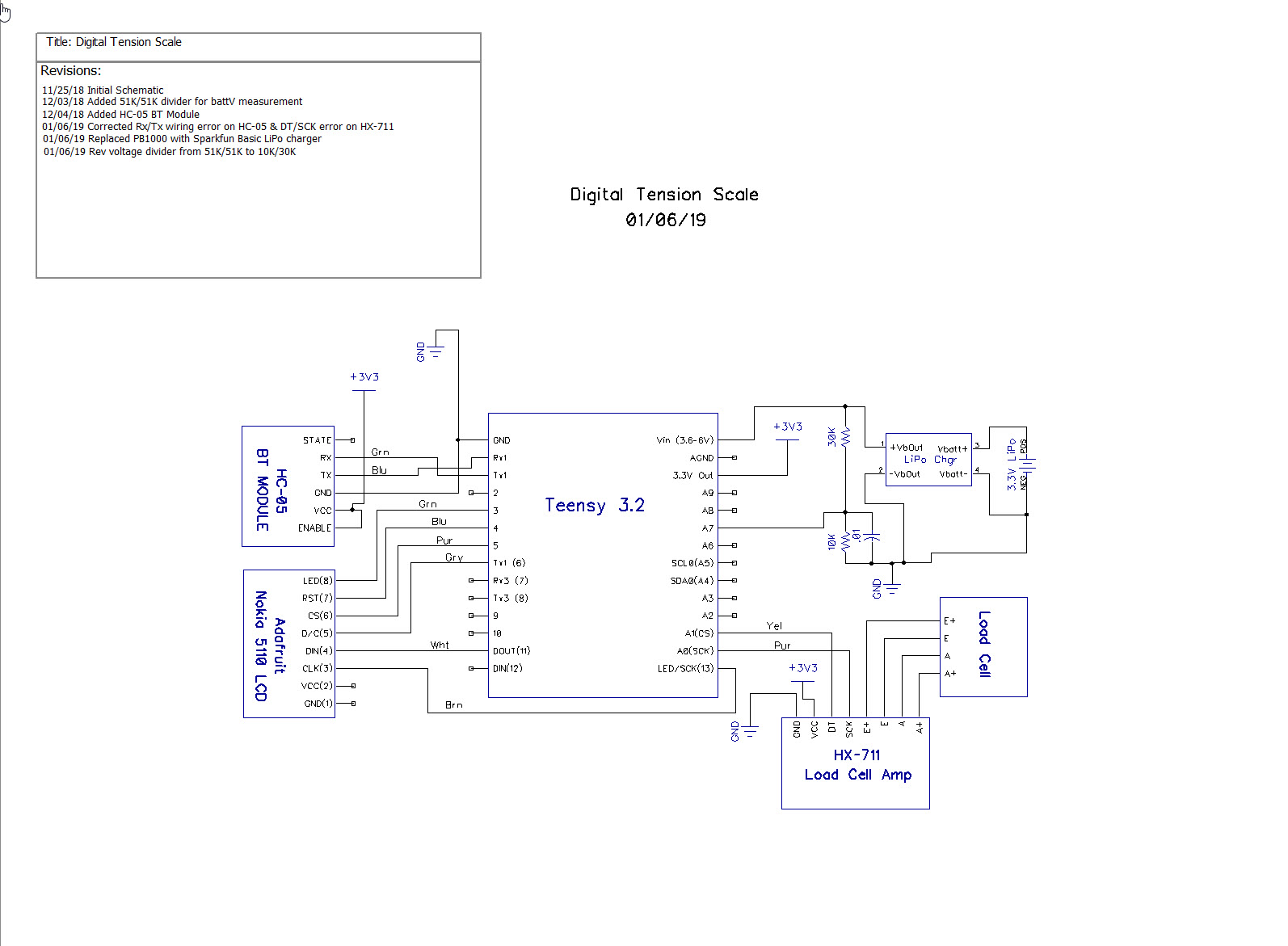
Schematic:
Future Work:
- Do some more work to reduce power consumption to extend the battery life. I got the ‘Snooze’ feature to work on the Teensy, but that only reduces the Teensy’s power consumption; it does nothing directly to reduce the power consumption of the other components. I tried using a MOSFET to turn the HC-05 BT module on & off, and found this to be impractical, as then the module loses its connection to the remote data collection device. I have also tried removing power from the LCD module, but that also turned out to be problematic.
Stay tuned,
Frank