Posted 25 December 2018
In my copious free time I have been refining the design for a low power battery operated tensionometer. In my last post on the subject, I had described the components I had planned to use, and in the ensuing weeks I have been working on implementing this design. There are several challenges in this project:
Bluetooth Link:
There are a huge number of Bluetooth products out there in the Maker-verse, with varying degrees of Arduino support, and widely varying performance characteristics. To add to the confusion, there is ‘regular’ Bluetooth and the more recent ‘BLE’ (Bluetooth Low Energy) which are completely incompatible with each other. As I now understand it, BLE is synonymous with Bluetooth 4.0+ (the iPhone 4S was the first smartphone to implement the new standard). However, the most common product in use in the Arduino world seems to be the venerable HC-05 ‘regular’ Bluetooth module, available from your local grocery store (well, not quite, but from almost everywhere else!) for not much more than a few pennies
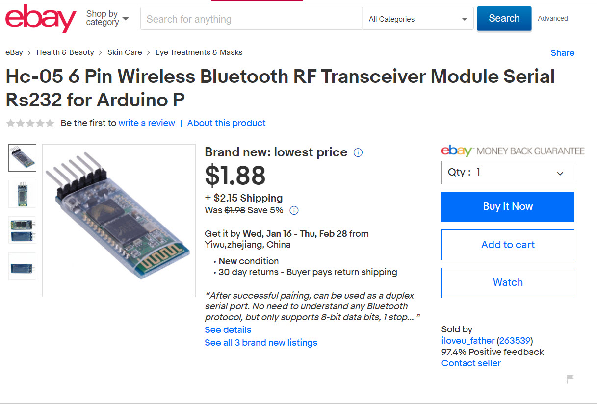
I had no previous experience with BT modules, so this part of the project took some time, and was the last major part to be accomplished. After receiving my HC-05 modules from China, I used this tutorial to get started. The real challenge for this part of the project wasn’t getting the HC-05 hooked up to the microcontroller – it was sorting through all the layers of BT-related settings on my Win 10 laptop to pair with the HC-05 device and determine which serial port did what.
- In Windows 10, I used the ‘Bluetooth and other devices settings’ panel (Settings -> Devices -> Bluetooth and other devices) to find and pair to the HC-05. The device shows up as ‘HC-05’ and the default pairing password is “1234”.
- When the HC-05 is paired it automatically sets up at least two serial ports that show up in device manager as ‘Standard Serial over Bluetooth’ ports, as shown below. However, only one of these ports is actually usable for two-way communication, and it isn’t clear to me why, or how to tell which is which; I had to experiment with each available ‘SSoB’ port to figure out which to use (so far, it seems like the highest-numbered port is the proper one).
- After the HC-05 is paired and the com ports are set up, then any serial terminal app (I used RealTerm) can be used to communicate between the PC and the microcontroller via the HC-05.
- On the microcontroller (I used a Teensy 3.2 with multiple hardware serial ports), I wired the HC-05 to Serial1 leaving Serial (Serial0) available for normal communication between the Teensy and my Visual Studio 2017 Community Edition/Visual Micro add-on for Arduino development platform.
Physical Layout:
The original idea behind this project was to create a self-contained battery-operated digital weight scale that could display weight values on a local display, but could also stream the data live to a remote recording station like a laptop or smartphone. The ‘self-contained’ part requires that all the electronics be mounted on the S-shaped load cell assembly itself, and to that end I designed a housing that connects to the two bolts that hold the arms of the load cell. The idea is that all the electronics save the LCD display and the battery will be mounted to the underside of the box lid so that servicing would be easier. Also, by mounting everything to the lid, I can make cutouts for the charger and Teensy USB connectors for easy charging and reprogramming. After several iterations in TinkerCad, I came up with the following design
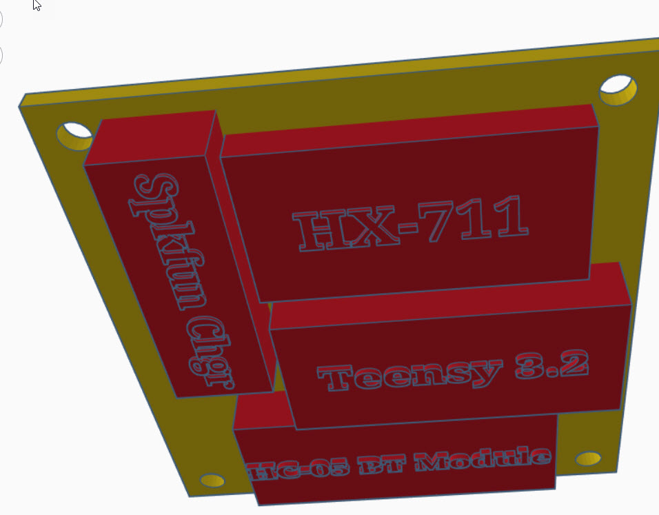
Looking up at the underside of the box lid, showing all modules except the battery and the LCD display
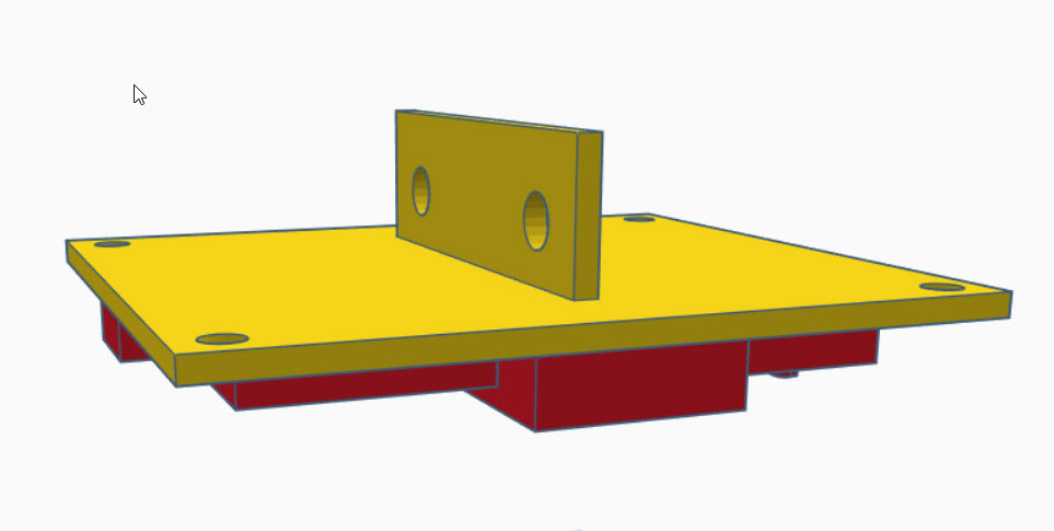
Showing the top of the lid with the mounting bracket for the load cell
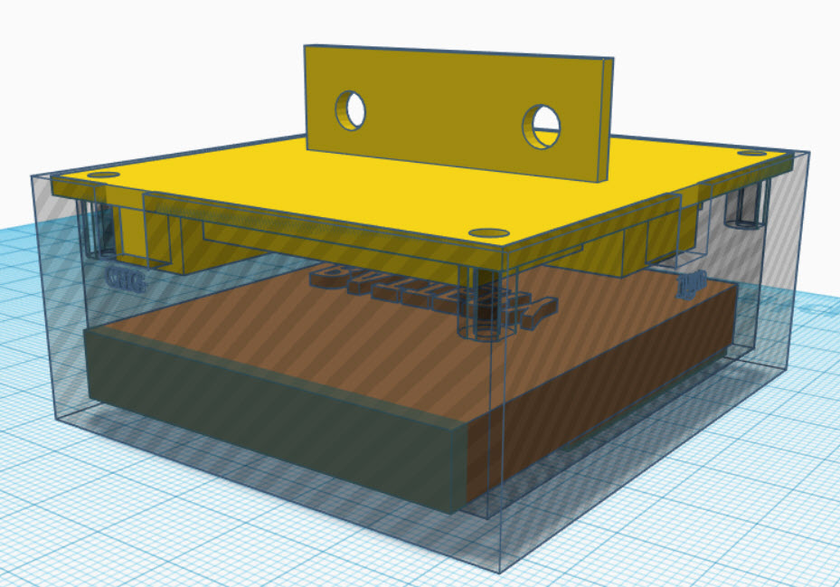
Isometric view with transparent box walls. The LCD display module is under the battery. Note the cutouts for the charging and programming USB-C connections
Module Integration:
I had previously tested each module individually, but hadn’t had all of them working at the same time. I had tested the HC-05 with an Arduino Mega, and I had tested the load cell with both a Sparkfun Pro Micro and with a Teensy 3.2, and I had tested the Nokia LCD display with a Teensy 3.2, but I hadn’t put everything together. So I wired everything up on my half-size ASP plugboard and got it all working together with a simple program (included below) that exercised the LCD Display, the load cell, the BT module, and the battery charger, as shown in the following photos
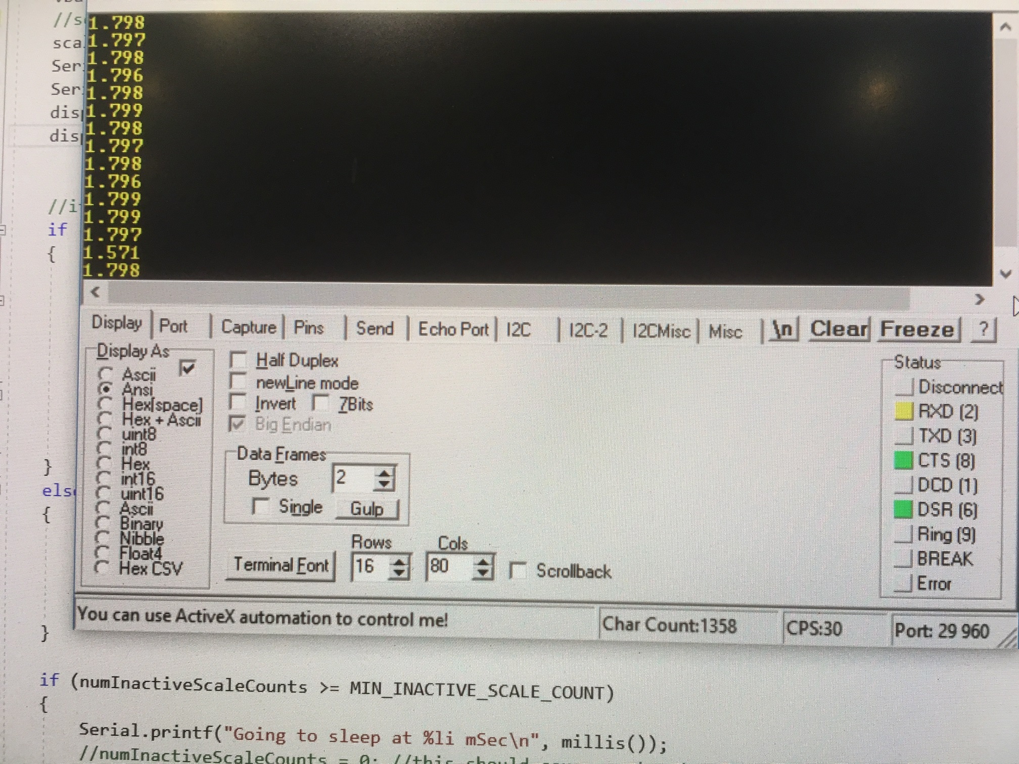
RealTerm Serial Terminal Program showing load cell readouts collected wirelessly via the Bluetooth HC-05 modules
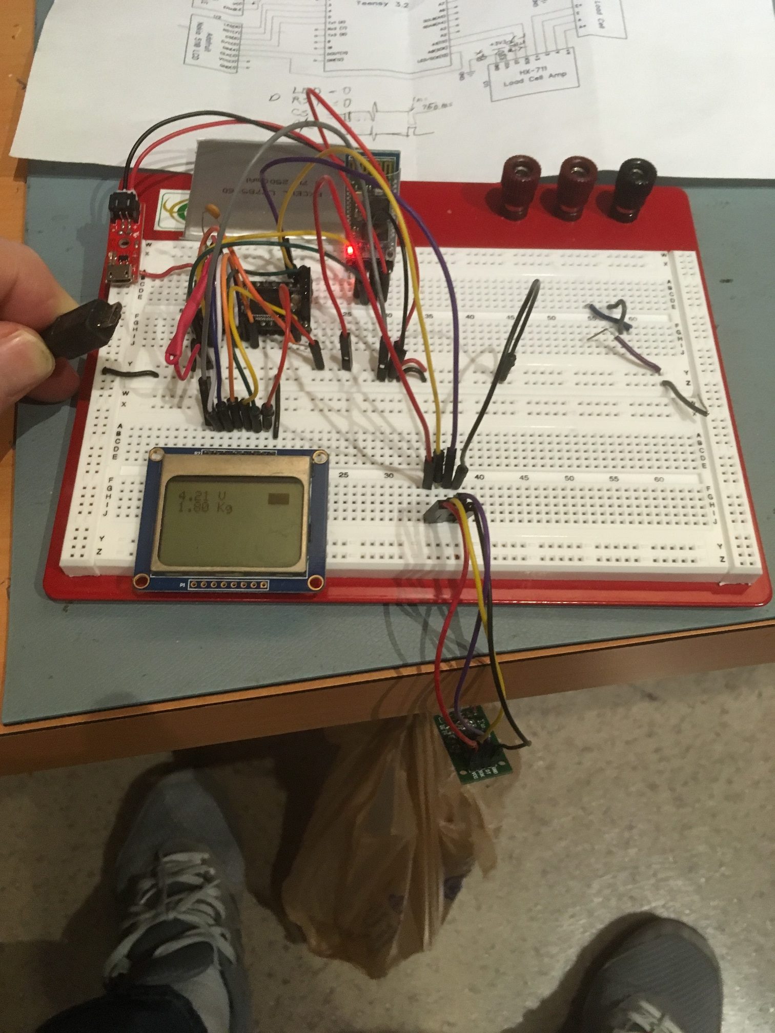
HC-05 Bluetooth, HX-711 Load Cell Amp, Sparkfun Charger, and Teensy Microcontroller modules integrated together. Note disconnected USB cable showing that the circuit is running on battery power. The scale is currently measuring 1.8 liters of water in the suspended plastic bag (note the ‘1.8 Kg’ reading on the LCD display)
Software:
The software used for the above integration tests is a reasonably complete sketch for day-to-day use of the digital weight scale. It displays the measured weight on the LCD display, and also sends it to the USB serial port for display on a directly connected PC, and to the HC-05 Bluetooth module for display/capture via a BT-connected laptop or smartphone. This program is shown below:
|
1 2 3 4 5 6 7 8 9 10 11 12 13 14 15 16 17 18 19 20 21 22 23 24 25 26 27 28 29 30 31 32 33 34 35 36 37 38 39 40 41 42 43 44 45 46 47 48 49 50 51 52 53 54 55 56 57 58 59 60 61 62 63 64 65 66 67 68 69 70 71 72 73 74 75 76 77 78 79 80 81 82 83 84 85 86 87 88 89 90 91 92 93 94 95 96 97 98 99 100 101 102 103 104 105 106 107 108 109 110 111 112 113 114 115 116 117 118 119 120 121 122 123 124 125 126 127 128 129 130 131 132 133 134 135 136 137 138 139 140 141 142 143 144 145 146 147 148 149 150 151 152 153 154 155 156 157 158 159 160 161 162 163 164 165 166 167 168 169 170 171 172 173 174 175 176 177 178 179 180 181 182 183 184 185 186 187 188 189 190 191 192 193 194 195 196 197 198 199 200 201 202 203 204 205 206 207 208 209 210 211 212 213 214 215 216 217 218 219 220 221 222 223 224 225 226 227 228 229 230 231 232 233 234 |
/* Name: TeensyLowPowerDigitalScale.ino Created: 12/2/2018 9:43:43 PM Author: FRANKWIN10\Frank */ #include <SPI.h> #include <Adafruit_GFX.h> #include <Adafruit_PCD8544.h> #pragma region LOW_POWER_SUPP //12/03/18 added for low power mode #include <Snooze.h> // Load just the 'timer' wake-up driver SnoozeTimer timer; SnoozeUSBSerial usb; SnoozeBlock config_teensy32(usb, timer); const int SLEEP_TIME_MSEC = 5000; //const float INACTIVE_SCALE_THRESHOLD_KG = 1.f; const float INACTIVE_SCALE_THRESHOLD_KG = -10.f; //const int MIN_INACTIVE_SCALE_COUNT = 100; const int MIN_INACTIVE_SCALE_COUNT = 20; int numInactiveScaleCounts = 0; #pragma endregion Low Power Support #pragma region LOAD_CELL #include "HX711.h" //You must have this library in your arduino library folder #include <EEPROM.h> #include<EEPROMAnything.h> //so I can read the last calibration value from EEPROM #define DOUT A1 #define CLK A0 HX711 scale(DOUT, CLK); //Change this calibration factor as per your load cell once it is found. You many need to vary it in thousands long calibration_factor = -96650; //-106600 worked for my 40Kg max scale setup long tare_offset = 0; const int LED_PIN = 13; const int CAL_FACTOR_EEPROM_ADDR = 0; const int TARE_OFFSET_EEPROM_ADDR = CAL_FACTOR_EEPROM_ADDR + sizeof(calibration_factor); float scaleKg = 0; float vBatt = 0; #pragma endregion Load Cell Support #pragma region LCD_DISPLAY // Hardware SPI (faster, but must use certain hardware pins): // Note with hardware SPI MISO and SS pins aren't used but will still be read // and written to during SPI transfer. Be careful sharing these pins! // SCK is LCD serial clock (SCLK) - this is pin 13 on Arduino Uno // MOSI is LCD DIN - this is pin 11 on an Arduino Uno // pin 6 - Data/Command select (D/C) // pin 5 - LCD chip select (CS) // pin 4 - LCD reset (RST) const int LCD_DC_PIN = 6; const int LCD_CS_PIN = 5; const int LCD_RST_PIN = 4; const int SPI_DOUT_PIN = 11; const int SPI_SCK_PIN = A0; //Adafruit_PCD8544 display = Adafruit_PCD8544(6, 5, 4);//11/25/18 Adafruit_PCD8544 display = Adafruit_PCD8544(LCD_DC_PIN, LCD_CS_PIN, LCD_RST_PIN);//12/16/18 chg to identifiers #pragma endregion Noki LCD Display #pragma region BATT_FUEL_GUAGE const int BATT_SYMBOL_X = 68; const int BATT_SYMBOL_Y = 1; const int BATT_SYMBOL_H = 8; const int BATT_SYMBOL_W = 16; const int DEFAULT_CHAR_HEIGHT = 8; const int DEFAULT_CHAR_WIDTH = 5; const int DEFAULT_CHAR_SIZE = 2; //added 12/03/18 for battV measurements //12/06/18 changed to internal 1.2V reference and 30K:10K divider const int DEAD_BATT_COUNTS = 642; const int FULL_BATT_COUNTS = 887; const float FULL_BATT_VOLTS = 4.2; const float DEAD_BATT_VOLTS = 3.0; const float VOLTS_PER_COUNT = (FULL_BATT_VOLTS - DEAD_BATT_VOLTS) / (FULL_BATT_COUNTS - DEAD_BATT_COUNTS); #pragma endregion Battery Fuel Guage void setup() { Serial.begin(115200); delay(1000); //need this to get serial printout Serial.println("Welcome to the Teensy Low Power Digital Scale Program"); Serial1.begin(9600); Serial1.println("Welcome via Bluetooth!"); /******************************************************** Set Low Power Timer wake up in milliseconds. ********************************************************/ timer.setTimer(SLEEP_TIME_MSEC);// milliseconds //12/04/18 added code to set analog reference to internal 1.2V source analogReference(INTERNAL1V1); //initialize load cell and retrieve cal/tar values from EEPROM EEPROM_readAnything(CAL_FACTOR_EEPROM_ADDR, calibration_factor); //read current cal scale from EEPROM Serial.printf("The current stored scale calibration factor is %li\n", calibration_factor); scale.set_scale(calibration_factor); EEPROM_readAnything(TARE_OFFSET_EEPROM_ADDR, tare_offset); //read current tare offset from EEPROM Serial.printf("The current stored tare offset factor is %li\n", tare_offset); scale.set_offset(tare_offset); //initialize LCD display display.begin(); display.setContrast(60); //pretty dark display.setTextSize(1); display.setTextColor(BLACK); display.setCursor(0, 0); display.display(); //first time - shows the Adafruit logo delay(1000); //show Adafruit logo for 1 sec display.clearDisplay(); // clears the screen and buffer display.display(); //first time - shows the Adafruit logo ////initial battery and scale reading //vBatt = UpdateBatteryDisplay(); //scaleKg = UpdateScaleDisplay(); //display.display(); } void loop() { //12/06/18 now using 30K/10K voltage divider on A7 and 1.2V ref. display.clearDisplay(); //clear memory bitmap display.setCursor(0, 0); vBatt = UpdateBatteryDisplay(); //scaleKg = UpdateScaleDisplay(); scaleKg = scale.get_units(3); Serial1.printf("%5.3f\n\r", scaleKg); //to BT module Serial.printf("%5.3f\n", scaleKg); //to serial console display.print(scaleKg); display.println(" Kg");//to LCD display display.display(); //if the scale has been quiet for a while, go to sleep if (scaleKg <= INACTIVE_SCALE_THRESHOLD_KG) { numInactiveScaleCounts++; if (numInactiveScaleCounts >= MIN_INACTIVE_SCALE_COUNT) { numInactiveScaleCounts = MIN_INACTIVE_SCALE_COUNT; } //numInactiveScaleCounts = (numInactiveScaleCounts >= MIN_INACTIVE_SCALE_COUNT) ? // MIN_INACTIVE_SCALE_COUNT : numInactiveScaleCounts++; //display.display(); } else { numInactiveScaleCounts = 0; //one active measurment wakes everything up //vBatt = UpdateBatteryDisplay(); //scaleKg = UpdateScaleDisplay(); //display.display(); } if (numInactiveScaleCounts >= MIN_INACTIVE_SCALE_COUNT) { Serial.printf("Going to sleep at %li mSec\n", millis()); //numInactiveScaleCounts = 0; //this should cause system to stay awake for a second or so display.clearDisplay(); display.display(); Snooze.sleep(config_teensy32); //sleep } delay(100); } float UpdateScaleDisplay() { float kG = scale.get_units(3); //float kG = (float)random(0,40); display.print(kG); display.println(" Kg"); return kG; } float UpdateBatteryDisplay() { int batt_counts = analogRead(A9); float batt_volts = DEAD_BATT_VOLTS + (batt_counts - DEAD_BATT_COUNTS) * VOLTS_PER_COUNT; display.print(batt_volts); display.println(" V"); UpdateBatterySymbol(batt_volts); return batt_volts; } void UpdateBatterySymbol(float vbatt) { //Purpose: Update the battery symbol to show current charge state //Inputs: // vbatt = current battery voltage // FULL_BATT_VOLTS = fully charged battery voltage // DEAD_BATT_VOLTS = fully discharged battery voltage // BATT_SYMBOL_X/Y/H/W = battery symbol loc/dims //Outputs: Updated battery symbol //Plan: // Step1: draw open rect for battery symbol outline // Step2: draw filled rect indicating charge state // Step3: If vbatt <= DEAD_BATT_VOLTS, draw 'X' over symbol //Step1: draw open rect for battery symbol outline display.drawRect(BATT_SYMBOL_X, BATT_SYMBOL_Y, BATT_SYMBOL_W, BATT_SYMBOL_H, 1); //Step2: draw filled rect indicating charge state float Vrange = FULL_BATT_VOLTS - DEAD_BATT_VOLTS; int fillWidth = (int)(BATT_SYMBOL_W * ((vbatt - DEAD_BATT_VOLTS) / Vrange) + 0.5f); //Serial.printf("vbat, fillW = %4.2f,%d\n", vbatt, fillWidth); display.fillRect(BATT_SYMBOL_X, BATT_SYMBOL_Y, fillWidth, BATT_SYMBOL_H, 1); //Step3: If vbatt <= DEAD_BATT_VOLTS, draw 'X' over symbol if (vbatt <= DEAD_BATT_VOLTS) { //try drawing lines from corner to corner int ulX = BATT_SYMBOL_X; int ulY = BATT_SYMBOL_Y; int urX = BATT_SYMBOL_X + BATT_SYMBOL_W; int urY = ulY; int lrX = urX; int lrY = urY + BATT_SYMBOL_H; int llX = ulX; int llY = lrY; display.drawLine(ulX, ulY, lrX, lrY, 1); display.drawLine(llX, llY, urX, urY, 1); } } |
However, this program depends on the proper calibration of the load cell, which I have been doing with a separate sketch (also included below):
|
1 2 3 4 5 6 7 8 9 10 11 12 13 14 15 16 17 18 19 20 21 22 23 24 25 26 27 28 29 30 31 32 33 34 35 36 37 38 39 40 41 42 43 44 45 46 47 48 49 50 51 52 53 54 55 56 57 58 59 60 61 62 63 64 65 66 67 68 69 70 71 72 73 74 75 76 77 78 79 80 81 82 83 84 85 86 87 88 89 90 91 92 93 94 95 96 97 98 99 100 101 102 103 104 105 106 107 108 109 110 111 112 113 114 115 116 117 118 119 120 121 122 123 124 125 126 127 128 129 130 131 132 133 134 135 136 137 138 139 140 141 142 143 144 145 146 147 148 149 150 151 152 153 154 155 156 157 158 159 160 161 162 163 164 165 166 167 168 169 170 171 172 173 174 175 176 177 178 179 180 181 182 183 184 185 186 187 188 189 190 191 192 193 194 195 196 197 198 199 200 201 202 203 204 205 206 207 208 209 210 211 212 213 214 215 216 217 218 219 220 221 222 223 224 225 226 |
/* Name: TeensyDigitalScaleCalibration.ino Created: 12/11/2018 8:47:58 PM Author: FRANKWIN10\Frank */ /* Name: DigitalScaleAutoCal.ino Created: 11/15/2018 4:49:12 PM Author: FRANKWIN10\Frank This program is a modification of the November 2016 circuits4you.com program for interfacing with the HX711 Module coupled with a typical load cell. It's purpose is to automatically calibrate the combination to accurately display weight in Kg. The process is as follows: Step1: User opts to calibrate by entering 'Y' at the prompt. Entering any other key (or just letting the question time out) will skip the calibration process Step2: User establishes 'tare' weight physical configuration with any non-measured weight attached (in my case, the bucket used to hold measured amounts of water used for weight calibration), and then presses 'T' to zero out the 'tare weight' Step3: The user establishes a calibration weight condition (in my case, 1.8 liters of water) and enters the weight value (in Kg). The program then calculates the scale factor needed to calibrate the scale for the entered weight and then automatically drops into measurement mode Step5: The user enters 'q' to quit measurements. */ /* * circuits4you.com * 2016 November 25 * Load Cell HX711 Module Interface with Arduino to measure weight in Kgs Arduino pin 2 -> HX711 CLK 3 -> DOUT 5V -> VCC GND -> GND Most any pin on the Arduino Uno will be compatible with DOUT/CLK. The HX711 board can be powered from 2.7V to 5V so the Arduino 5V power should be fine. */ #include "HX711.h" //You must have this library in your arduino library folder #include <EEPROM.h> #include<EEPROMAnything.h> //so I can store the last calibration value in EEPROM #include <elapsedMillis.h> elapsedMillis sinceLastWaitMsg; const int WAITINGMSGINTERVALMSEC = 1000; //1-sec intervals const int MAX_WAITING_INTERVALS = 10; //how long to wait before starting measurement int numWaitIntervals = 0; char inbuf[20]; //buffer for user input #define DOUT A1 #define CLK A0 HX711 scale(DOUT, CLK); //Change this calibration factor as per your load cell once it is found. You many need to vary it in thousands long calibration_factor = -96650; //-106600 worked for my 40Kg max scale setup long tare_offset = 0; bool bDoneMeasuring = false; const int LED_PIN = 13; const char* waitstr = "Waiting...Measurements will start in "; const int CAL_FACTOR_EEPROM_ADDR = 0; const int TARE_OFFSET_EEPROM_ADDR = CAL_FACTOR_EEPROM_ADDR + sizeof(calibration_factor); void setup() { delay(2000); //required to wait for Pro Micro to switch from programming to output serial port assignments Serial.begin(115200); pinMode(LED_BUILTIN, OUTPUT); memset(inbuf, 0, sizeof(inbuf)); Serial.printf("Digital Scale Program\n"); Serial.printf("Program to automatically calibrate HX711/Load Cell to measure weight in Kg\n"); EEPROM_readAnything(CAL_FACTOR_EEPROM_ADDR, calibration_factor); //read current cal scale from EEPROM Serial.printf("The current stored scale calibration factor is %li\n", calibration_factor); if (isnan((float)calibration_factor)) { Serial.printf("invalid cal factor: Setting to -96650\n"); calibration_factor = -96650; } scale.set_scale(calibration_factor); EEPROM_readAnything(TARE_OFFSET_EEPROM_ADDR, tare_offset); //read current tare offset from EEPROM Serial.printf("The current stored tare offset factor is %li\n", tare_offset); if (isnan((float)tare_offset)) { Serial.printf("invalid cal factor: Setting to zero\n"); tare_offset = 0; } scale.set_offset(tare_offset); Serial.printf("Enter 'Y' to start the calibration, any other key to skip\n"); Serial.printf("Calibrate (Y/N) (Y)?\n"); if (GetUserInputStr(inbuf, 5)) //returns true if strlen(inbuf) > 0 { Serial.printf("\nReceived "); Serial.print(inbuf); Serial.println(" from user"); if (strncasecmp("Y", inbuf, 1) == 0) //compare only 1st chars, as user input may have CR/LF appended { //calibrate with known weights Serial.println("HX711 Calibration"); Serial.println("Remove all non-fixture weight from scale, and press 't' to zero the scale"); Serial.println("Or any other character to skip this step"); memset(inbuf, 0, sizeof(inbuf)); if (GetUserInputStr(inbuf, 10)) //returns true if strlen(inbuf) > 0 { Serial.printf("\nReceived "); Serial.print(inbuf); Serial.println(" from user"); if (strncasecmp("T", inbuf, 1) == 0) //compare only 1st chars, as user input may have CR/LF appended { tare_offset = scale.read_average(); //Get a baseline reading Serial.printf("Applying offset %li as tare adjustment\n", tare_offset); scale.set_offset(tare_offset); //this value will be subtracted from all future measurements Serial.printf("Writing offset %li to EEPROM address %d\n", tare_offset, TARE_OFFSET_EEPROM_ADDR); EEPROM_writeAnything(TARE_OFFSET_EEPROM_ADDR, tare_offset); EEPROM_readAnything(TARE_OFFSET_EEPROM_ADDR, tare_offset); Serial.printf("Read offset %li from EEPROM address %d\n", tare_offset, TARE_OFFSET_EEPROM_ADDR); } } Serial.println("Apply a known weight (the higher the better) and enter its value in Kg"); Serial.println("Enter 0 to skip this step"); memset(inbuf, 0, sizeof(inbuf)); if (GetUserInputStr(inbuf, 30)) //returns true if strlen(inbuf) > 0 { Serial.printf("\nReceived "); Serial.print(inbuf); Serial.println(" from user"); //calculate scale factor resulting in user-input wt //wt(Kg) = (read_avg - OFFSET)/Scale //Scale = (read_avg - OFFSET)/wt(Kg) double wtKg = atof(inbuf); Serial.printf("User weight input was %4.2f\n", wtKg); long read_avg = scale.read_average(); long offset = scale.get_offset(); calibration_factor = (double)(read_avg - offset) / wtKg; scale.set_scale(calibration_factor); //Adjust to this calibration factor Serial.printf("User weight input was %4.2f, read_avg = %li, offset = %li, cal = ", wtKg, read_avg, offset); Serial.println(calibration_factor); //PrintEx won't print the cal factor value EEPROM_writeAnything(CAL_FACTOR_EEPROM_ADDR, calibration_factor); Serial.print("Wrote cal factor "); Serial.print(calibration_factor); //Serial.printf doesn't work for cal factor Serial.printf(" to EEPROM address %d\n", CAL_FACTOR_EEPROM_ADDR); EEPROM_readAnything(CAL_FACTOR_EEPROM_ADDR, calibration_factor); Serial.print("Read cal factor "); Serial.print(calibration_factor); //Serial.printf doesn't work for cal factor Serial.printf(" from EEPROM address %d\n", CAL_FACTOR_EEPROM_ADDR); } } } Serial.printf("\n\nCalibration Complete... Starting Measurements\n\n"); Serial.printf("\nTo quit measuring, enter 'Q'\n"); Serial.printf("Time(mSec)\tWt(Kg)\n"); bDoneMeasuring = false; while (!bDoneMeasuring) { Serial.printf("%lu\t%3.2f\n", millis(), scale.get_units(3)); delay(250); if (Serial.available()) { char temp = Serial.read(); Serial.printf("got %c\n", temp); if (temp == 'q') { bDoneMeasuring = true; //all done } } } Serial.printf("Measurements Completed - Have a nice day!\n"); } void loop() { } bool GetUserInputStr(char* inbuf, int numWaitIntervals) { //Purpose: Get user input //Inputs: // inbuf = pointer to char[10] array to receive user input //Outputs: // inbuf = String object containing user input. If inbuf.length() == 0, then the routine timed out // returns True if user input was received, False if the routine timed out //Plan: // Wait for user input or timeout whichever occurs first int intervalCount = 0; while (strlen(inbuf) <= 0 && intervalCount < numWaitIntervals) { Serial.readBytesUntil('\n', inbuf, 10); if (sinceLastWaitMsg >= WAITINGMSGINTERVALMSEC) { sinceLastWaitMsg -= WAITINGMSGINTERVALMSEC; intervalCount++; Serial.printf("%s %d\n", waitstr, numWaitIntervals - intervalCount); } delay(250); } return (strlen(inbuf) > 0); } |
What I need to do now is to combine these two programs into a single sketch with ‘operating’ and ‘calibration’ modes. My calibration program already does this to some degree, as it waits 5 seconds on startup for the operator to send the ‘y’ key via the direct-connect serial port. If the ‘y’ character is detected within this window, then the program starts the calibration sequence; otherwise it starts taking measurements as normal. This behavior needs to be expanded somewhat in that it should accept a calibration command either through the direct-connect serial port (Serial) or via the BT port (Serial1).
Low Power Operation:
I have already done some experimentation on low-power operation of the Teensy 3.2, using Colin Duffy’s fine ‘Snooze’ library, and have determined that I can easily drop the Teensy’s operating current from around 20-30 mA to about 1-2 mA by putting it to sleep during periods of load cell inactivity. Assuming I get the full 2500 mA hours out of the battery, then I can expect something like 1000 hours or about 40 days between recharges. However, more work needs to be done to get the low power mode fully operational.
Stay Tuned!
Frank