Posted 06 June 2018
About a month ago in early May I started another try at adding time, memory, and heading super-powers to Wall-E2’s repertoire. In this post, I described the effort to add a FRAM board, an RTC board, and a 9DOF MPU9050 IMU board to Wall-E2’s already-existing I2C bus, and in this post I described fabricating a permanent ‘tri-sensor board’ for installation on Wall-E2’s second deck.
After installing the tri-sensor board on the second deck, I did some tests to confirm Wall-E2’s new found ability to make accurate turns, and instead of confirming success, I witnessed complete failure – Wall-E2 was even worse at making turns now than in the past when he was just doing timed turns – WTF!!
Backing up and doing some more tests, it quickly became apparent that the MPU9050 IMU worked fine until Wall-E2’s wheel motors started running, but went completely ga-ga after that. I tried some quick tests to try and isolate the problem, but didn’t get anywhere. So, I did what I always do when faced with an apparently intractable problem – I ran away ;-). OK, I didn’t really run away, but I decided to put the whole thing on the back burner for a while and let my subconscious work on it for a while (I have discovered over and over again that my subconscious is a lot smarter than I am). In the meantime I had some other stuff to do, like going to a duplicate bridge tournament and going to a grand-daughter’s HS graduation.
After doing some web research, I began to suspect that the problem might be associated with the complexity associated with the Sparkfun 9DOF MPU9050 chip and the associated yaw/pitch/roll computation software, so I decided to see if there were other IMU solutions out there. I ran across the DFRobots MPU-6050 6DOF IMU breakout board.
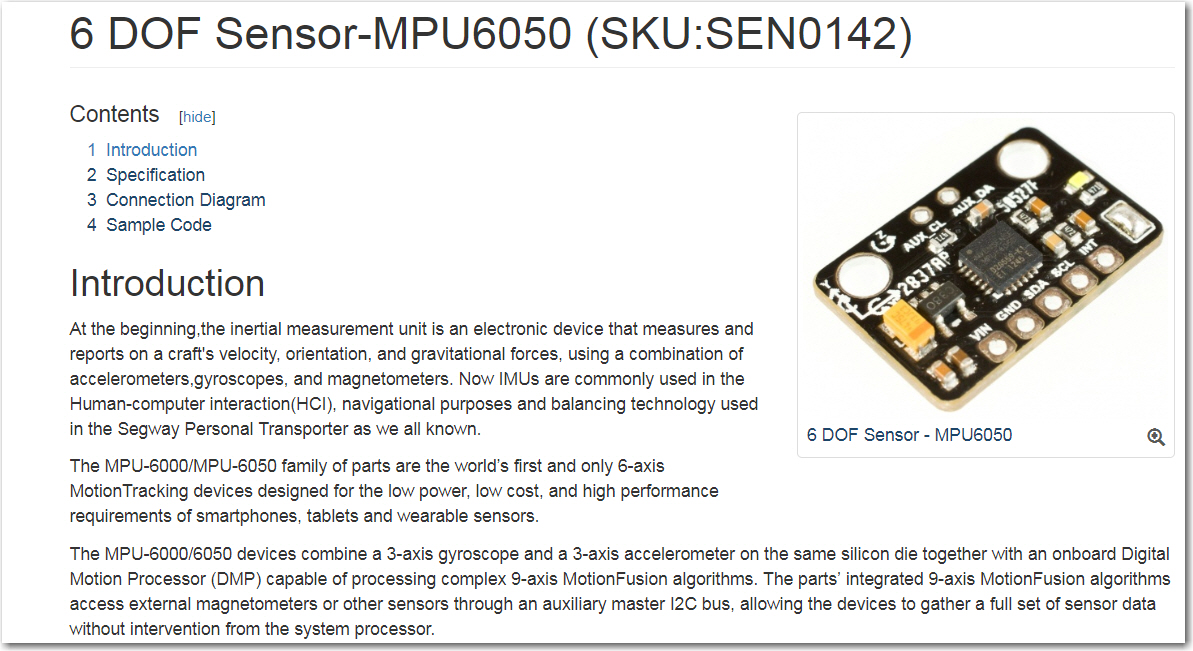
Since I wasn’t planning to use this for anything but yaw (z-axis rotation) information, the 6DOF limitation wasn’t a problem, and the integrated Digital Motion Processorâ„¢ (DMP) should simplify the control software. In addition, the IMU6050 board is 5V compatible, so I can eliminate the level-shifting hardware required for the Sparkfun 9250 unit. So, I ordered a couple of units and started playing with them. Using the supplied libraries from DFRobots and their little example program, I was able to get the unit up and running fairly quickly. To test the ability to report yaw excursions, I modified the test program to report only yaw, and manually turned the sensor around its Z-axis. As shown below, the yaw progressed smoothly.
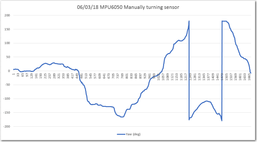
Manually turned sensor while recording yaw
Next, I mounted just the IMU6050 board on the robot’s 2nd deck, as shown below, and ran some tests with and without the motor running.
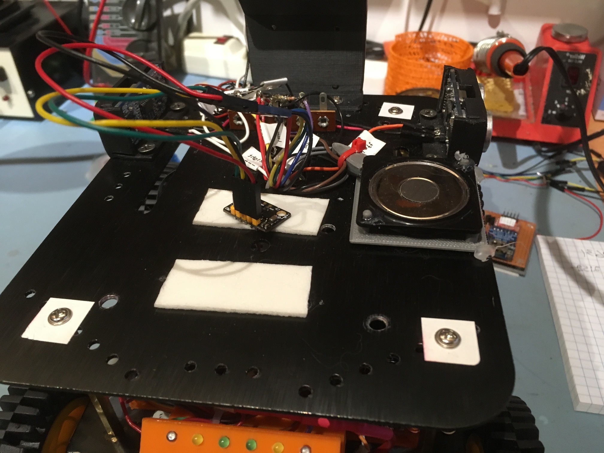
MPU6050 mounted on robot with double-sided tape
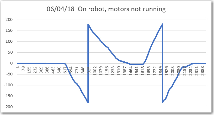
Sensor mounted on robot with double-sided tape, no motors running
As shown above, with the sensor mounted on the 2nd deck and with motors not running, I got a smooth response from the yaw sensor as the robot was manually rotated. However, when I tried the same trick with the motors running, I got the following plot:
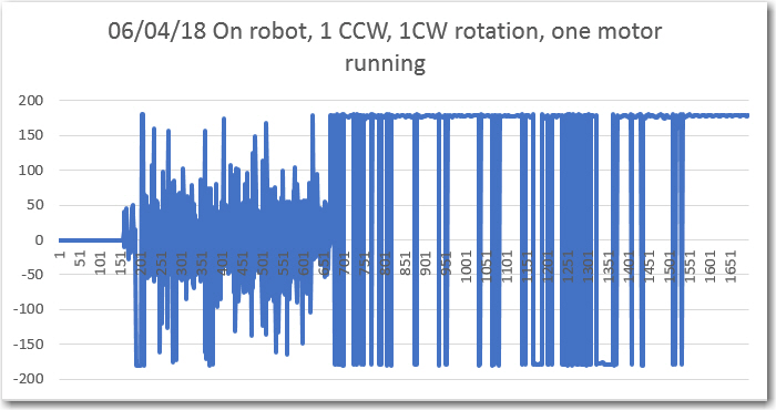
Sensor mounted on robot with double-sided tape, left rear motor running
Then I mounted the sensor on an ‘air pillow’ (one section of a piece of air-filled packing material) and tried again, once again getting a smooth plot, even with one motor running.
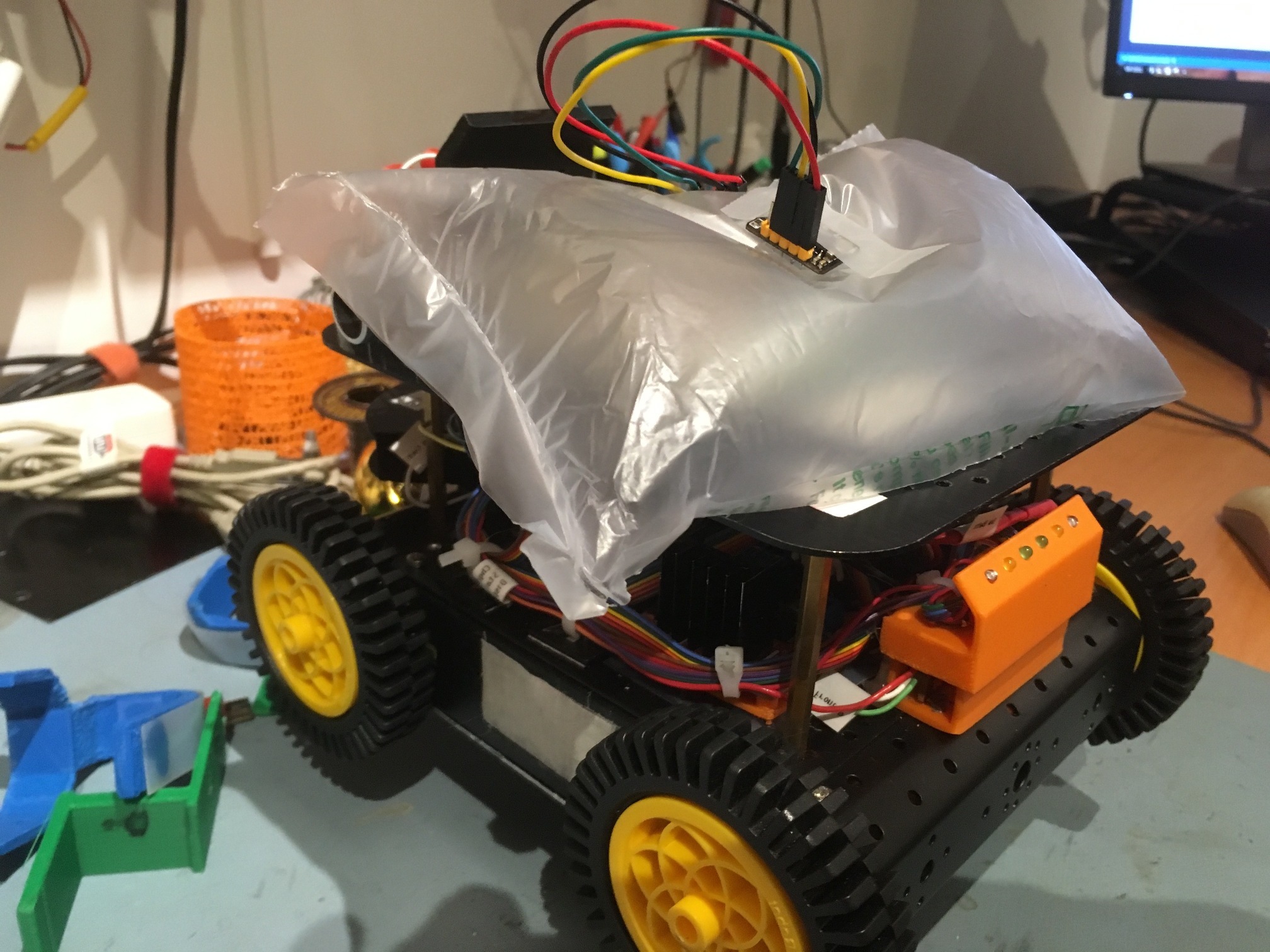
MPU 6050 mounted on robot with an ‘air pillow’ (piece of some air-filled packing material)
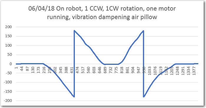
6050 sensor mounted on air pillow, left rear wheel motor running