Posted 06 May 2018
For the last two months I have been working on adding some secondary, but still important capabilities to Wall-E2, my wall-following autonomous robot. As I noted back in April, Wall-E2 still can’t tell which way he is heading, which (among other problems) means he can’t make accurate turns. In addition, Wall-E2 can’t tell how long (or even if) he has been turned off, making it impossible to tell how long it has been since he last was charged.
In the intervening months, I have been able to obtain and test individual modules to address the above issues; the Sparkfun MPU9250 9DOF IMU breakout board to obtain heading information, and the combination of an Adafruit MB85RC256V FRAM breakout board and an Adafruit DS3221 RTC breakout board to capture the date/time of any power interruptions.
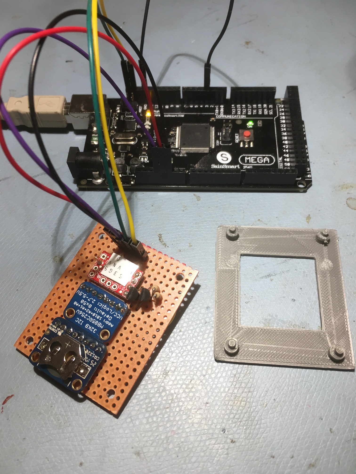
Since all three of the above breakout boards are I2C-capable, it should be feasible to run all three from a single I2C bus on Wall-E2’s main controller – an Arduino Mega 2560. Unfortunately, the Sparkfun MPU9250 module isn’t 5V tolerant, so integrating all three isn’t as simple as just daisy-chaining them all together. Back to Google for some more research, where I eventually uncovered Philips Application Note AN97055 by Herman Schutte of The Netherlands dealing with bidirectional level-shifters for just this problem. Turns out that Philips introduced the I2C bus back in 1980, so they may know a thing or two about the issues ;-). In any case, this 1997 paper described a 2-MOSFET bidirectional level-shifter that completely addresses the issue, and seemed to be pretty straightforward to implement. It took me a couple of tries, but I got it working, with the result that I can now run all three modules (RTC, FRAM and IMU) from an Arduino Mega 2560, with the level-shifting MOSFET’s placed between the IMU and the rest of the circuit, as shown in the photo below.
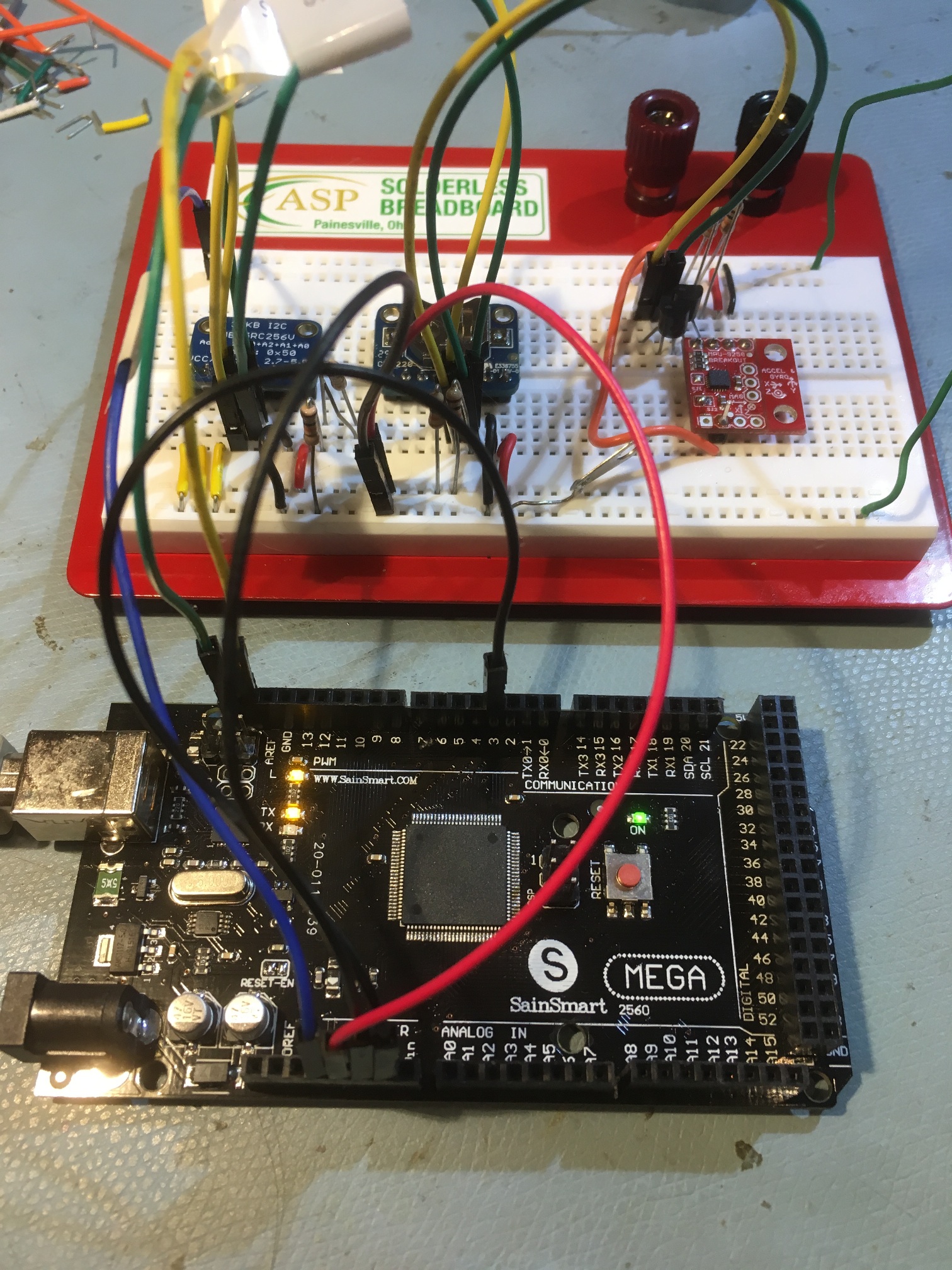
All three sensors operating a the same time, controlled over a single I2C channel.
In the above photo, the modules are (from left to right): Adafruit MB85RC256K FRAM breakout, Adafruit DS3231 RTC breakout, and Sparkfun MPU9250 9DOF IMU breakout. The two 2N7000 level-shifter MOSFETs can be seen at the top left-hand corner of the Sparkfun IMU breakout board.
I put together a small test program, combining pieces from the software used to test the power-down date/time capture idea, and the software used to test the ability to use the Sparkfun IMU to accurately manage rotations. This program doesn’t do much at all, but it does demonstrate that all three modules can be controlled at the same time over a single I2C channel, as shown in the following output.
|
1 2 3 4 5 6 7 8 9 10 11 12 13 14 15 16 17 18 19 20 21 22 23 24 25 26 27 28 29 30 31 32 33 34 35 36 37 38 39 40 41 42 43 44 45 46 47 48 49 50 51 52 53 54 55 56 57 58 59 60 61 62 63 64 65 66 67 68 69 70 71 72 73 74 75 76 77 78 79 80 81 82 83 84 85 86 87 88 89 90 91 92 93 94 95 96 97 98 99 100 101 102 103 104 105 106 107 108 109 110 111 112 113 114 115 116 117 118 119 120 121 122 123 124 125 126 127 128 129 130 131 132 133 134 135 136 137 138 139 140 141 142 143 144 145 146 147 148 149 150 151 152 153 154 155 156 157 158 159 160 161 162 163 164 165 166 167 168 169 170 171 172 173 174 175 176 177 178 179 180 181 182 183 184 185 186 187 188 189 190 191 192 193 194 195 196 197 198 199 200 201 202 203 204 205 206 207 208 209 210 211 212 213 214 215 216 217 218 219 220 221 222 223 224 225 226 227 228 229 230 231 232 233 234 235 236 237 238 239 240 241 242 243 244 245 246 247 248 249 250 251 252 253 254 255 256 257 258 259 260 261 262 263 264 265 266 267 268 269 270 271 272 273 274 275 276 277 278 279 280 281 282 283 284 285 286 287 288 289 290 291 292 293 294 295 296 297 298 299 300 301 302 303 304 305 306 307 308 309 310 311 312 313 314 315 316 317 318 319 320 321 322 323 324 325 326 327 328 329 330 331 332 333 334 335 336 337 338 339 340 341 342 343 344 345 346 347 348 349 350 351 352 353 354 355 356 357 358 359 360 361 362 363 364 365 366 367 368 369 370 371 372 373 374 375 376 377 378 379 380 381 382 383 384 385 386 387 388 389 390 391 392 393 394 395 396 397 398 399 400 401 402 403 404 405 406 407 408 409 410 411 412 413 414 415 416 417 418 419 420 421 422 423 424 425 426 427 428 429 430 431 432 433 434 435 436 437 438 439 440 441 442 443 444 445 446 447 448 449 450 451 452 453 454 455 456 457 458 459 460 461 462 463 464 465 466 467 468 469 470 471 472 473 474 475 476 477 478 479 480 481 482 483 484 485 486 487 488 489 490 491 492 493 494 495 496 497 498 499 500 501 502 503 504 505 506 507 508 509 510 511 512 513 514 515 516 517 518 519 520 521 522 523 524 525 526 527 528 529 530 531 532 533 534 535 536 537 538 539 540 541 542 543 544 545 546 547 548 549 550 551 552 553 554 555 556 557 558 559 560 561 562 563 564 565 |
Opening port Port open Starting program, Scanning I2C addresses... Scanning... I2C device found at address 0x0C ! I2C device found at address 0x50 ! I2C device found at address 0x68 ! I2C device found at address 0x69 ! I2C device found at address 0x7C ! done Initializing 9250 IMU... MPU9250 I AM 71 I should be 71 MPU9250 is online - doing self-test... Starting gyro/accel calibration - keep IMU motionless until finished... gyro/accel calibration complete. Calibration took 381 Msec MPU9250 initialized for active data mode.... Done... Found I2C FRAM Restarted 8 times Displaying contents of first 50 memory locations... 0x0: 0x9 0x00 0x00 0x00 0x00 0x00 0x00 0x00 0x00 0x00 0x00 0x00 0x00 0x00 0x00 0x00 0x00 0x00 0x00 0x00 0x00 0x00 0x00 0x00 0x00 0x00 0x00 0x00 0x00 0x00 0x00 0x00 0x20: 0x00 0x00 0x00 0x00 0x00 0xBE 0x00 0x00 0x00 0x00 0x00 0x00 0x00 0x00 0x00 0x00 0x00 0x00 In Loop()... 2018/5/6 (Sunday) 22:5:23 IMU Hdg = 21.79 2018/5/6 (Sunday) 22:5:23 IMU Hdg = 21.62 2018/5/6 (Sunday) 22:5:23 IMU Hdg = 21.42 2018/5/6 (Sunday) 22:5:23 IMU Hdg = 21.18 2018/5/6 (Sunday) 22:5:24 IMU Hdg = 20.93 2018/5/6 (Sunday) 22:5:24 IMU Hdg = 20.64 2018/5/6 (Sunday) 22:5:24 IMU Hdg = 20.33 2018/5/6 (Sunday) 22:5:24 IMU Hdg = 19.98 2018/5/6 (Sunday) 22:5:24 IMU Hdg = 19.57 2018/5/6 (Sunday) 22:5:25 IMU Hdg = 19.12 0x0: 0x9 0x00 0x00 0x3 0x00 0x00 0x00 0x00 0x00 0x00 0x00 0x00 0x00 0x00 0x00 0x00 0x00 0x00 0x00 0x00 2018/5/6 (Sunday) 22:5:25 IMU Hdg = 18.59 2018/5/6 (Sunday) 22:5:25 IMU Hdg = 18.02 2018/5/6 (Sunday) 22:5:25 IMU Hdg = 17.33 2018/5/6 (Sunday) 22:5:25 IMU Hdg = 16.59 2018/5/6 (Sunday) 22:5:26 IMU Hdg = 15.75 2018/5/6 (Sunday) 22:5:26 IMU Hdg = 14.84 2018/5/6 (Sunday) 22:5:26 IMU Hdg = 13.78 2018/5/6 (Sunday) 22:5:26 IMU Hdg = 12.59 2018/5/6 (Sunday) 22:5:26 IMU Hdg = 11.29 2018/5/6 (Sunday) 22:5:27 IMU Hdg = 9.86 0x0: 0x9 0x00 0x00 0x3 0x4 0x00 0x00 0x00 0x00 0x00 0x00 0x00 0x00 0x00 0x00 0x00 0x00 0x00 0x00 0x00 2018/5/6 (Sunday) 22:5:27 IMU Hdg = 8.32 2018/5/6 (Sunday) 22:5:27 IMU Hdg = 6.70 2018/5/6 (Sunday) 22:5:27 IMU Hdg = 5.00 2018/5/6 (Sunday) 22:5:27 IMU Hdg = 3.32 2018/5/6 (Sunday) 22:5:28 IMU Hdg = 1.71 2018/5/6 (Sunday) 22:5:28 IMU Hdg = 0.33 2018/5/6 (Sunday) 22:5:28 IMU Hdg = -0.70 2018/5/6 (Sunday) 22:5:28 IMU Hdg = -1.16 2018/5/6 (Sunday) 22:5:28 IMU Hdg = -0.92 2018/5/6 (Sunday) 22:5:29 IMU Hdg = -1.12 0x0: 0x9 0x00 0x00 0x3 0x4 0x5 0x00 0x00 0x00 0x00 0x00 0x00 0x00 0x00 0x00 0x00 0x00 0x00 0x00 0x00 2018/5/6 (Sunday) 22:5:29 IMU Hdg = -0.92 2018/5/6 (Sunday) 22:5:29 IMU Hdg = -1.06 2018/5/6 (Sunday) 22:5:29 IMU Hdg = -0.78 2018/5/6 (Sunday) 22:5:29 IMU Hdg = -1.03 2018/5/6 (Sunday) 22:5:30 IMU Hdg = -0.79 2018/5/6 (Sunday) 22:5:30 IMU Hdg = -1.01 2018/5/6 (Sunday) 22:5:30 IMU Hdg = -0.75 2018/5/6 (Sunday) 22:5:30 IMU Hdg = -0.94 2018/5/6 (Sunday) 22:5:30 IMU Hdg = -0.68 2018/5/6 (Sunday) 22:5:31 IMU Hdg = -0.93 0x0: 0x9 0x00 0x00 0x3 0x4 0x5 0x6 0x00 0x00 0x00 0x00 0x00 0x00 0x00 0x00 0x00 0x00 0x00 0x00 0x00 2018/5/6 (Sunday) 22:5:31 IMU Hdg = -0.66 2018/5/6 (Sunday) 22:5:31 IMU Hdg = -0.89 2018/5/6 (Sunday) 22:5:31 IMU Hdg = -0.62 2018/5/6 (Sunday) 22:5:31 IMU Hdg = -0.87 2018/5/6 (Sunday) 22:5:32 IMU Hdg = -0.62 2018/5/6 (Sunday) 22:5:32 IMU Hdg = -0.84 2018/5/6 (Sunday) 22:5:32 IMU Hdg = -0.62 2018/5/6 (Sunday) 22:5:32 IMU Hdg = -0.83 2018/5/6 (Sunday) 22:5:32 IMU Hdg = -0.62 2018/5/6 (Sunday) 22:5:33 IMU Hdg = -0.83 0x0: 0x9 0x00 0x00 0x3 0x4 0x5 0x6 0x7 0x00 0x00 0x00 0x00 0x00 0x00 0x00 0x00 0x00 0x00 0x00 0x00 2018/5/6 (Sunday) 22:5:33 IMU Hdg = -0.54 2018/5/6 (Sunday) 22:5:33 IMU Hdg = -0.80 2018/5/6 (Sunday) 22:5:33 IMU Hdg = -0.58 2018/5/6 (Sunday) 22:5:33 IMU Hdg = -0.76 2018/5/6 (Sunday) 22:5:34 IMU Hdg = -0.52 2018/5/6 (Sunday) 22:5:34 IMU Hdg = -0.73 2018/5/6 (Sunday) 22:5:34 IMU Hdg = -0.49 2018/5/6 (Sunday) 22:5:34 IMU Hdg = -0.70 2018/5/6 (Sunday) 22:5:34 IMU Hdg = -0.44 2018/5/6 (Sunday) 22:5:35 IMU Hdg = -0.69 0x0: 0x9 0x00 0x00 0x3 0x4 0x5 0x6 0x7 0x8 0x00 0x00 0x00 0x00 0x00 0x00 0x00 0x00 0x00 0x00 0x00 2018/5/6 (Sunday) 22:5:35 IMU Hdg = -0.45 2018/5/6 (Sunday) 22:5:35 IMU Hdg = -0.68 2018/5/6 (Sunday) 22:5:35 IMU Hdg = -0.39 2018/5/6 (Sunday) 22:5:35 IMU Hdg = -0.67 2018/5/6 (Sunday) 22:5:36 IMU Hdg = -0.43 2018/5/6 (Sunday) 22:5:36 IMU Hdg = -0.63 2018/5/6 (Sunday) 22:5:36 IMU Hdg = -0.36 2018/5/6 (Sunday) 22:5:36 IMU Hdg = -0.59 2018/5/6 (Sunday) 22:5:36 IMU Hdg = -0.36 2018/5/6 (Sunday) 22:5:37 IMU Hdg = -0.56 0x0: 0x9 0x00 0x00 0x3 0x4 0x5 0x6 0x7 0x8 0x9 0x00 0x00 0x00 0x00 0x00 0x00 0x00 0x00 0x00 0x00 2018/5/6 (Sunday) 22:5:37 IMU Hdg = -0.42 2018/5/6 (Sunday) 22:5:37 IMU Hdg = -0.57 2018/5/6 (Sunday) 22:5:37 IMU Hdg = -0.45 2018/5/6 (Sunday) 22:5:37 IMU Hdg = -0.56 2018/5/6 (Sunday) 22:5:38 IMU Hdg = -0.43 2018/5/6 (Sunday) 22:5:38 IMU Hdg = -0.52 2018/5/6 (Sunday) 22:5:38 IMU Hdg = -0.41 2018/5/6 (Sunday) 22:5:38 IMU Hdg = -0.49 2018/5/6 (Sunday) 22:5:38 IMU Hdg = -0.33 2018/5/6 (Sunday) 22:5:39 IMU Hdg = -0.44 0x0: 0x9 0x00 0x00 0x3 0x4 0x5 0x6 0x7 0x8 0x9 0xA 0x00 0x00 0x00 0x00 0x00 0x00 0x00 0x00 0x00 2018/5/6 (Sunday) 22:5:39 IMU Hdg = -0.32 2018/5/6 (Sunday) 22:5:39 IMU Hdg = -0.46 2018/5/6 (Sunday) 22:5:39 IMU Hdg = -0.41 2018/5/6 (Sunday) 22:5:39 IMU Hdg = -0.47 2018/5/6 (Sunday) 22:5:40 IMU Hdg = -0.42 2018/5/6 (Sunday) 22:5:40 IMU Hdg = -0.45 2018/5/6 (Sunday) 22:5:40 IMU Hdg = -0.45 2018/5/6 (Sunday) 22:5:40 IMU Hdg = -0.41 2018/5/6 (Sunday) 22:5:40 IMU Hdg = -0.37 2018/5/6 (Sunday) 22:5:41 IMU Hdg = -0.38 0x0: 0x9 0x00 0x00 0x3 0x4 0x5 0x6 0x7 0x8 0x9 0xA 0xB 0x00 0x00 0x00 0x00 0x00 0x00 0x00 0x00 2018/5/6 (Sunday) 22:5:41 IMU Hdg = -0.34 2018/5/6 (Sunday) 22:5:41 IMU Hdg = -0.37 2018/5/6 (Sunday) 22:5:41 IMU Hdg = -0.30 2018/5/6 (Sunday) 22:5:41 IMU Hdg = -0.35 2018/5/6 (Sunday) 22:5:42 IMU Hdg = -0.32 2018/5/6 (Sunday) 22:5:42 IMU Hdg = -0.33 2018/5/6 (Sunday) 22:5:42 IMU Hdg = -0.32 2018/5/6 (Sunday) 22:5:42 IMU Hdg = -0.32 2018/5/6 (Sunday) 22:5:42 IMU Hdg = -0.34 2018/5/6 (Sunday) 22:5:43 IMU Hdg = -0.32 0x0: 0x9 0x00 0x00 0x3 0x4 0x5 0x6 0x7 0x8 0x9 0xA 0xB 0xC 0x00 0x00 0x00 0x00 0x00 0x00 0x00 2018/5/6 (Sunday) 22:5:43 IMU Hdg = -0.34 2018/5/6 (Sunday) 22:5:43 IMU Hdg = -0.30 2018/5/6 (Sunday) 22:5:43 IMU Hdg = -0.37 2018/5/6 (Sunday) 22:5:43 IMU Hdg = -0.26 2018/5/6 (Sunday) 22:5:44 IMU Hdg = -0.29 2018/5/6 (Sunday) 22:5:44 IMU Hdg = -0.23 2018/5/6 (Sunday) 22:5:44 IMU Hdg = -0.34 2018/5/6 (Sunday) 22:5:44 IMU Hdg = -0.20 2018/5/6 (Sunday) 22:5:44 IMU Hdg = -0.28 2018/5/6 (Sunday) 22:5:45 IMU Hdg = -0.17 0x0: 0x9 0x00 0x00 0x3 0x4 0x5 0x6 0x7 0x8 0x9 0xA 0xB 0xC 0xD 0x00 0x00 0x00 0x00 0x00 0x00 2018/5/6 (Sunday) 22:5:45 IMU Hdg = -0.27 2018/5/6 (Sunday) 22:5:45 IMU Hdg = -0.15 2018/5/6 (Sunday) 22:5:45 IMU Hdg = -0.26 2018/5/6 (Sunday) 22:5:45 IMU Hdg = -0.12 2018/5/6 (Sunday) 22:5:46 IMU Hdg = -0.23 2018/5/6 (Sunday) 22:5:46 IMU Hdg = -0.08 2018/5/6 (Sunday) 22:5:46 IMU Hdg = -0.18 2018/5/6 (Sunday) 22:5:46 IMU Hdg = -0.10 2018/5/6 (Sunday) 22:5:46 IMU Hdg = -0.26 2018/5/6 (Sunday) 22:5:47 IMU Hdg = -0.09 0x0: 0x9 0x00 0x00 0x3 0x4 0x5 0x6 0x7 0x8 0x9 0xA 0xB 0xC 0xD 0xE 0x00 0x00 0x00 0x00 0x00 2018/5/6 (Sunday) 22:5:47 IMU Hdg = -0.26 2018/5/6 (Sunday) 22:5:47 IMU Hdg = -0.12 2018/5/6 (Sunday) 22:5:47 IMU Hdg = -0.35 2018/5/6 (Sunday) 22:5:47 IMU Hdg = -0.14 2018/5/6 (Sunday) 22:5:48 IMU Hdg = -0.39 2018/5/6 (Sunday) 22:5:48 IMU Hdg = -0.12 2018/5/6 (Sunday) 22:5:48 IMU Hdg = -0.34 2018/5/6 (Sunday) 22:5:48 IMU Hdg = -0.07 2018/5/6 (Sunday) 22:5:48 IMU Hdg = -0.33 2018/5/6 (Sunday) 22:5:49 IMU Hdg = -0.07 0x0: 0x9 0x00 0x00 0x3 0x4 0x5 0x6 0x7 0x8 0x9 0xA 0xB 0xC 0xD 0xE 0xF 0x00 0x00 0x00 0x00 2018/5/6 (Sunday) 22:5:49 IMU Hdg = -0.33 2018/5/6 (Sunday) 22:5:49 IMU Hdg = -0.02 2018/5/6 (Sunday) 22:5:49 IMU Hdg = -0.27 2018/5/6 (Sunday) 22:5:49 IMU Hdg = -0.01 2018/5/6 (Sunday) 22:5:50 IMU Hdg = -0.27 2018/5/6 (Sunday) 22:5:50 IMU Hdg = 0.00 2018/5/6 (Sunday) 22:5:50 IMU Hdg = -0.26 2018/5/6 (Sunday) 22:5:50 IMU Hdg = 0.04 2018/5/6 (Sunday) 22:5:50 IMU Hdg = -0.18 2018/5/6 (Sunday) 22:5:51 IMU Hdg = 0.09 0x0: 0x9 0x00 0x00 0x3 0x4 0x5 0x6 0x7 0x8 0x9 0xA 0xB 0xC 0xD 0xE 0xF 0x10 0x00 0x00 0x00 2018/5/6 (Sunday) 22:5:51 IMU Hdg = -0.16 2018/5/6 (Sunday) 22:5:51 IMU Hdg = 0.13 2018/5/6 (Sunday) 22:5:51 IMU Hdg = -0.15 2018/5/6 (Sunday) 22:5:51 IMU Hdg = 0.14 2018/5/6 (Sunday) 22:5:52 IMU Hdg = -0.12 2018/5/6 (Sunday) 22:5:52 IMU Hdg = 0.16 2018/5/6 (Sunday) 22:5:52 IMU Hdg = -0.11 2018/5/6 (Sunday) 22:5:52 IMU Hdg = 0.17 2018/5/6 (Sunday) 22:5:52 IMU Hdg = -0.11 2018/5/6 (Sunday) 22:5:53 IMU Hdg = 0.15 0x0: 0x9 0x00 0x00 0x3 0x4 0x5 0x6 0x7 0x8 0x9 0xA 0xB 0xC 0xD 0xE 0xF 0x10 0x11 0x00 0x00 2018/5/6 (Sunday) 22:5:53 IMU Hdg = -0.13 2018/5/6 (Sunday) 22:5:53 IMU Hdg = 0.18 2018/5/6 (Sunday) 22:5:53 IMU Hdg = -0.10 2018/5/6 (Sunday) 22:5:53 IMU Hdg = 0.23 2018/5/6 (Sunday) 22:5:54 IMU Hdg = -0.05 2018/5/6 (Sunday) 22:5:54 IMU Hdg = 0.26 2018/5/6 (Sunday) 22:5:54 IMU Hdg = -0.07 2018/5/6 (Sunday) 22:5:54 IMU Hdg = 0.26 2018/5/6 (Sunday) 22:5:54 IMU Hdg = -0.04 2018/5/6 (Sunday) 22:5:55 IMU Hdg = 0.25 0x0: 0x9 0x00 0x00 0x3 0x4 0x5 0x6 0x7 0x8 0x9 0xA 0xB 0xC 0xD 0xE 0xF 0x10 0x11 0x12 0x00 2018/5/6 (Sunday) 22:5:55 IMU Hdg = -0.05 2018/5/6 (Sunday) 22:5:55 IMU Hdg = 0.26 2018/5/6 (Sunday) 22:5:55 IMU Hdg = -0.01 2018/5/6 (Sunday) 22:5:55 IMU Hdg = 0.31 2018/5/6 (Sunday) 22:5:56 IMU Hdg = 0.03 2018/5/6 (Sunday) 22:5:56 IMU Hdg = 0.32 2018/5/6 (Sunday) 22:5:56 IMU Hdg = 0.02 2018/5/6 (Sunday) 22:5:56 IMU Hdg = 0.31 2018/5/6 (Sunday) 22:5:56 IMU Hdg = 0.04 2018/5/6 (Sunday) 22:5:57 IMU Hdg = 0.33 0x0: 0x9 0x00 0x00 0x3 0x4 0x5 0x6 0x7 0x8 0x9 0xA 0xB 0xC 0xD 0xE 0xF 0x10 0x11 0x12 0x13 2018/5/6 (Sunday) 22:5:57 IMU Hdg = 0.08 2018/5/6 (Sunday) 22:5:57 IMU Hdg = 0.35 2018/5/6 (Sunday) 22:5:57 IMU Hdg = 0.09 2018/5/6 (Sunday) 22:5:57 IMU Hdg = 0.38 2018/5/6 (Sunday) 22:5:58 IMU Hdg = 0.11 2018/5/6 (Sunday) 22:5:58 IMU Hdg = 0.37 2018/5/6 (Sunday) 22:5:58 IMU Hdg = 0.11 2018/5/6 (Sunday) 22:5:58 IMU Hdg = 0.40 2018/5/6 (Sunday) 22:5:58 IMU Hdg = 0.15 2018/5/6 (Sunday) 22:5:59 IMU Hdg = 0.41 0x0: 0x9 0x00 0x00 0x3 0x4 0x5 0x6 0x7 0x8 0x9 0xA 0xB 0xC 0xD 0xE 0xF 0x10 0x11 0x12 0x13 2018/5/6 (Sunday) 22:5:59 IMU Hdg = 0.16 2018/5/6 (Sunday) 22:5:59 IMU Hdg = 0.42 2018/5/6 (Sunday) 22:5:59 IMU Hdg = 0.18 2018/5/6 (Sunday) 22:5:59 IMU Hdg = 0.43 2018/5/6 (Sunday) 22:6:0 IMU Hdg = 0.19 2018/5/6 (Sunday) 22:6:0 IMU Hdg = 0.43 2018/5/6 (Sunday) 22:6:0 IMU Hdg = 0.22 2018/5/6 (Sunday) 22:6:0 IMU Hdg = 0.47 2018/5/6 (Sunday) 22:6:0 IMU Hdg = 0.24 2018/5/6 (Sunday) 22:6:1 IMU Hdg = 0.47 0x0: 0x9 0x00 0x00 0x3 0x4 0x5 0x6 0x7 0x8 0x9 0xA 0xB 0xC 0xD 0xE 0xF 0x10 0x11 0x12 0x13 2018/5/6 (Sunday) 22:6:1 IMU Hdg = 0.25 2018/5/6 (Sunday) 22:6:1 IMU Hdg = 0.49 2018/5/6 (Sunday) 22:6:1 IMU Hdg = 0.25 2018/5/6 (Sunday) 22:6:1 IMU Hdg = 0.47 2018/5/6 (Sunday) 22:6:2 IMU Hdg = 0.24 2018/5/6 (Sunday) 22:6:2 IMU Hdg = 0.52 2018/5/6 (Sunday) 22:6:2 IMU Hdg = 0.30 2018/5/6 (Sunday) 22:6:2 IMU Hdg = 0.52 2018/5/6 (Sunday) 22:6:2 IMU Hdg = 0.30 2018/5/6 (Sunday) 22:6:3 IMU Hdg = 0.52 0x0: 0x9 0x00 0x00 0x3 0x4 0x5 0x6 0x7 0x8 0x9 0xA 0xB 0xC 0xD 0xE 0xF 0x10 0x11 0x12 0x00 2018/5/6 (Sunday) 22:6:3 IMU Hdg = 0.33 2018/5/6 (Sunday) 22:6:3 IMU Hdg = 0.52 2018/5/6 (Sunday) 22:6:3 IMU Hdg = 0.33 2018/5/6 (Sunday) 22:6:3 IMU Hdg = 0.53 2018/5/6 (Sunday) 22:6:4 IMU Hdg = 0.33 2018/5/6 (Sunday) 22:6:4 IMU Hdg = 0.54 2018/5/6 (Sunday) 22:6:4 IMU Hdg = 0.36 2018/5/6 (Sunday) 22:6:4 IMU Hdg = 0.56 2018/5/6 (Sunday) 22:6:4 IMU Hdg = 0.39 2018/5/6 (Sunday) 22:6:5 IMU Hdg = 0.59 0x0: 0x9 0x00 0x00 0x3 0x4 0x5 0x6 0x7 0x8 0x9 0xA 0xB 0xC 0xD 0xE 0xF 0x10 0x11 0x00 0x00 2018/5/6 (Sunday) 22:6:5 IMU Hdg = 0.43 2018/5/6 (Sunday) 22:6:5 IMU Hdg = 0.64 2018/5/6 (Sunday) 22:6:5 IMU Hdg = 0.48 2018/5/6 (Sunday) 22:6:5 IMU Hdg = 0.65 2018/5/6 (Sunday) 22:6:6 IMU Hdg = 0.52 2018/5/6 (Sunday) 22:6:6 IMU Hdg = 0.73 2018/5/6 (Sunday) 22:6:6 IMU Hdg = 0.60 2018/5/6 (Sunday) 22:6:6 IMU Hdg = 0.77 2018/5/6 (Sunday) 22:6:6 IMU Hdg = 0.64 2018/5/6 (Sunday) 22:6:7 IMU Hdg = 0.80 0x0: 0x9 0x00 0x00 0x3 0x4 0x5 0x6 0x7 0x8 0x9 0xA 0xB 0xC 0xD 0xE 0xF 0x10 0x00 0x00 0x00 2018/5/6 (Sunday) 22:6:7 IMU Hdg = 0.66 2018/5/6 (Sunday) 22:6:7 IMU Hdg = 0.80 2018/5/6 (Sunday) 22:6:7 IMU Hdg = 0.69 2018/5/6 (Sunday) 22:6:7 IMU Hdg = 0.81 2018/5/6 (Sunday) 22:6:8 IMU Hdg = 0.69 2018/5/6 (Sunday) 22:6:8 IMU Hdg = 0.85 2018/5/6 (Sunday) 22:6:8 IMU Hdg = 0.73 2018/5/6 (Sunday) 22:6:8 IMU Hdg = 0.85 2018/5/6 (Sunday) 22:6:8 IMU Hdg = 0.76 2018/5/6 (Sunday) 22:6:9 IMU Hdg = 0.88 0x0: 0x9 0x00 0x00 0x3 0x4 0x5 0x6 0x7 0x8 0x9 0xA 0xB 0xC 0xD 0xE 0xF 0x00 0x00 0x00 0x00 2018/5/6 (Sunday) 22:6:9 IMU Hdg = 0.80 2018/5/6 (Sunday) 22:6:9 IMU Hdg = 0.91 2018/5/6 (Sunday) 22:6:9 IMU Hdg = 0.81 2018/5/6 (Sunday) 22:6:9 IMU Hdg = 0.91 2018/5/6 (Sunday) 22:6:10 IMU Hdg = 0.82 2018/5/6 (Sunday) 22:6:10 IMU Hdg = 0.93 2018/5/6 (Sunday) 22:6:10 IMU Hdg = 0.84 2018/5/6 (Sunday) 22:6:10 IMU Hdg = 0.92 2018/5/6 (Sunday) 22:6:10 IMU Hdg = 0.82 2018/5/6 (Sunday) 22:6:11 IMU Hdg = 0.94 0x0: 0x9 0x00 0x00 0x3 0x4 0x5 0x6 0x7 0x8 0x9 0xA 0xB 0xC 0xD 0xE 0x00 0x00 0x00 0x00 0x00 2018/5/6 (Sunday) 22:6:11 IMU Hdg = 0.83 2018/5/6 (Sunday) 22:6:11 IMU Hdg = 0.92 2018/5/6 (Sunday) 22:6:11 IMU Hdg = 0.83 2018/5/6 (Sunday) 22:6:11 IMU Hdg = 0.94 2018/5/6 (Sunday) 22:6:12 IMU Hdg = 0.87 2018/5/6 (Sunday) 22:6:12 IMU Hdg = 0.96 2018/5/6 (Sunday) 22:6:12 IMU Hdg = 0.89 2018/5/6 (Sunday) 22:6:12 IMU Hdg = 0.98 2018/5/6 (Sunday) 22:6:12 IMU Hdg = 0.94 2018/5/6 (Sunday) 22:6:13 IMU Hdg = 0.99 0x0: 0x9 0x00 0x00 0x3 0x4 0x5 0x6 0x7 0x8 0x9 0xA 0xB 0xC 0xD 0x00 0x00 0x00 0x00 0x00 0x00 2018/5/6 (Sunday) 22:6:13 IMU Hdg = 0.91 2018/5/6 (Sunday) 22:6:13 IMU Hdg = 0.97 2018/5/6 (Sunday) 22:6:13 IMU Hdg = 0.91 2018/5/6 (Sunday) 22:6:13 IMU Hdg = 0.99 2018/5/6 (Sunday) 22:6:14 IMU Hdg = 0.96 2018/5/6 (Sunday) 22:6:14 IMU Hdg = 1.01 2018/5/6 (Sunday) 22:6:14 IMU Hdg = 0.98 2018/5/6 (Sunday) 22:6:14 IMU Hdg = 1.02 2018/5/6 (Sunday) 22:6:14 IMU Hdg = 0.95 2018/5/6 (Sunday) 22:6:15 IMU Hdg = 0.99 0x0: 0x9 0x00 0x00 0x3 0x4 0x5 0x6 0x7 0x8 0x9 0xA 0xB 0xC 0x00 0x00 0x00 0x00 0x00 0x00 0x00 2018/5/6 (Sunday) 22:6:15 IMU Hdg = 0.99 2018/5/6 (Sunday) 22:6:15 IMU Hdg = 1.04 2018/5/6 (Sunday) 22:6:15 IMU Hdg = 1.00 2018/5/6 (Sunday) 22:6:15 IMU Hdg = 1.05 2018/5/6 (Sunday) 22:6:16 IMU Hdg = 1.07 2018/5/6 (Sunday) 22:6:16 IMU Hdg = 1.07 2018/5/6 (Sunday) 22:6:16 IMU Hdg = 1.04 2018/5/6 (Sunday) 22:6:16 IMU Hdg = 1.08 2018/5/6 (Sunday) 22:6:16 IMU Hdg = 1.07 2018/5/6 (Sunday) 22:6:17 IMU Hdg = 1.10 0x0: 0x9 0x00 0x00 0x3 0x4 0x5 0x6 0x7 0x8 0x9 0xA 0xB 0x00 0x00 0x00 0x00 0x00 0x00 0x00 0x00 2018/5/6 (Sunday) 22:6:17 IMU Hdg = 1.09 2018/5/6 (Sunday) 22:6:17 IMU Hdg = 1.12 2018/5/6 (Sunday) 22:6:17 IMU Hdg = 1.13 2018/5/6 (Sunday) 22:6:17 IMU Hdg = 1.14 2018/5/6 (Sunday) 22:6:18 IMU Hdg = 1.17 2018/5/6 (Sunday) 22:6:18 IMU Hdg = 1.18 2018/5/6 (Sunday) 22:6:18 IMU Hdg = 1.20 2018/5/6 (Sunday) 22:6:18 IMU Hdg = 1.18 2018/5/6 (Sunday) 22:6:18 IMU Hdg = 1.21 2018/5/6 (Sunday) 22:6:19 IMU Hdg = 1.20 0x0: 0x9 0x00 0x00 0x3 0x4 0x5 0x6 0x7 0x8 0x9 0xA 0x00 0x00 0x00 0x00 0x00 0x00 0x00 0x00 0x00 2018/5/6 (Sunday) 22:6:19 IMU Hdg = 1.25 2018/5/6 (Sunday) 22:6:19 IMU Hdg = 1.22 2018/5/6 (Sunday) 22:6:19 IMU Hdg = 1.27 2018/5/6 (Sunday) 22:6:19 IMU Hdg = 1.26 2018/5/6 (Sunday) 22:6:20 IMU Hdg = 1.32 2018/5/6 (Sunday) 22:6:20 IMU Hdg = 1.27 2018/5/6 (Sunday) 22:6:20 IMU Hdg = 1.33 2018/5/6 (Sunday) 22:6:20 IMU Hdg = 1.28 2018/5/6 (Sunday) 22:6:20 IMU Hdg = 1.34 2018/5/6 (Sunday) 22:6:21 IMU Hdg = 1.31 0x0: 0x9 0x00 0x00 0x3 0x4 0x5 0x6 0x7 0x8 0x9 0x00 0x00 0x00 0x00 0x00 0x00 0x00 0x00 0x00 0x00 2018/5/6 (Sunday) 22:6:21 IMU Hdg = 1.36 2018/5/6 (Sunday) 22:6:21 IMU Hdg = 1.33 2018/5/6 (Sunday) 22:6:21 IMU Hdg = 1.39 2018/5/6 (Sunday) 22:6:21 IMU Hdg = 1.33 2018/5/6 (Sunday) 22:6:22 IMU Hdg = 1.39 2018/5/6 (Sunday) 22:6:22 IMU Hdg = 1.32 2018/5/6 (Sunday) 22:6:22 IMU Hdg = 1.39 2018/5/6 (Sunday) 22:6:22 IMU Hdg = 1.33 2018/5/6 (Sunday) 22:6:22 IMU Hdg = 1.41 2018/5/6 (Sunday) 22:6:23 IMU Hdg = 1.36 0x0: 0x9 0x00 0x00 0x3 0x4 0x5 0x6 0x7 0x8 0x00 0x00 0x00 0x00 0x00 0x00 0x00 0x00 0x00 0x00 0x00 2018/5/6 (Sunday) 22:6:23 IMU Hdg = 1.45 2018/5/6 (Sunday) 22:6:23 IMU Hdg = 1.38 2018/5/6 (Sunday) 22:6:23 IMU Hdg = 1.48 2018/5/6 (Sunday) 22:6:23 IMU Hdg = 1.39 2018/5/6 (Sunday) 22:6:24 IMU Hdg = 1.45 2018/5/6 (Sunday) 22:6:24 IMU Hdg = 1.39 2018/5/6 (Sunday) 22:6:24 IMU Hdg = 1.48 2018/5/6 (Sunday) 22:6:24 IMU Hdg = 1.40 2018/5/6 (Sunday) 22:6:24 IMU Hdg = 1.54 2018/5/6 (Sunday) 22:6:25 IMU Hdg = 1.44 0x0: 0x9 0x00 0x00 0x3 0x4 0x5 0x6 0x7 0x00 0x00 0x00 0x00 0x00 0x00 0x00 0x00 0x00 0x00 0x00 0x00 2018/5/6 (Sunday) 22:6:25 IMU Hdg = 1.54 2018/5/6 (Sunday) 22:6:25 IMU Hdg = 1.44 2018/5/6 (Sunday) 22:6:25 IMU Hdg = 1.59 2018/5/6 (Sunday) 22:6:25 IMU Hdg = 1.49 2018/5/6 (Sunday) 22:6:26 IMU Hdg = 1.61 2018/5/6 (Sunday) 22:6:26 IMU Hdg = 1.48 2018/5/6 (Sunday) 22:6:26 IMU Hdg = 1.61 2018/5/6 (Sunday) 22:6:26 IMU Hdg = 1.48 2018/5/6 (Sunday) 22:6:26 IMU Hdg = 1.62 2018/5/6 (Sunday) 22:6:27 IMU Hdg = 1.47 0x0: 0x9 0x00 0x00 0x3 0x4 0x5 0x6 0x00 0x00 0x00 0x00 0x00 0x00 0x00 0x00 0x00 0x00 0x00 0x00 0x00 2018/5/6 (Sunday) 22:6:27 IMU Hdg = 1.64 2018/5/6 (Sunday) 22:6:27 IMU Hdg = 1.51 2018/5/6 (Sunday) 22:6:27 IMU Hdg = 1.65 2018/5/6 (Sunday) 22:6:27 IMU Hdg = 1.50 2018/5/6 (Sunday) 22:6:28 IMU Hdg = 1.64 2018/5/6 (Sunday) 22:6:28 IMU Hdg = 1.50 2018/5/6 (Sunday) 22:6:28 IMU Hdg = 1.68 2018/5/6 (Sunday) 22:6:28 IMU Hdg = 1.52 2018/5/6 (Sunday) 22:6:28 IMU Hdg = 1.71 2018/5/6 (Sunday) 22:6:29 IMU Hdg = 1.55 0x0: 0x9 0x00 0x00 0x3 0x4 0x5 0x00 0x00 0x00 0x00 0x00 0x00 0x00 0x00 0x00 0x00 0x00 0x00 0x00 0x00 2018/5/6 (Sunday) 22:6:29 IMU Hdg = 1.74 2018/5/6 (Sunday) 22:6:29 IMU Hdg = 1.59 2018/5/6 (Sunday) 22:6:29 IMU Hdg = 1.77 2018/5/6 (Sunday) 22:6:29 IMU Hdg = 1.62 2018/5/6 (Sunday) 22:6:30 IMU Hdg = 1.82 2018/5/6 (Sunday) 22:6:30 IMU Hdg = 1.65 2018/5/6 (Sunday) 22:6:30 IMU Hdg = 1.82 2018/5/6 (Sunday) 22:6:30 IMU Hdg = 1.72 2018/5/6 (Sunday) 22:6:30 IMU Hdg = 1.89 2018/5/6 (Sunday) 22:6:31 IMU Hdg = 1.74 0x0: 0x9 0x00 0x00 0x3 0x4 0x00 0x00 0x00 0x00 0x00 0x00 0x00 0x00 0x00 0x00 0x00 0x00 0x00 0x00 0x00 2018/5/6 (Sunday) 22:6:31 IMU Hdg = 1.95 2018/5/6 (Sunday) 22:6:31 IMU Hdg = 1.81 2018/5/6 (Sunday) 22:6:31 IMU Hdg = 1.97 2018/5/6 (Sunday) 22:6:31 IMU Hdg = 1.87 2018/5/6 (Sunday) 22:6:32 IMU Hdg = 2.04 2018/5/6 (Sunday) 22:6:32 IMU Hdg = 1.88 2018/5/6 (Sunday) 22:6:32 IMU Hdg = 2.06 2018/5/6 (Sunday) 22:6:32 IMU Hdg = 1.93 2018/5/6 (Sunday) 22:6:32 IMU Hdg = 2.07 2018/5/6 (Sunday) 22:6:33 IMU Hdg = 1.95 0x0: 0x9 0x00 0x00 0x3 0x00 0x00 0x00 0x00 0x00 0x00 0x00 0x00 0x00 0x00 0x00 0x00 0x00 0x00 0x00 0x00 2018/5/6 (Sunday) 22:6:33 IMU Hdg = 2.11 2018/5/6 (Sunday) 22:6:33 IMU Hdg = 1.96 2018/5/6 (Sunday) 22:6:33 IMU Hdg = 2.11 2018/5/6 (Sunday) 22:6:33 IMU Hdg = 1.97 2018/5/6 (Sunday) 22:6:34 IMU Hdg = 2.11 2018/5/6 (Sunday) 22:6:34 IMU Hdg = 1.97 2018/5/6 (Sunday) 22:6:34 IMU Hdg = 2.11 2018/5/6 (Sunday) 22:6:34 IMU Hdg = 1.93 2018/5/6 (Sunday) 22:6:34 IMU Hdg = 2.14 2018/5/6 (Sunday) 22:6:35 IMU Hdg = 2.01 0x0: 0x9 0x00 0x00 0x00 0x00 0x00 0x00 0x00 0x00 0x00 0x00 0x00 0x00 0x00 0x00 0x00 0x00 0x00 0x00 0x00 2018/5/6 (Sunday) 22:6:35 IMU Hdg = 2.17 2018/5/6 (Sunday) 22:6:35 IMU Hdg = 2.00 2018/5/6 (Sunday) 22:6:35 IMU Hdg = 2.21 2018/5/6 (Sunday) 22:6:35 IMU Hdg = 2.09 2018/5/6 (Sunday) 22:6:36 IMU Hdg = 2.26 2018/5/6 (Sunday) 22:6:36 IMU Hdg = 2.13 2018/5/6 (Sunday) 22:6:36 IMU Hdg = 2.27 2018/5/6 (Sunday) 22:6:36 IMU Hdg = 2.09 2018/5/6 (Sunday) 22:6:36 IMU Hdg = 2.30 2018/5/6 (Sunday) 22:6:37 IMU Hdg = 2.12 0x0: 0x9 0x00 0x00 0x3 0x00 0x00 0x00 0x00 0x00 0x00 0x00 0x00 0x00 0x00 0x00 0x00 0x00 0x00 0x00 0x00 2018/5/6 (Sunday) 22:6:37 IMU Hdg = 2.32 2018/5/6 (Sunday) 22:6:37 IMU Hdg = 2.17 2018/5/6 (Sunday) 22:6:37 IMU Hdg = 2.38 2018/5/6 (Sunday) 22:6:37 IMU Hdg = 2.27 2018/5/6 (Sunday) 22:6:38 IMU Hdg = 2.41 2018/5/6 (Sunday) 22:6:38 IMU Hdg = 2.29 2018/5/6 (Sunday) 22:6:38 IMU Hdg = 2.45 2018/5/6 (Sunday) 22:6:38 IMU Hdg = 2.31 2018/5/6 (Sunday) 22:6:38 IMU Hdg = 2.49 2018/5/6 (Sunday) 22:6:39 IMU Hdg = 2.32 0x0: 0x9 0x00 0x00 0x3 0x4 0x00 0x00 0x00 0x00 0x00 0x00 0x00 0x00 0x00 0x00 0x00 0x00 0x00 0x00 0x00 2018/5/6 (Sunday) 22:6:39 IMU Hdg = 2.49 2018/5/6 (Sunday) 22:6:39 IMU Hdg = 2.34 2018/5/6 (Sunday) 22:6:39 IMU Hdg = 2.52 2018/5/6 (Sunday) 22:6:39 IMU Hdg = 2.37 2018/5/6 (Sunday) 22:6:40 IMU Hdg = 2.56 2018/5/6 (Sunday) 22:6:40 IMU Hdg = 2.46 2018/5/6 (Sunday) 22:6:40 IMU Hdg = 2.59 2018/5/6 (Sunday) 22:6:40 IMU Hdg = 2.45 2018/5/6 (Sunday) 22:6:40 IMU Hdg = 2.61 2018/5/6 (Sunday) 22:6:41 IMU Hdg = 2.51 0x0: 0x9 0x00 0x00 0x3 0x4 0x5 0x00 0x00 0x00 0x00 0x00 0x00 0x00 0x00 0x00 0x00 0x00 0x00 0x00 0x00 2018/5/6 (Sunday) 22:6:41 IMU Hdg = 2.64 2018/5/6 (Sunday) 22:6:41 IMU Hdg = 2.50 2018/5/6 (Sunday) 22:6:41 IMU Hdg = 2.64 2018/5/6 (Sunday) 22:6:41 IMU Hdg = 2.48 2018/5/6 (Sunday) 22:6:42 IMU Hdg = 2.67 2018/5/6 (Sunday) 22:6:42 IMU Hdg = 2.58 2018/5/6 (Sunday) 22:6:42 IMU Hdg = 2.71 2018/5/6 (Sunday) 22:6:42 IMU Hdg = 2.61 2018/5/6 (Sunday) 22:6:42 IMU Hdg = 2.72 2018/5/6 (Sunday) 22:6:43 IMU Hdg = 2.62 0x0: 0x9 0x00 0x00 0x3 0x4 0x5 0x6 0x00 0x00 0x00 0x00 0x00 0x00 0x00 0x00 0x00 0x00 0x00 0x00 0x00 2018/5/6 (Sunday) 22:6:43 IMU Hdg = 2.73 2018/5/6 (Sunday) 22:6:43 IMU Hdg = 2.64 2018/5/6 (Sunday) 22:6:43 IMU Hdg = 2.75 2018/5/6 (Sunday) 22:6:43 IMU Hdg = 2.61 2018/5/6 (Sunday) 22:6:44 IMU Hdg = 2.76 2018/5/6 (Sunday) 22:6:44 IMU Hdg = 2.57 2018/5/6 (Sunday) 22:6:44 IMU Hdg = 2.74 2018/5/6 (Sunday) 22:6:44 IMU Hdg = 2.57 2018/5/6 (Sunday) 22:6:44 IMU Hdg = 2.74 2018/5/6 (Sunday) 22:6:45 IMU Hdg = 2.55 0x0: 0x9 0x00 0x00 0x3 0x4 0x5 0x6 0x7 0x00 0x00 0x00 0x00 0x00 0x00 0x00 0x00 0x00 0x00 0x00 0x00 2018/5/6 (Sunday) 22:6:45 IMU Hdg = 2.73 2018/5/6 (Sunday) 22:6:45 IMU Hdg = 2.58 2018/5/6 (Sunday) 22:6:45 IMU Hdg = 2.78 2018/5/6 (Sunday) 22:6:45 IMU Hdg = 2.65 2018/5/6 (Sunday) 22:6:46 IMU Hdg = 2.80 2018/5/6 (Sunday) 22:6:46 IMU Hdg = 2.67 2018/5/6 (Sunday) 22:6:46 IMU Hdg = 2.82 2018/5/6 (Sunday) 22:6:46 IMU Hdg = 2.73 2018/5/6 (Sunday) 22:6:46 IMU Hdg = 2.85 2018/5/6 (Sunday) 22:6:47 IMU Hdg = 2.76 0x0: 0x9 0x00 0x00 0x3 0x4 0x5 0x6 0x7 0x8 0x00 0x00 0x00 0x00 0x00 0x00 0x00 0x00 0x00 0x00 0x00 2018/5/6 (Sunday) 22:6:47 IMU Hdg = 2.91 2018/5/6 (Sunday) 22:6:47 IMU Hdg = 2.79 2018/5/6 (Sunday) 22:6:47 IMU Hdg = 2.95 2018/5/6 (Sunday) 22:6:47 IMU Hdg = 2.86 2018/5/6 (Sunday) 22:6:48 IMU Hdg = 3.00 2018/5/6 (Sunday) 22:6:48 IMU Hdg = 2.90 2018/5/6 (Sunday) 22:6:48 IMU Hdg = 3.03 2018/5/6 (Sunday) 22:6:48 IMU Hdg = 2.95 2018/5/6 (Sunday) 22:6:48 IMU Hdg = 3.05 2018/5/6 (Sunday) 22:6:49 IMU Hdg = 2.99 0x0: 0x9 0x00 0x00 0x3 0x4 0x5 0x6 0x7 0x8 0x9 0x00 0x00 0x00 0x00 0x00 0x00 0x00 0x00 0x00 0x00 2018/5/6 (Sunday) 22:6:49 IMU Hdg = 3.08 2018/5/6 (Sunday) 22:6:49 IMU Hdg = 3.06 2018/5/6 (Sunday) 22:6:49 IMU Hdg = 3.11 2018/5/6 (Sunday) 22:6:49 IMU Hdg = 3.07 2018/5/6 (Sunday) 22:6:50 IMU Hdg = 3.09 2018/5/6 (Sunday) 22:6:50 IMU Hdg = 3.07 2018/5/6 (Sunday) 22:6:50 IMU Hdg = 3.13 2018/5/6 (Sunday) 22:6:50 IMU Hdg = 3.08 2018/5/6 (Sunday) 22:6:50 IMU Hdg = 3.11 2018/5/6 (Sunday) 22:6:51 IMU Hdg = 3.05 0x0: 0x9 0x00 0x00 0x3 0x4 0x5 0x6 0x7 0x8 0x9 0xA 0x00 0x00 0x00 0x00 0x00 0x00 0x00 0x00 0x00 2018/5/6 (Sunday) 22:6:51 IMU Hdg = 3.13 2018/5/6 (Sunday) 22:6:51 IMU Hdg = 3.07 2018/5/6 (Sunday) 22:6:51 IMU Hdg = 3.18 2018/5/6 (Sunday) 22:6:51 IMU Hdg = 3.10 2018/5/6 (Sunday) 22:6:52 IMU Hdg = 3.20 2018/5/6 (Sunday) 22:6:52 IMU Hdg = 3.13 2018/5/6 (Sunday) 22:6:52 IMU Hdg = 3.26 Port closed |
As shown in the above output, all three modules are initialized, and then the program enters a loop where the current time is displayed from the RTC, and the current IMU heading is displayed from the IMU. Then every 10 times through the loop, a new value is written to the FRAM until the first 20 or so locations have been written. Then the program starts ‘un-writing’ the values until all the written locations have been cleared, at which point the cycle starts all over again.
So, now that I have conclusively demonstrated the ability to add (relative) heading and FRAM-based non-volatile power-cycle date/time recording to Wall-E2, the next trick will be to actually mount the modules on the robot. This will entail solving yet another set of problems, as it turns out (naturally) that although I have plenty of room on Wall-E2’s second deck, I have run out of available pins on the inter-deck connector. This could be addressed by putting the modules somewhere on the first deck, but finding that ‘somewhere’ is going to be a real trick. Time for either a second inter-deck connector, or to replace the current 8-pin model with a larger one.
10 May 2018 Update:
After verifying the proper operation of all three modules one one of my new high-quality ASP protoboards, I transferred everything to a permanent perfboard rendition more suitable for mounting on Wall-E2’s second deck, as shown below
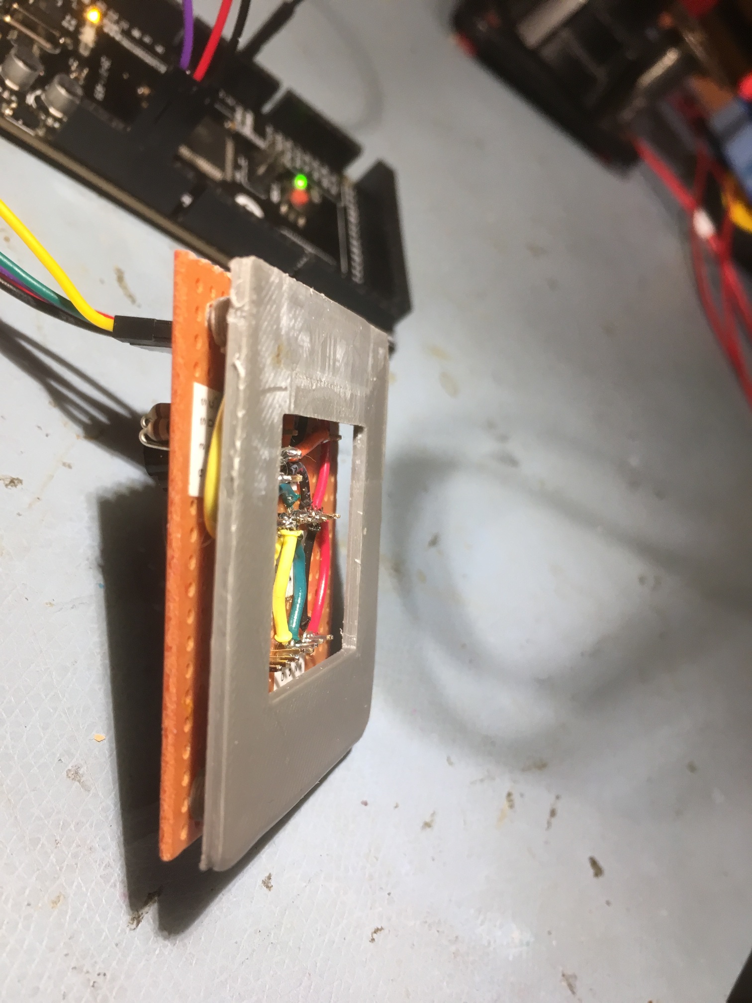
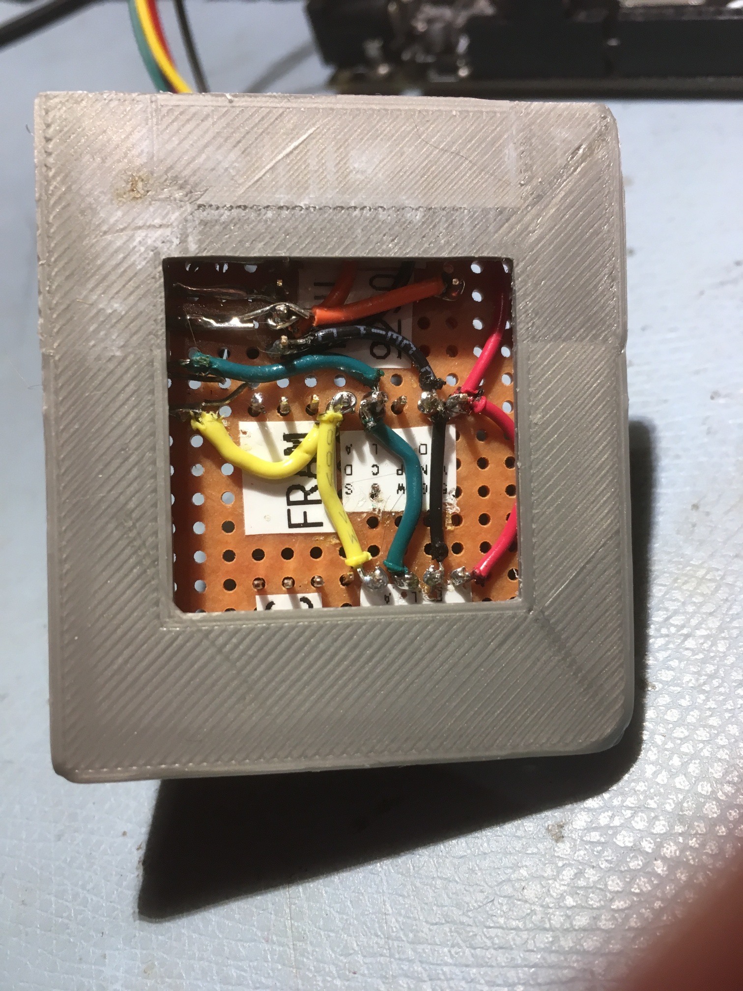
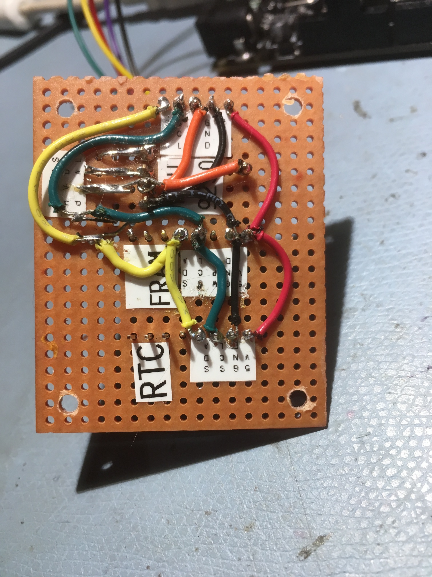
Stay tuned!
Frank