#include <Wire.h>
#include "MyAdafruit_FRAM_I2C.h"
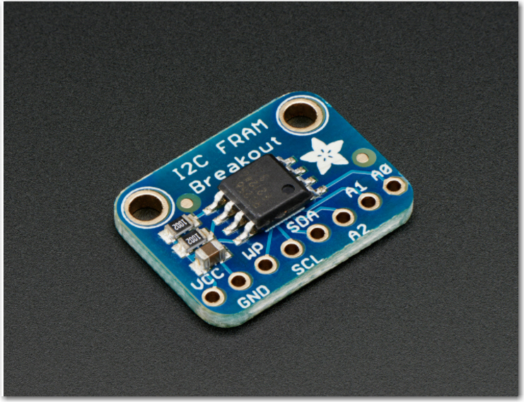
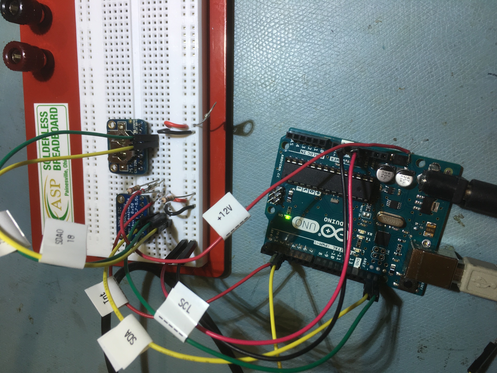
/* Example code for the Adafruit I2C FRAM breakout */
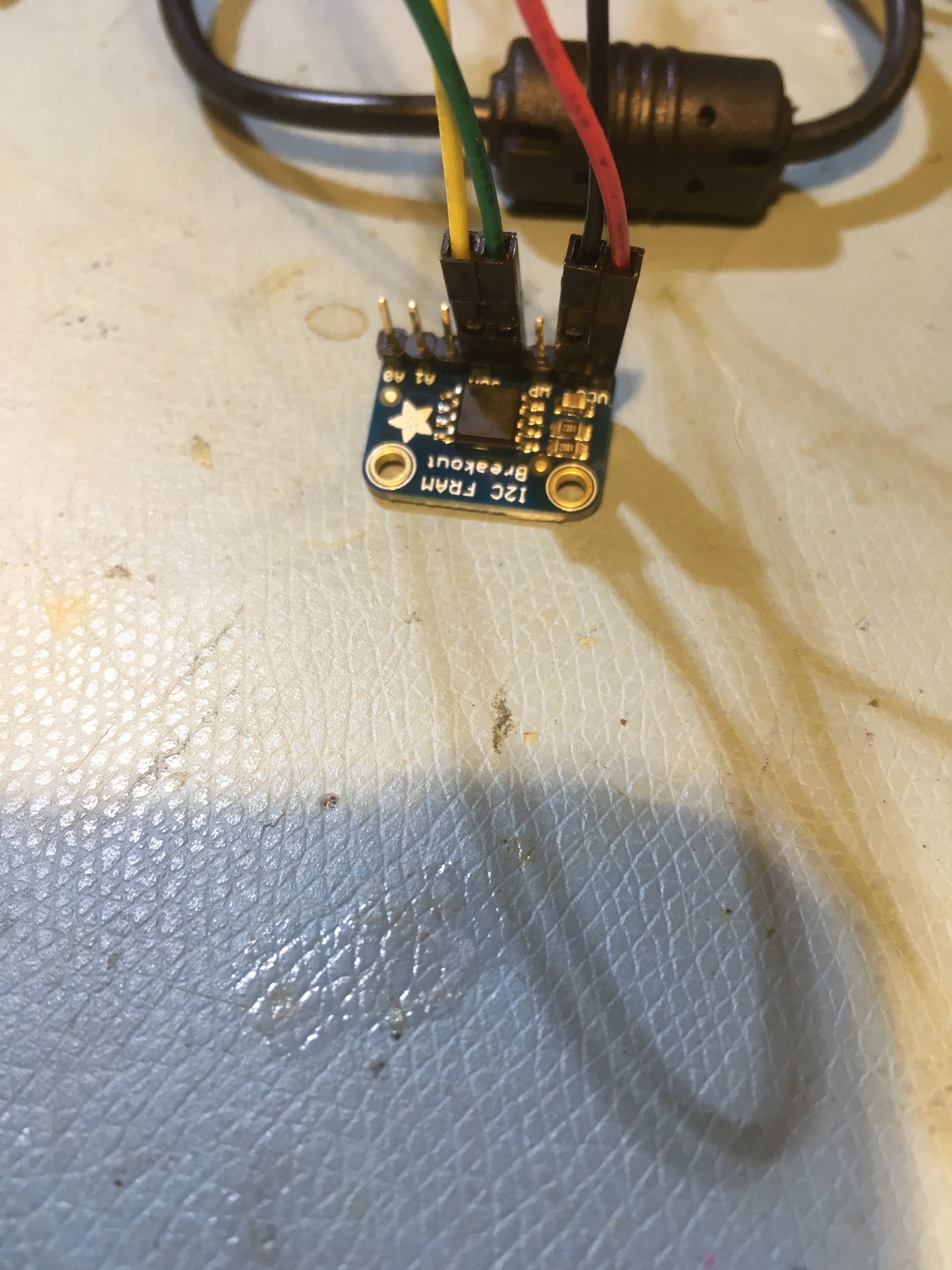
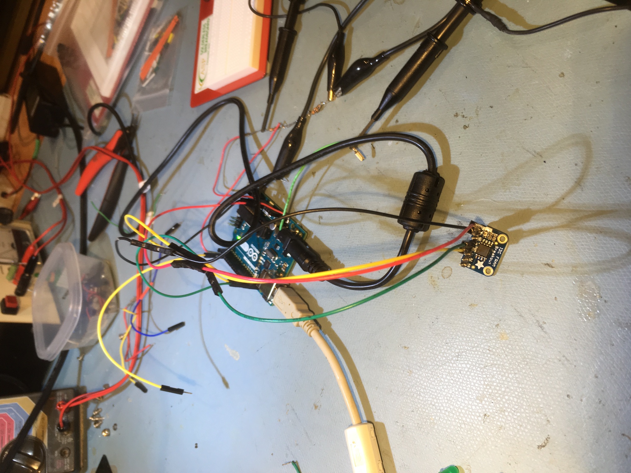
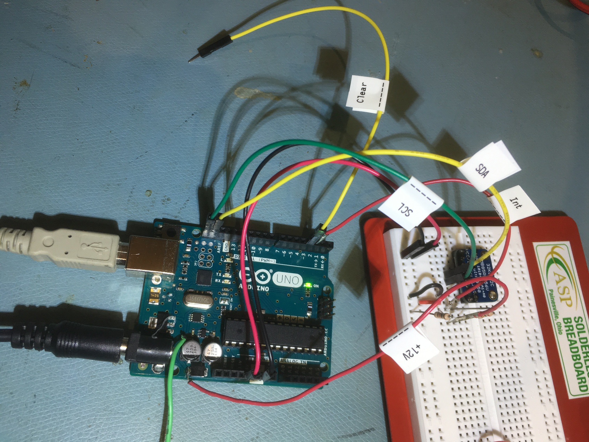
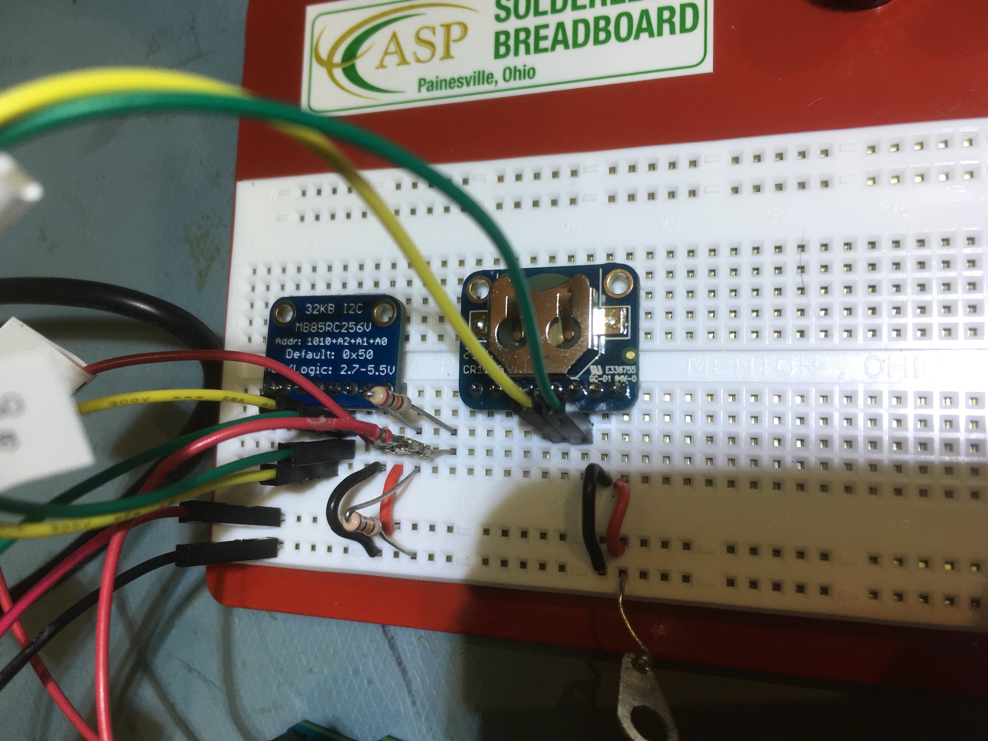
/* Connect SCL to analog 5
Connect SDA to analog 4
Connect VDD to 5.0V DC
Connect GROUND to common ground */
MyAdafruit_FRAM_I2C fram = MyAdafruit_FRAM_I2C();
uint16_t framAddr = 0;
volatile uint8_t testval;
const int InterruptPin = 2;
const int RestartCountAddr = 0x0;
volatile byte state = LOW;
byte last_state = state;
const byte ledPin = 13;
const int CLEAR_FRAM_PIN = 3;
const int NUM_LOCS_TO_CLEAR = 100;
int nextFramWriteAddr = 2; //addr 0 reserved for restart count, addr 1 is unusable (don't know why)
const int NUM_TIMES_TO_DISPLAY = 10;
bool InSetup = true;
void setup(void)
{
Serial.begin(2000000);
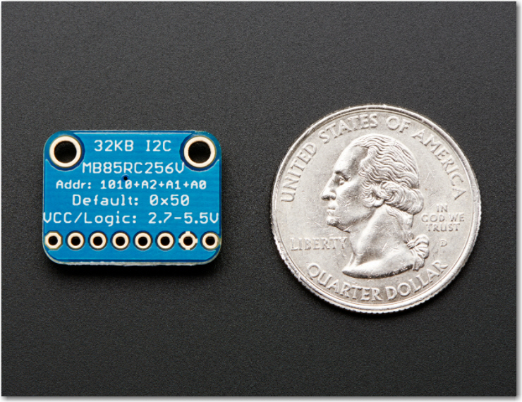
if (fram.begin()) { // you can stick the new i2c addr in here, e.g. begin(0x51);
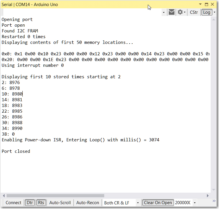
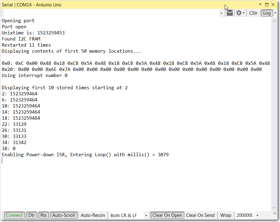
Serial.println("Found I2C FRAM");
}
else {
Serial.println("I2C FRAM not identified ... check your connections?\r\n");
Serial.println("Will continue in case this processor doesn't support repeated start\r\n");
}
// Read the first byte
fram.FRAM_I2C_readAnything(RestartCountAddr, testval);
Serial.print("Restarted "); Serial.print(testval); Serial.println(" times");
fram.FRAM_I2C_writeAnything(RestartCountAddr, testval + 1);
Serial.println("Displaying contents of first 50 memory locations... ");
uint8_t value;
for (uint16_t a = 0; a < 50; a++)
{
fram.FRAM_I2C_readAnything(a, value);
if ((a % 32) == 0) {
Serial.print("\n 0x"); Serial.print(a, HEX); Serial.print(": ");
}
Serial.print("0x");
if (value < 0x1)
Serial.print('0');
Serial.print(value, HEX); Serial.print(" ");
}
Serial.println();
pinMode(InterruptPin, INPUT_PULLUP);
pinMode(ledPin, OUTPUT);
pinMode(CLEAR_FRAM_PIN, INPUT_PULLUP);
int intnum = digitalPinToInterrupt(InterruptPin);
Serial.print("Using interrupt number "); Serial.println(intnum);
attachInterrupt(intnum, FRAM_ISR, FALLING);
interrupts();
//optionally clear FRAM locations
if (digitalRead(CLEAR_FRAM_PIN) == LOW)
{
Serial.print("Clearing "); Serial.print(NUM_LOCS_TO_CLEAR); Serial.println(" FRAM addresses...");
byte clearval = 0;
for (size_t i = 0; i < NUM_LOCS_TO_CLEAR; i++)
{
fram.FRAM_I2C_writeAnything(i, clearval);
}
//now read them back
DisplayMemory(NUM_LOCS_TO_CLEAR);
}
else
{
DisplayTimes(nextFramWriteAddr, NUM_TIMES_TO_DISPLAY);
}
Serial.print("Enabling Power-down ISR, Entering Loop() with millis() = "); Serial.println(millis());
InSetup = false; //enable power-down ISR
}
void loop(void)
{
digitalWrite(ledPin, state);
if (state != last_state)
{
Serial.println("Changed...");
last_state = state;
DisplayMemory(32);
DisplayTimes(nextFramWriteAddr, 10);
}
delay(100);
//Serial.print(millis()); Serial.print(": nextFramWriteAddr = "); Serial.println(nextFramWriteAddr);
}
void DisplayMemory(int lastAddr)
{
Serial.print("\nDisplaying memory locations 0 to "); Serial.println(lastAddr);
uint8_t value;
for (uint16_t a = 0; a < lastAddr; a++)
{
//value = fram.read8(a);
fram.FRAM_I2C_readAnything(a, value);
if ((a % 16) == 0)
{
Serial.print("\n 0x"); Serial.print(a, HEX); Serial.print(": ");
}
Serial.print("0x");
if (value < 0x1)
Serial.print('0');
Serial.print(value, HEX); Serial.print(" ");
}
Serial.println();
}
void DisplayTimes(int startaddr, int numtimes)
{
Serial.print("\nDisplaying first "); Serial.print(numtimes); Serial.print(" stored times starting at "); Serial.println(nextFramWriteAddr);
long value = 0;
for (uint16_t i = 0; i < numtimes; i++)
{
//value = fram.read8(a);
int addr = nextFramWriteAddr + i * sizeof(value);
int numbytes = fram.FRAM_I2C_readAnything(addr, value); //starts at addr 1
//Serial.print(i + 1); Serial.print(": "); Serial.println(value);
Serial.print(addr); Serial.print(": "); Serial.println(value);
}
}
void FRAM_ISR()
{
static boolean IsRunning = false;
if (IsRunning || InSetup) return; //we have been interrupted while already processing an interrupt - ignore this ocurrence
IsRunning = true;
//Depending on the interrupt source, you may need to clear the interrupt flag here. Most Arduino interrupts are self-clearing.
state = !state;
interrupts(); //re-enable interrupts so that interrupt-based functions can be used inside this function
//'infinite' loop (that is, until the Uno dies....)
while(1)
{
for (size_t i = 0; i < 1000; i++)
{
long timeMs = millis(); //interrupts are enabled, so this should work...
int numbyteswritten = fram.FRAM_I2C_writeAnything(nextFramWriteAddr, timeMs);
nextFramWriteAddr += numbyteswritten;
}
}
noInterrupts(); //turn off interrupts so we can't be interrupted while resetting our special variable
IsRunning = false;
}