Posted 1 November 2017
In my last post on this subject, I described my efforts to create a PCB for the charging module in my wall-following robot(s). I showed the hand-wired original, and the first (of three, so far) PCB versions. My circuit-checking skills are a bit deficient, so I keep finding ‘issues’ with the PCBs I received from Bay Area Circuits. It’s not their fault as they produced PCB’s exactly like I told them – apparently they don’t know about the RDM (Read Designer’s Mind) checkbox on their order form! 😉
In any case, the major problems I discovered on the first two revs are, kind-of, understandable for a PCB newbie like myself; I had the JST battery connectors switched, so Batt+ showed up on the PCB as Batt-, and the IRF-510 transistor holes were reversed as well. A bit of cut-and-jumper work solved the first problem, and simply turning the transistor around solved the second one. However, I really didn’t like leaving that as the ‘final solution’ so I splurged another $30 on a third rev with these problems fixed. These boards have not yet arrived, so in the meantime I continued testing on the current setup.
As the photo below shows, the finished and populated PCB has almost exactly the same dimensions as the hand-wired perfboard model. Since the perfboard version had several components mounted on the wiring side, arriving at the same dimensions with everything on one side is a definite plus!
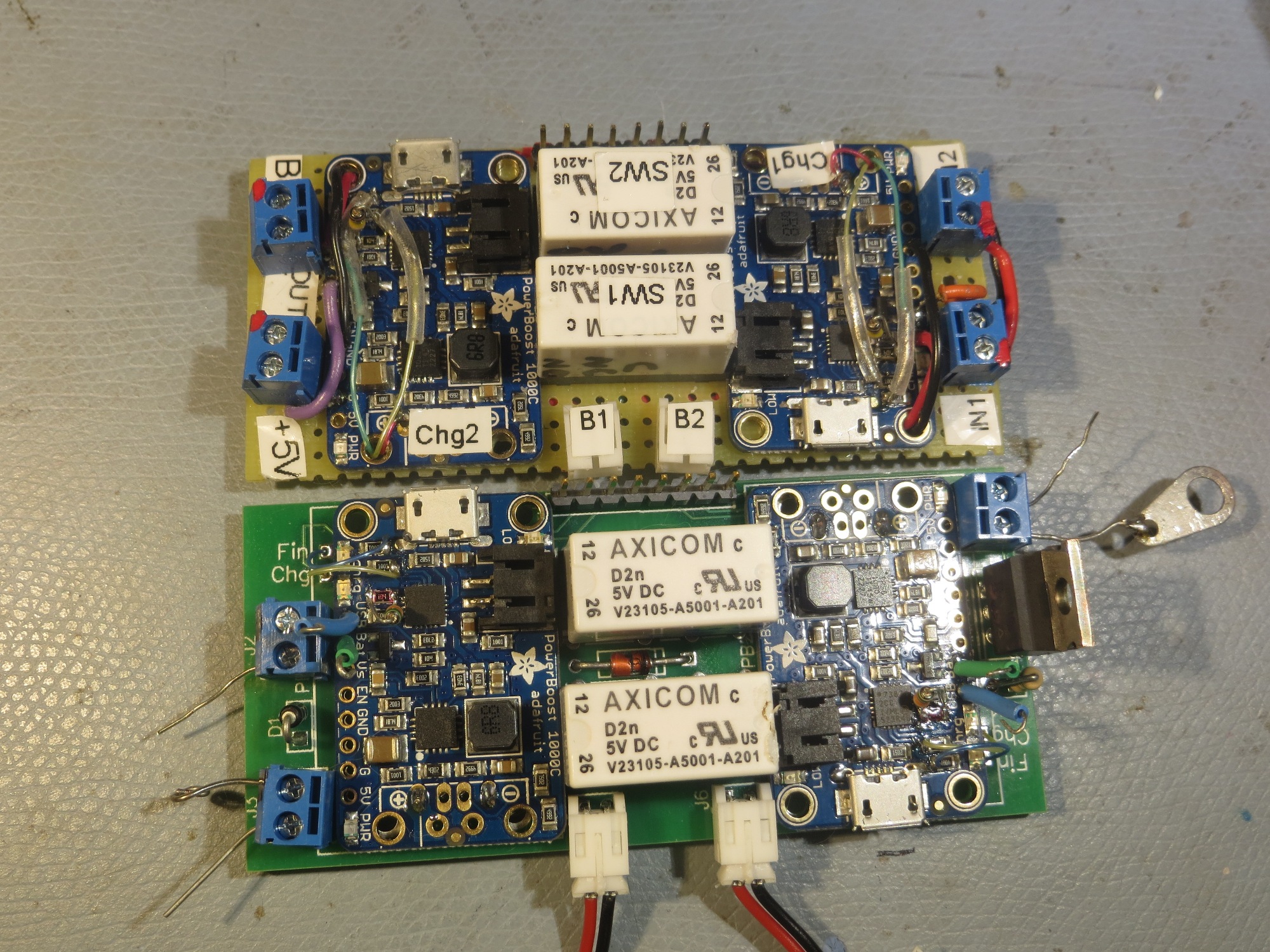
comparison between the hand-wired perfboard version and the PCB
After getting the PCB populated, I did some electrical testing, and somewhere along the way I think I managed to damage the boost regulator chip on one of the PowerBoost 1000C modules. And this is where I discovered my next major booboo – I had hard-wired the PB1000C’s to the PCB, and so now I couldn’t replace the damaged part without destroying the part, and probably the PCB too – oops!
07 December 2017 (Pearl Harbor Day) Update:
I received the latest (and hopefully, last!) batch of battery charger module PCB’s from Bay Area Circuits a week ago, but have been too busy with other things (mostly dealing with the new V3 robot chassis) to do much with it. So, today I started populating and testing the new charger module. As I mentioned before, one of the bigger mistakes I made on the previous version was to hard-wire the PowerBoost 1000C’s onto the PCB, making it almost impossible to replace if it failed (and, as I learned from the Adafruit forums they can be easily damaged if they are powered up without a battery attached). So, this time I soldered female headers onto the PCB and male headers onto the charger modules, making them easy to replace if needed.

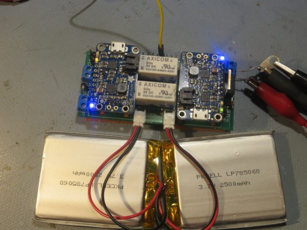
New charger module with some test batteries attached
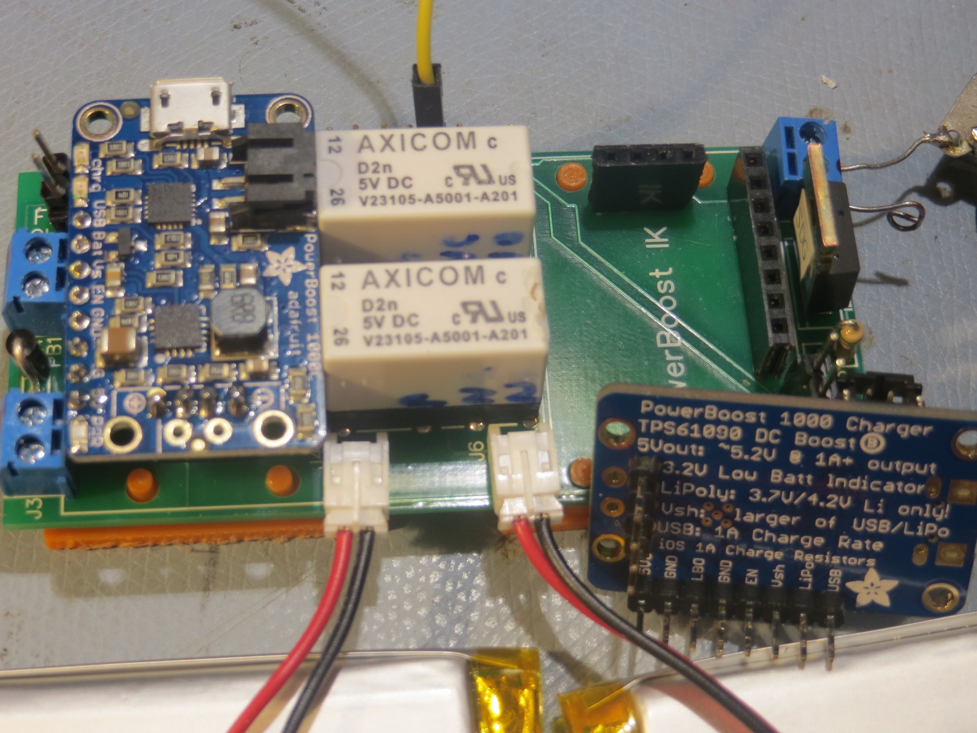
Charger module showing PowerBoost 1000C header arrangement
The next step will be to test the module’s ability to manage the robot’s battery stack. I plan to simulate the robot load with a 500 mA resistive load, and simulate the actual battery stack with the two smaller 2500 mAH batteries shown in the above photos. I’ll simulate the robot with an Arduino, programmed to print out time-stamped readings of the robot power voltage (actually 1/3 of the robot power voltage, but what’s a scaling factor between friends?).
Stay tuned!
Pingback: Wall-E2 battery charger module testing, Part I - Paynter's Palace