Posted 15 December 2017
For the last couple of months I have been working on the battery subsystem for my Wall-E2 autonomous wall-following robot. Along the way I upgraded the robot chassis to provide more room for the on-board charger & battery pack, and created a PC board design for the module that charges the 2-cell LiPo stack in parallel and then switches to a serial configuration to run the motor. This post describes the first part of a testing program to validate the performance of the Adafruit PowerBoost 1000C charger module, and the idea of switching seamlessly from charging to powering a load.
By way of background for this post, I ran into some difficulties when I tried to integrate the full-up 2-cell, 2-PB1000C battery pack/charger combination into my Wall-E2 robot, and troubleshooting the problems using the complete operating system software proved to be somewhat tedious, I decided to start at the other end with a very simple test program running on an Arduino Uno, and a single PB1000C charger.
The Arduino test program is very simple; when it is initialized, it checks the battery voltage to see if is above or below a preset threshold. If above, it energizes a DPDT relay to connect the battery to a 15Ω load; if below, it de-energizes the relay, which disconnects the battery from the load and also connects 5V to the ‘USB’ (5V input) terminal of the PB1000C, thereby charging the battery. After that, the program alternately switches the battery between the load and charging states, recording the battery voltage every four seconds.
Battery Testing Hardware

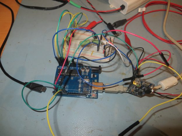
Arduino Uno and test circuit. Note the yellow ‘charging’ LED on PowerBoost 1000C shown at middle right
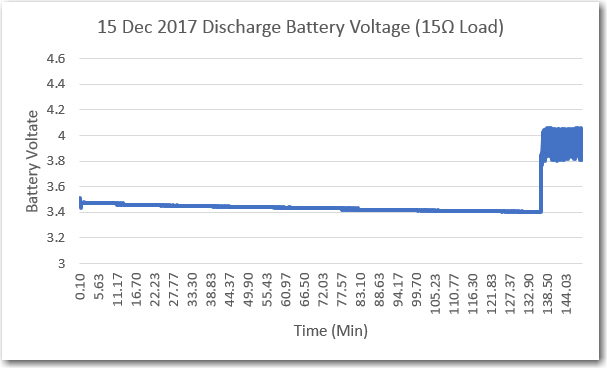
After working the inevitable bugs out of the Arduino program, I got some reasonable battery cycling data, as shown in the following plots. The battery used in all these tests was a PKCell LP795060 LiPo cell, rated for 3.7V and 2500mAH. It is rated for about 5hrs at 0.2C discharge, but I was only seeing about 3hrs at 0.1C, most probably because I was terminating the discharge at 3.4V rather than the 2.75V used in the discharge tests.
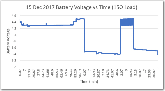
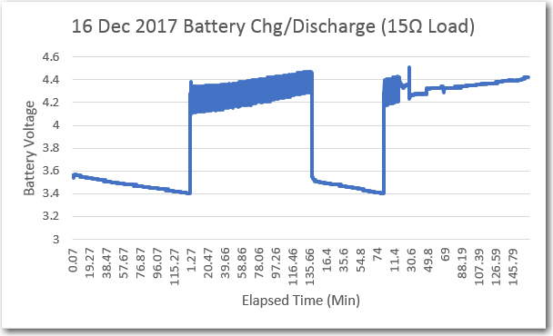
Two complete chg/discharge cycles

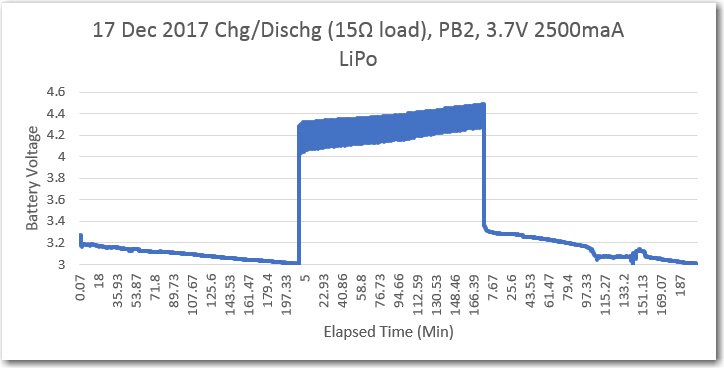
Chg/Dischg cycles using PB2 (same battery as previous tests). Short cycles may imply battery wear-out
After the last test above, I was concerned that either the PowerBoost 1000C was not operating properly, or the battery itself was failing, or both. So, I changed the discharge termination threshold from 3.4 to 3.0V to be more consistent with the 2.75V cutoff used by the battery manufacturer. After making this change only, I got the following plot
Charge/discharge cycles after changing the discharge termination threshold from 3.4 to 3.0V
As can be seen from the above plot, the discharge and charge times were extended dramatically. Discharge (at approximately 220 mA or 0.1C) took well over 3hrs, and charge took about the same amount of time. So, it appears that both the PowerBoost 1000C modules are still working OK even after the abuse I put them through by plugging them into a PCB with wiring errors ;-).