Posted 17 November 2017
In my ongoing quest to give Wall-E2 a bigger/roomier ride, I am continuing the process of moving all Wall-E2’s stuff to the new chassis, and modifying the charging station to work properly with the new wide-body model.
Second Deck Sensors:
Even with the wider footprint, there’s not enough real estate to easily mount the three distance sensors (LIDAR for forward distance, and acoustic for left/right distance). I could shoe-horn it all in, but it would look messy and would leave all Wall-E2’s electronics exposed to potential damage from furniture, cats, careless humans, etc. So I decided to transplant the second deck, complete with all the sensors, to the new chassis. This looked to be a real PITA, until I let go of the notion that the 60mm stand-offs had to remain in the same locations. Once I did that, things got a lot easier 😉
IR Homing Module:
This was a straightforward transplant, especially since all the detection/demodulation is being
3D printed spacers for the motor controller PCBs
done by a Teensy 3.2 physically attached to the sunshade. All I had to do was drill the mounting holes, add two more press-fit nuts, and screw on the module.
Arduino Mega Processor and Motor Controllers:
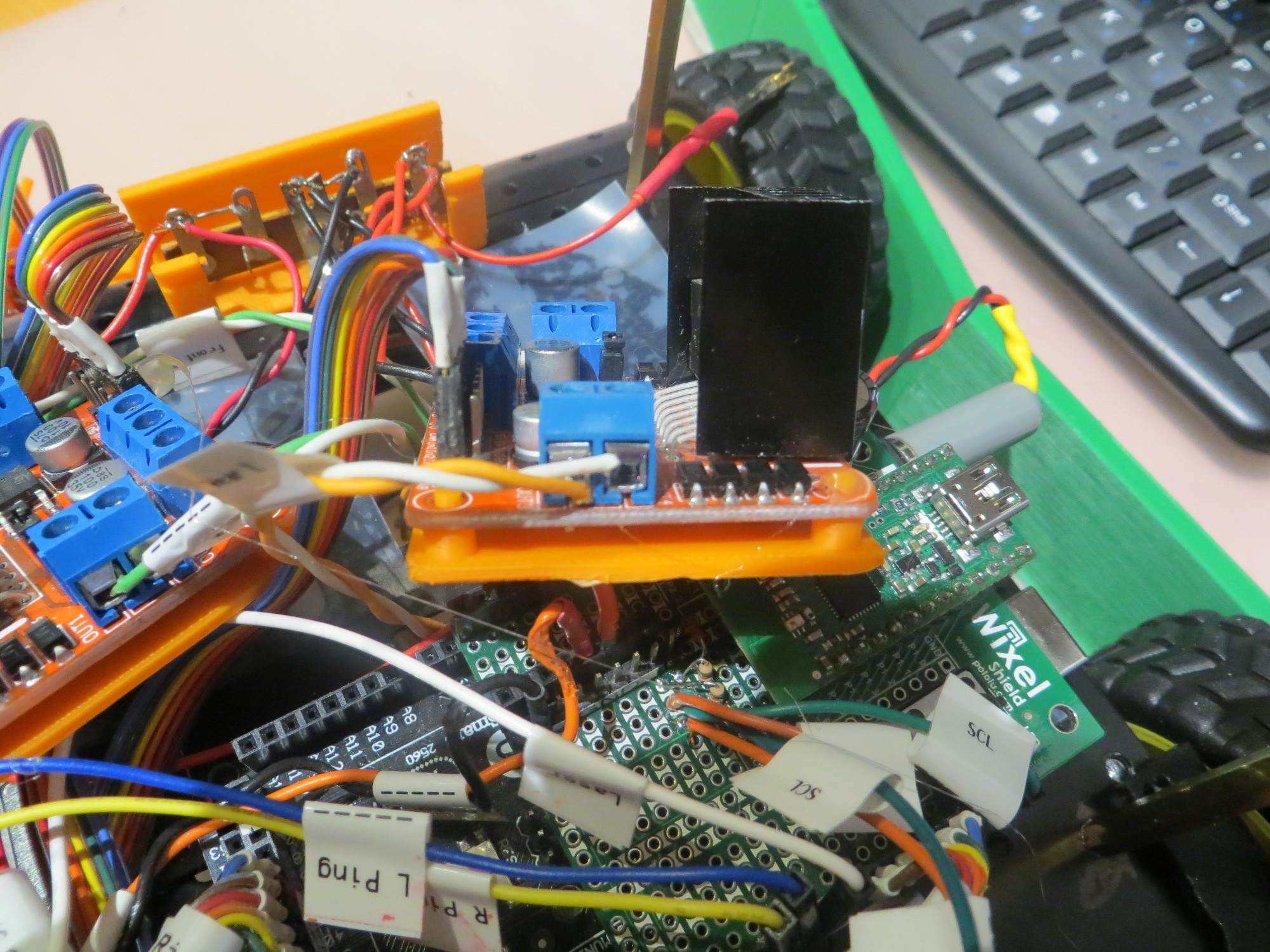
These two items came over as a group, as that way I didn’t have to disconnect anything – my kind of transplant! However, while I was at it, I decided to neaten things up a bit by printing spacers for the motor controllers; this isolates the underside of the PCBs from the metal chassis, and provides a nice flat surface for mounting the controllers to the chassis with double-sided tape – a win-win-win (the last ‘win’ was because I got to use my 3D printer some more!)
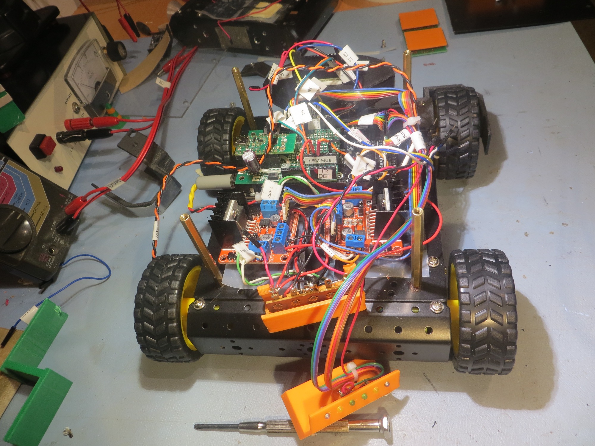
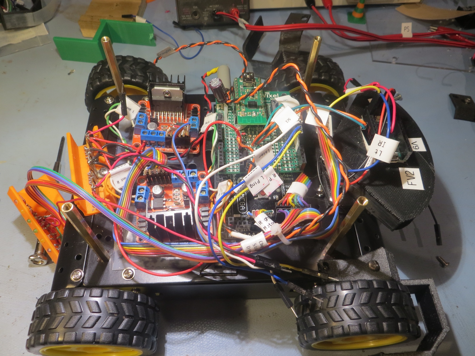
Arduino Mega processor, motor controllers, rear taillight assembly, and IR homing module transplanted
Charging Station Modifications:
I was not looking forward to modifying the charging station to work with the new wider chassis. The charging station electronics assembly is non-trivial, and it would be a real PITA If I had to reprint the frame and transfer all the electronics. Fortunately for me, this turned out not to be the case. By a happy coincidence, the distance from the right-hand guide rail to the center of the power receptacle was exactly the same for the new chassis as for the old one, so all I had to do was re-position the left-hand rail to accommodate the wider tread spacing. Well, there was one minor glitch – the charging station has two physical stops, and the one that mated with the left-hand wheel guard on the old chassis now didn’t hit anything, so I had to print a small 5mm thick spacer and double-sided tape it to the front of the existing stop.
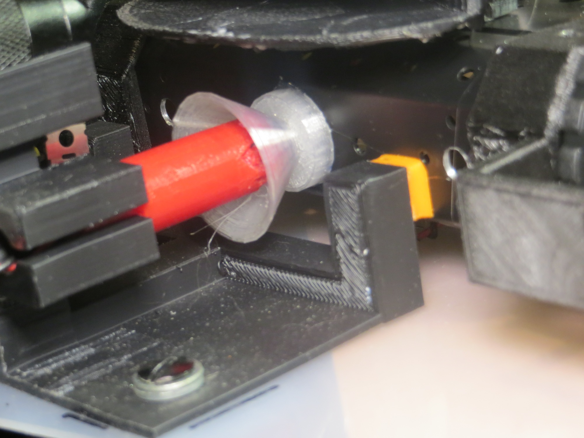
Closeup of the spacer for the right-hand charging station stop
Front view showing left and right charging station stops (with spacer added to right one)
18 November 2017 Update:
I’ve got almost everything transplanted over now, as shown in the following photos:
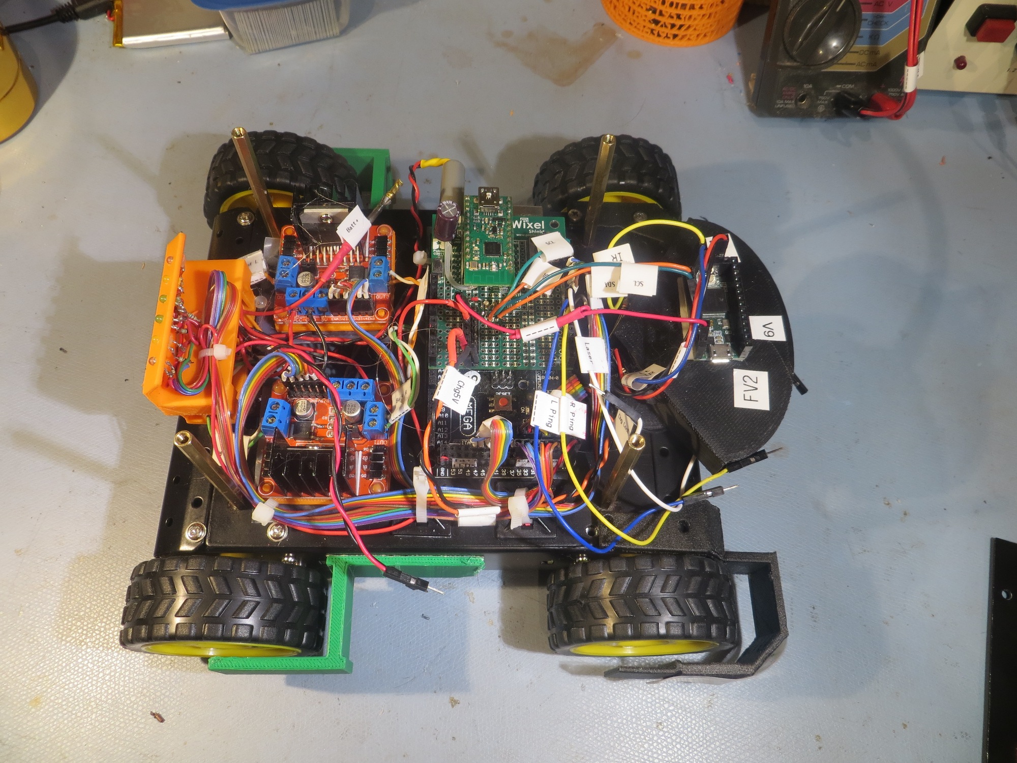
Side view without the sensor deck, showing that all modules are in place
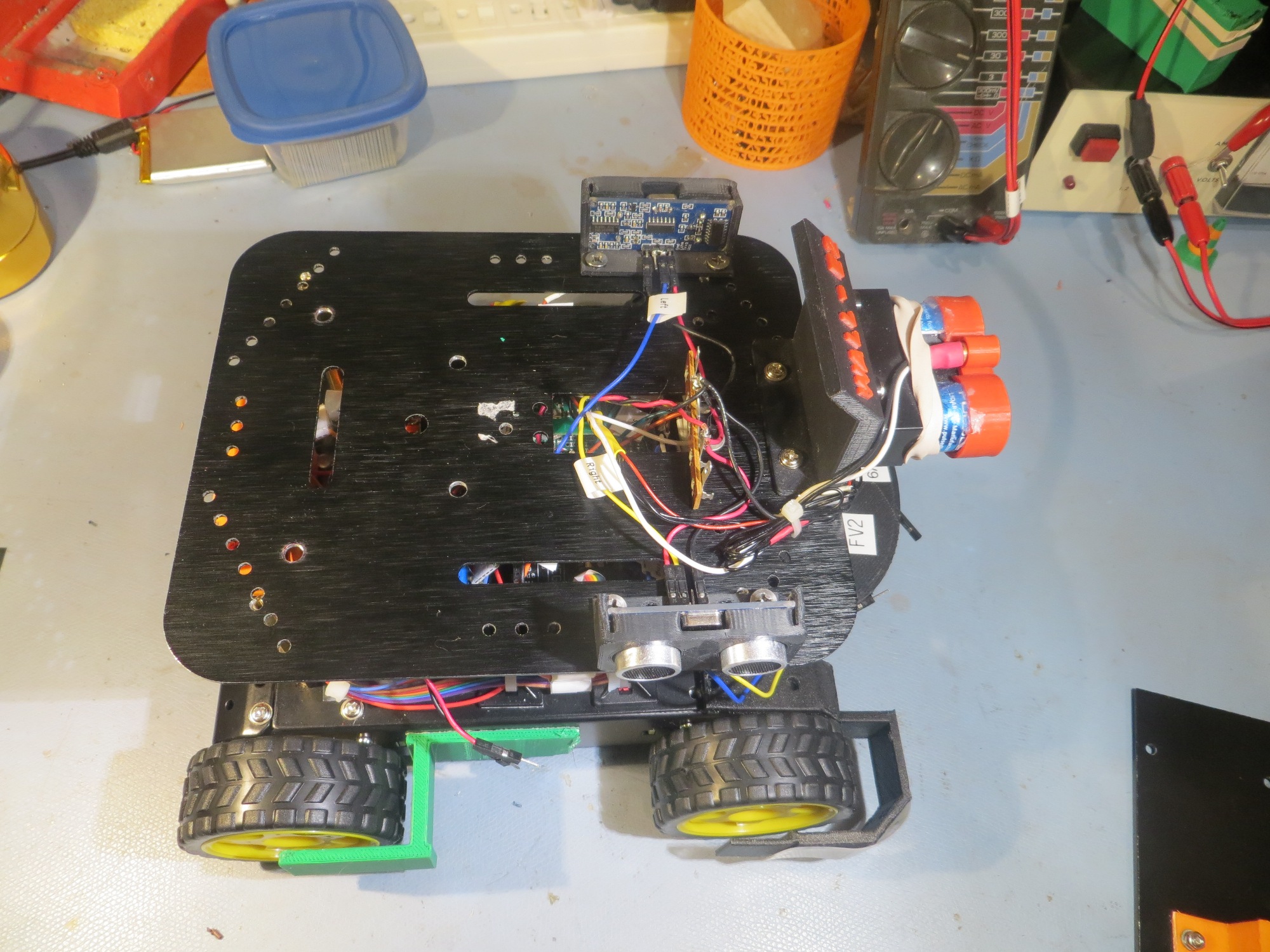
Side view showing the sensor deck in place.
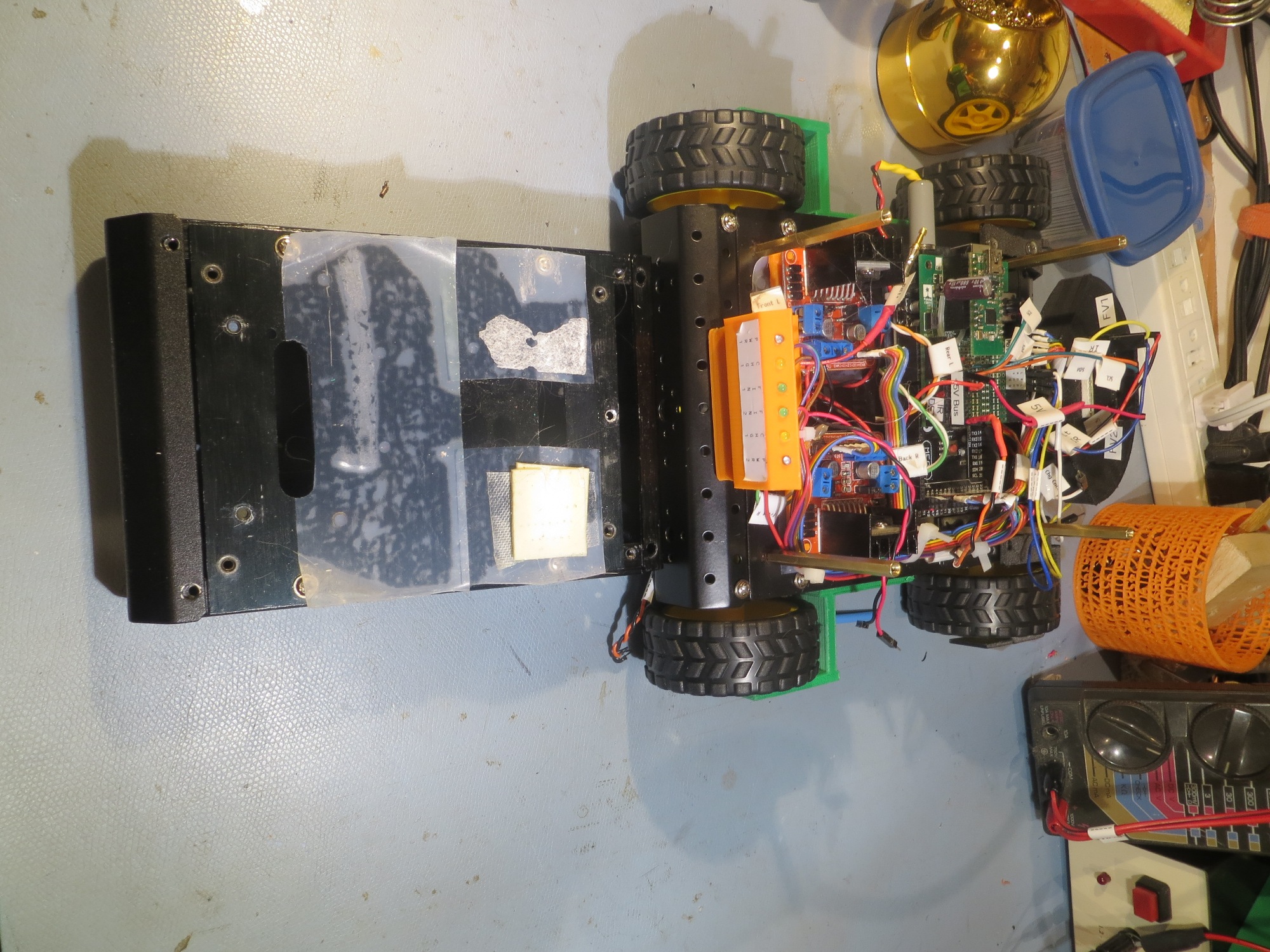
end-on view showing the difference between the old and new chassis dimensions
There’s still a ton of work to be done; The latest version of the charger PCB still hasn’t arrived from Bay Area Circuits, so I still need to do all that, and then wire the finished module into the battery compartment. Also, I’m having to redo the front bumper guards, as I have found they are somewhat fragile due to the way in which they were printed – bummer! However, it shouldn’t be too long before I can take the new model out for a spin! ;-).
Stay tuned!
Frank