Monthly Archives: November 2017

A New Chassis For Wall-E2, Part II

Posted 17 November 2017

In my ongoing quest to give Wall-E2 a bigger/roomier ride, I am continuing the process of moving all Wall-E2’s stuff to the new chassis, and modifying the charging station to work properly with the new wide-body model.

Second Deck Sensors:

Even with the wider footprint, there’s not enough real estate to easily mount the three distance sensors (LIDAR for forward distance, and acoustic for left/right distance).   I could shoe-horn it all in, but it would look messy and would leave all Wall-E2’s electronics exposed to potential damage from furniture, cats, careless humans, etc.   So I decided to transplant the second deck, complete with all the sensors, to the new chassis.   This looked to be a real PITA, until I let go of the notion that the 60mm stand-offs had to remain in the same locations. Once I did that, things got a  lot easier 😉

IR Homing Module:

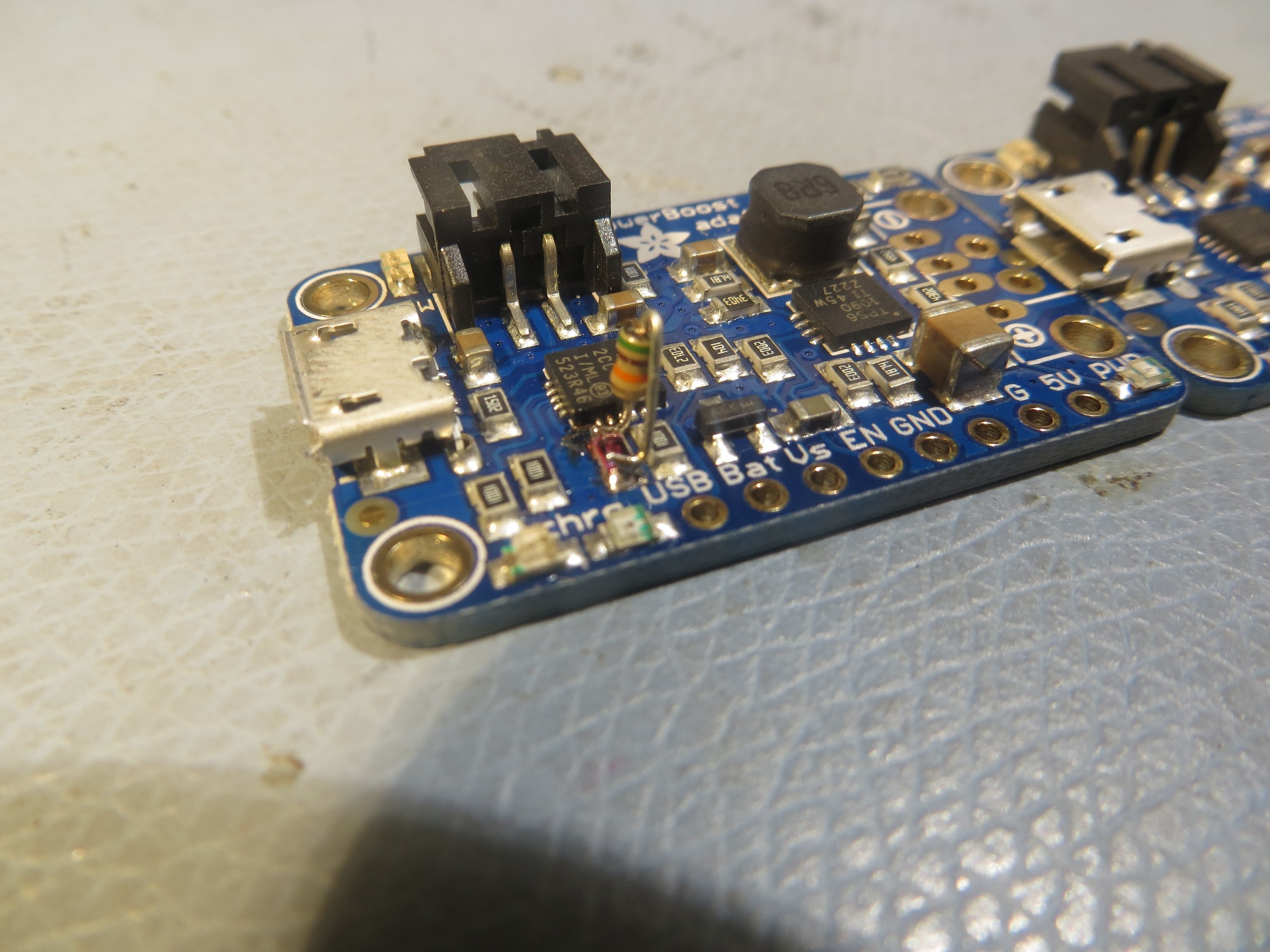
This was a straightforward transplant, especially since all the detection/demodulation is being

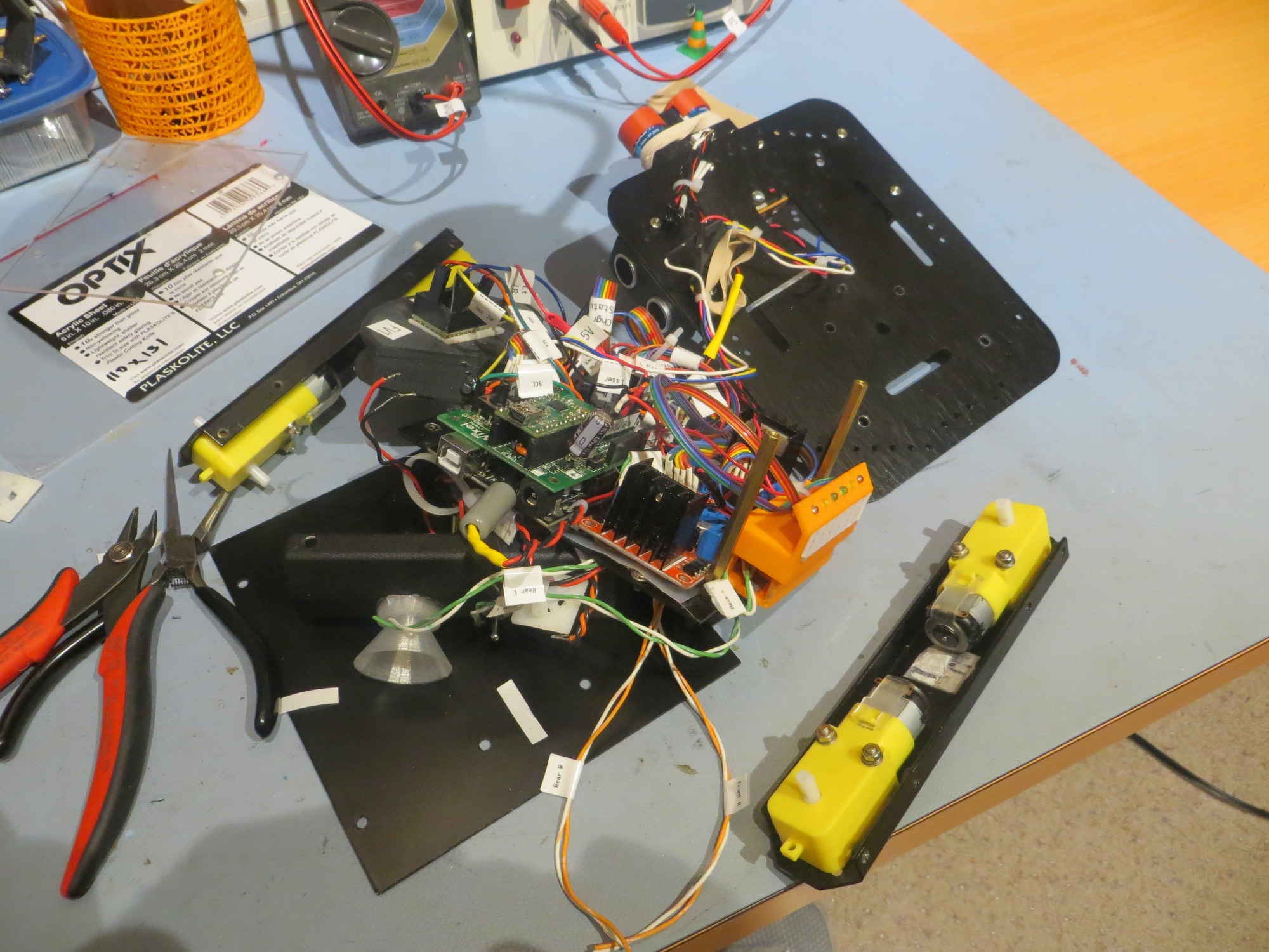
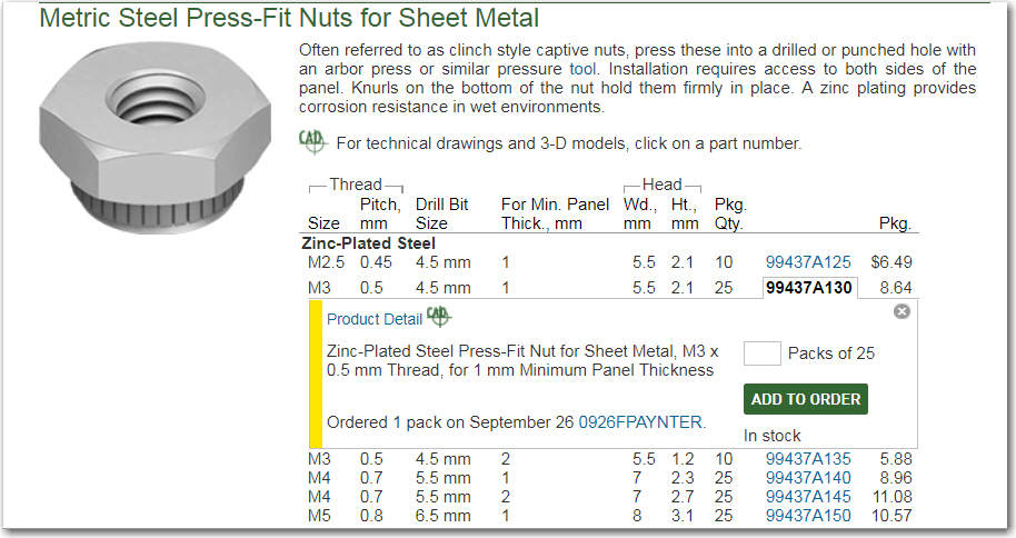
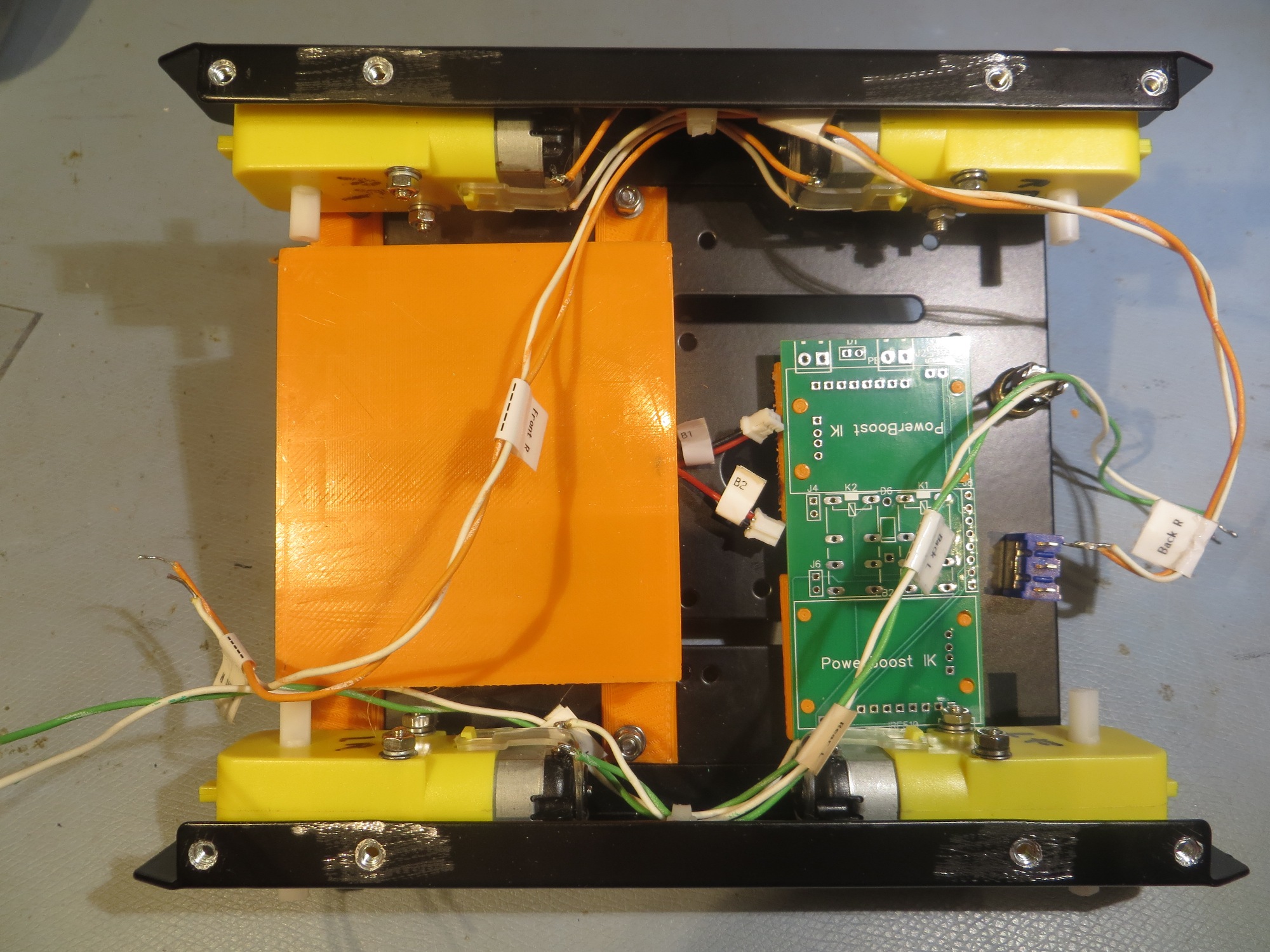
3D printed spacers for the motor controller PCBs

done by a Teensy 3.2 physically attached to the sunshade. All I had to do was drill the mounting   holes, add two more press-fit nuts, and screw on the module.

Arduino Mega Processor and Motor Controllers:

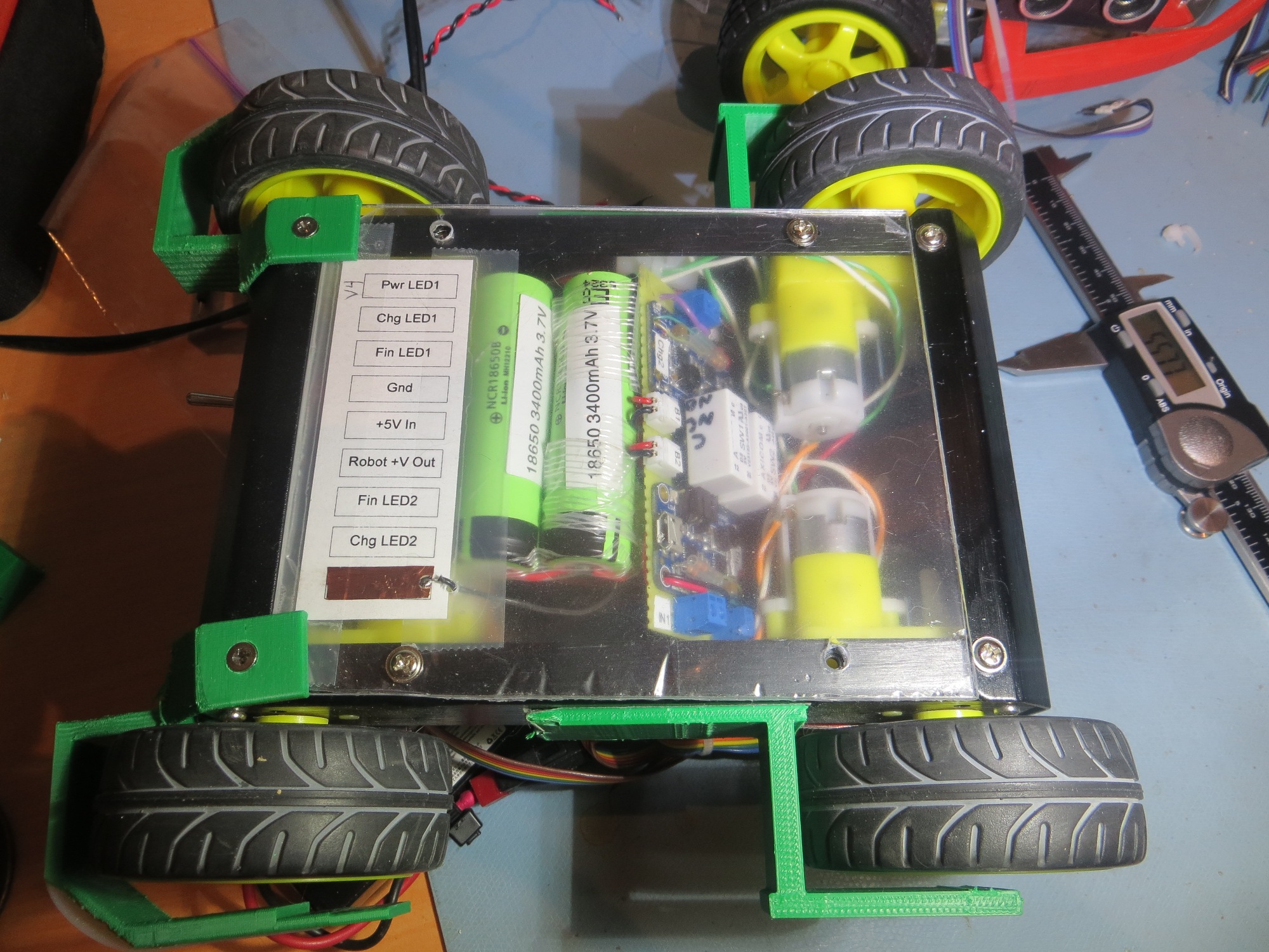
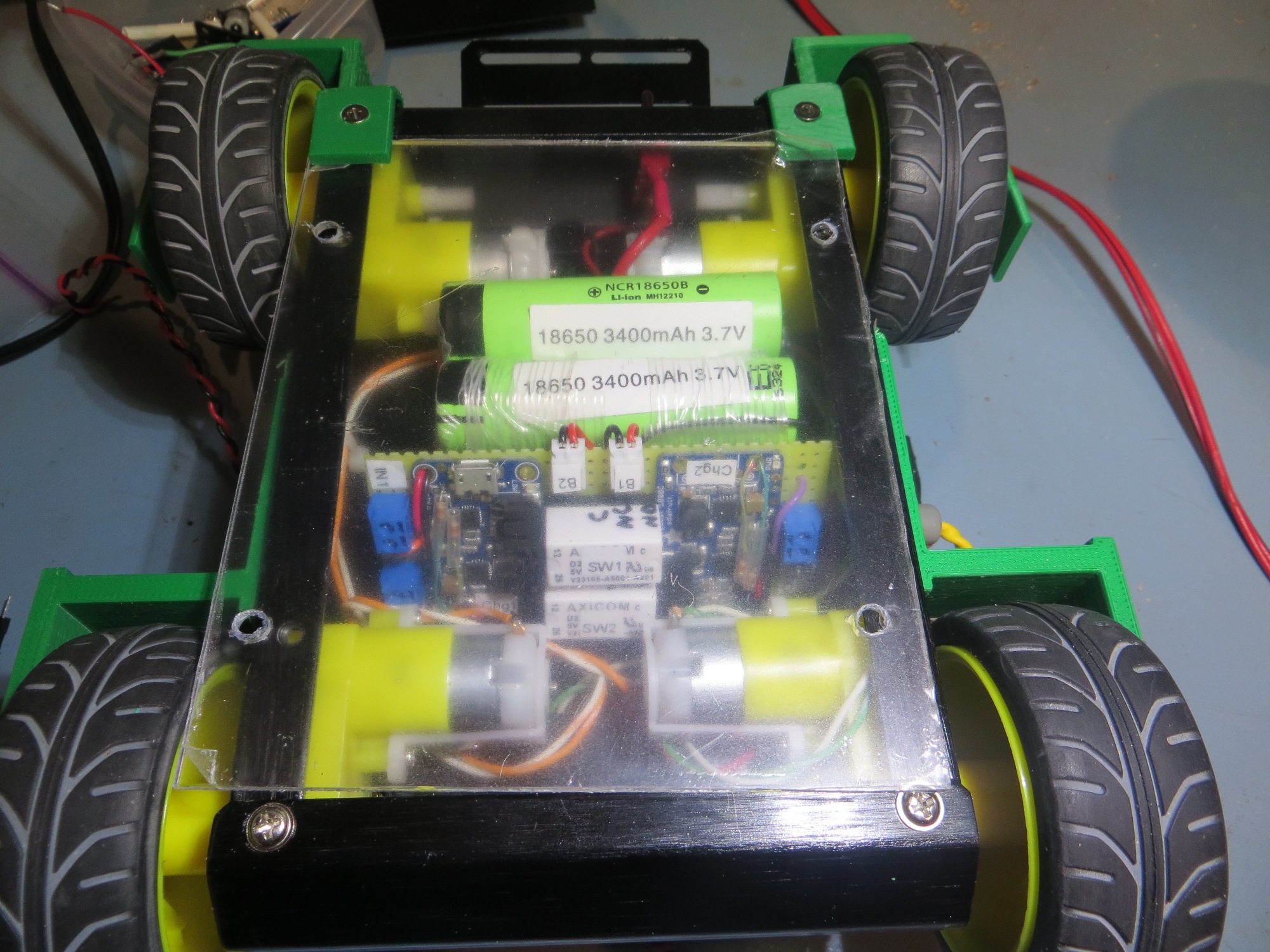
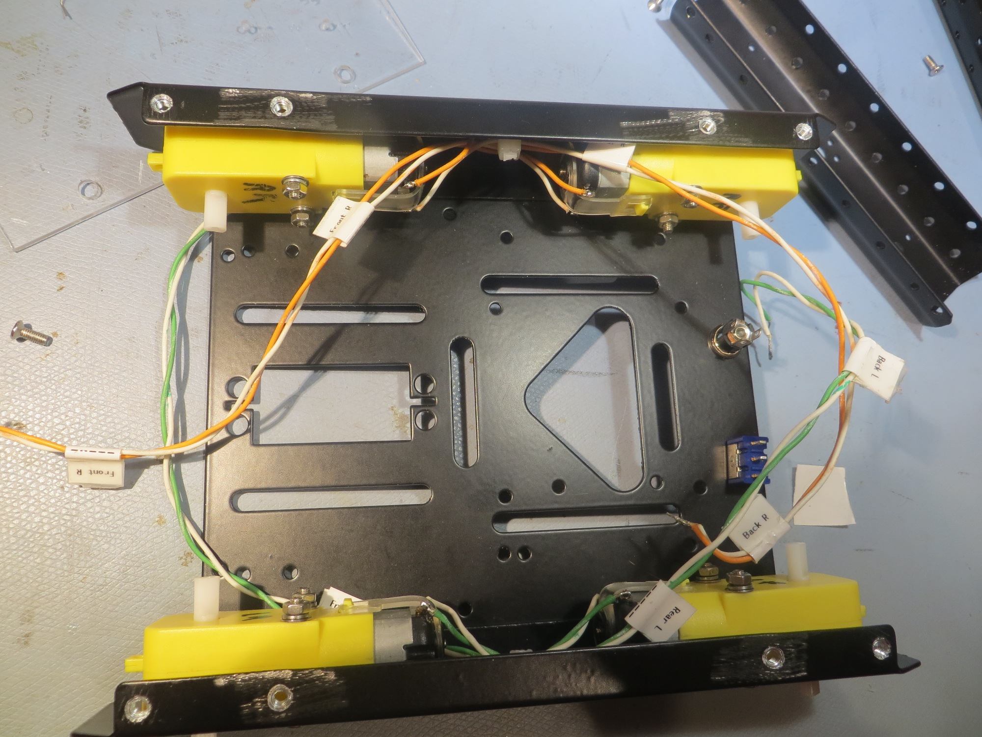
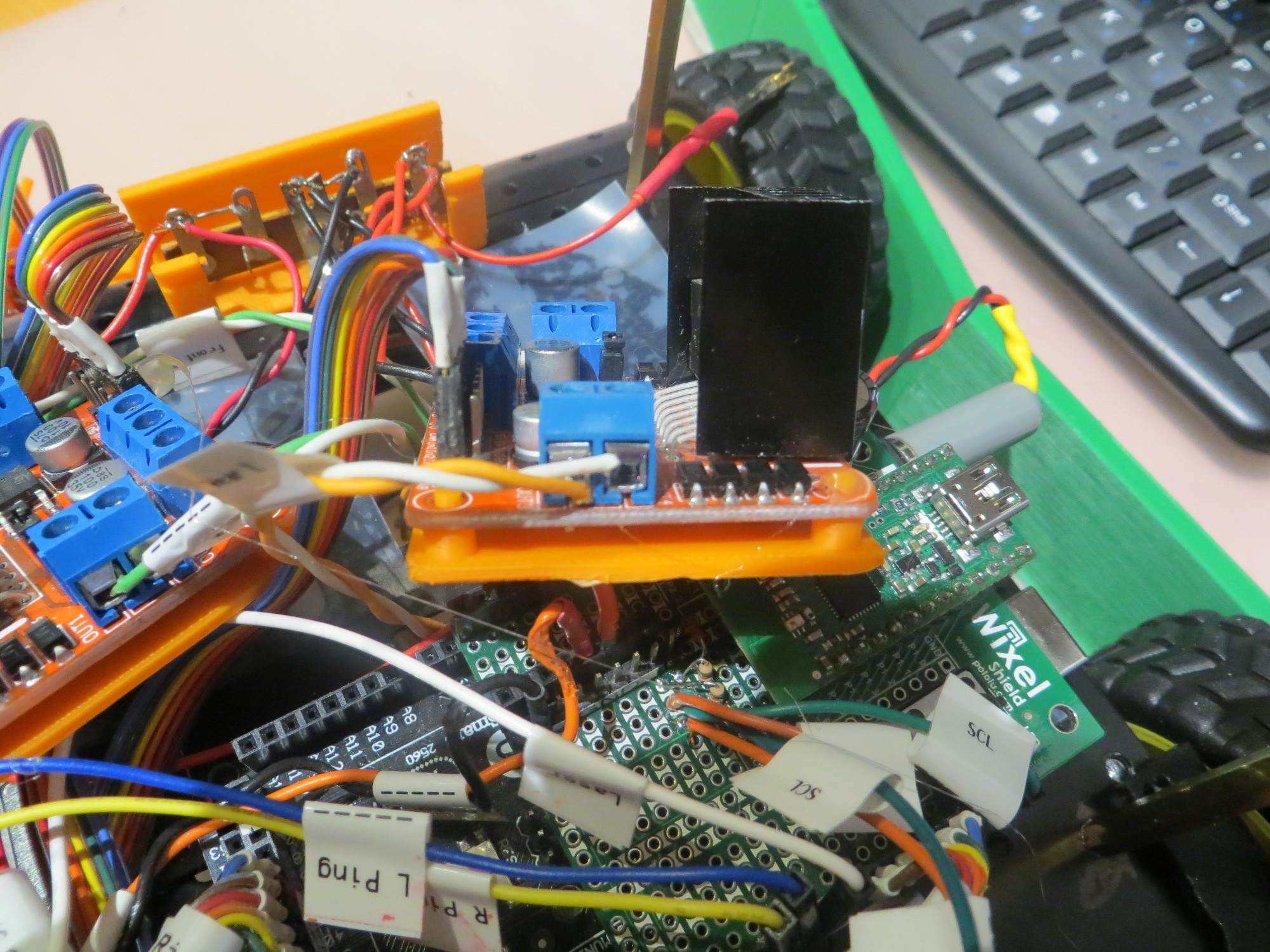
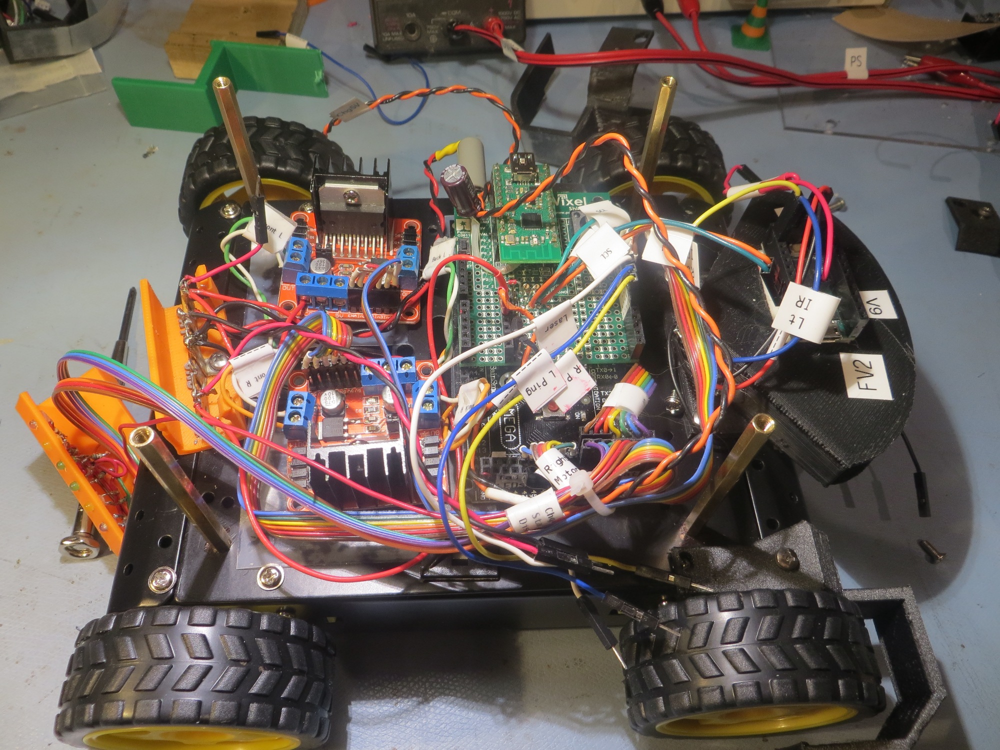
These two items came over as a group, as that way I didn’t have to disconnect anything – my kind of transplant!   However, while I was at it, I decided to neaten things up a bit by printing spacers for the motor controllers; this isolates the underside of the PCBs from the metal chassis, and provides a nice flat surface for mounting the controllers to the chassis with double-sided tape – a win-win-win (the last ‘win’ was because I got to use my 3D printer some more!)

Arduino Mega processor, motor controllers, rear taillight assembly, and IR homing module transplanted

Charging Station Modifications:

I was  not  looking forward to modifying the charging station to work with the new wider chassis.   The charging station electronics assembly is non-trivial, and it would be a real PITA If I had to reprint the frame and transfer all the electronics. Fortunately for me, this turned out not to be the case.    By a happy coincidence, the distance from the right-hand guide rail to the center of the power receptacle was exactly the same for the new chassis as for the old one, so all I had to do was re-position the left-hand rail to accommodate the wider tread spacing. Well, there was one minor glitch – the charging station has two physical stops, and the one that mated with the left-hand wheel guard on the old chassis now didn’t hit anything, so I had to print a small 5mm thick spacer and double-sided tape it to the front of the existing stop.

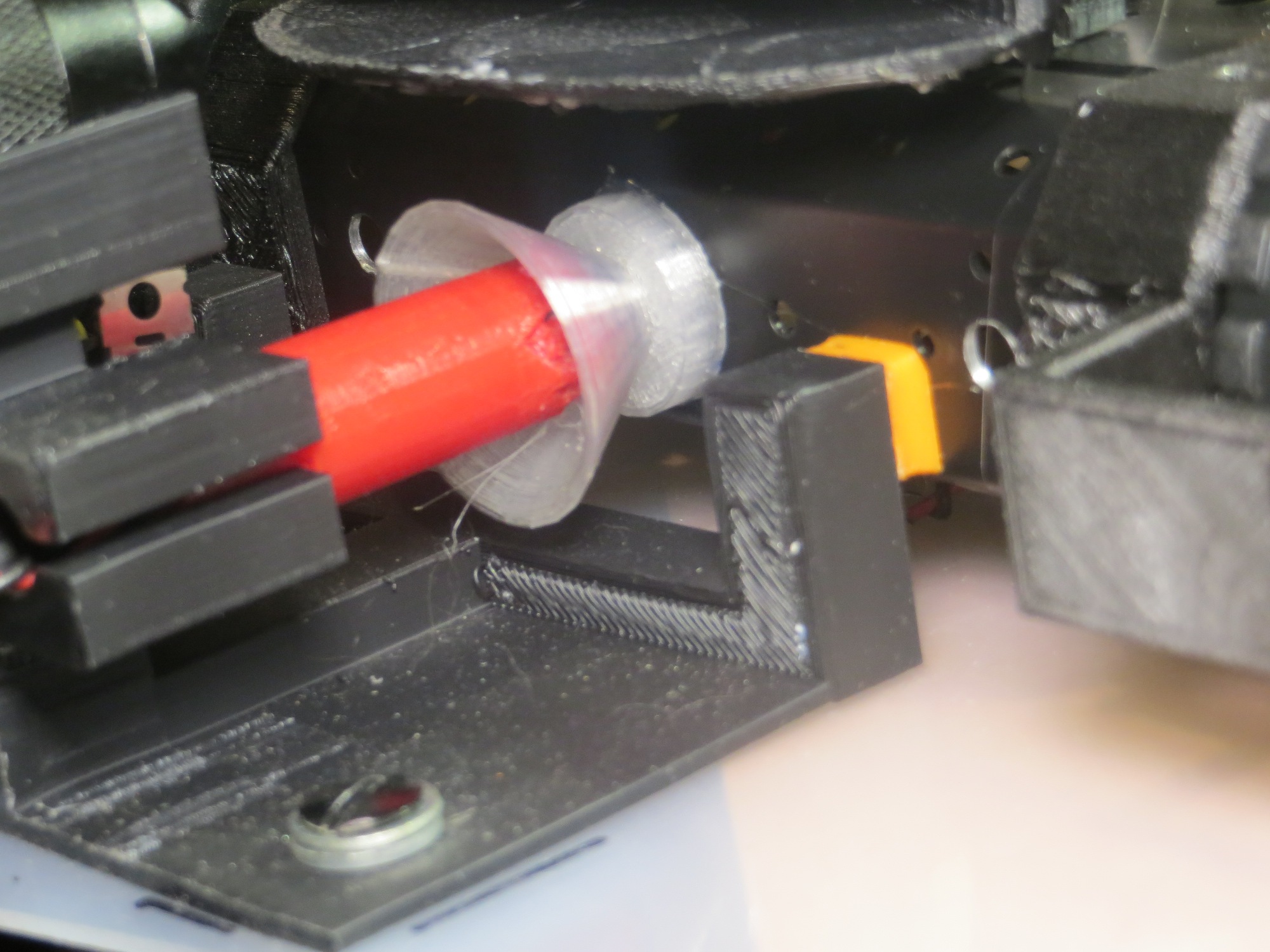
Closeup of the spacer for the right-hand charging station stop

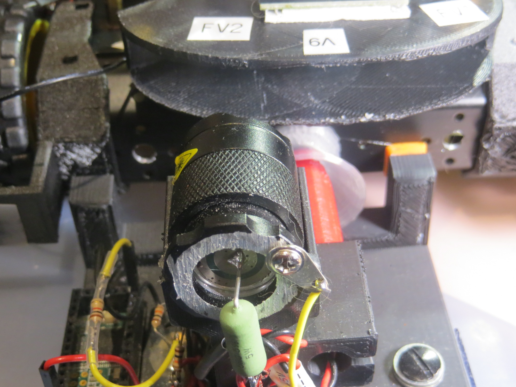
Front view showing left and right charging station stops (with spacer added to right one)

18 November 2017 Update:

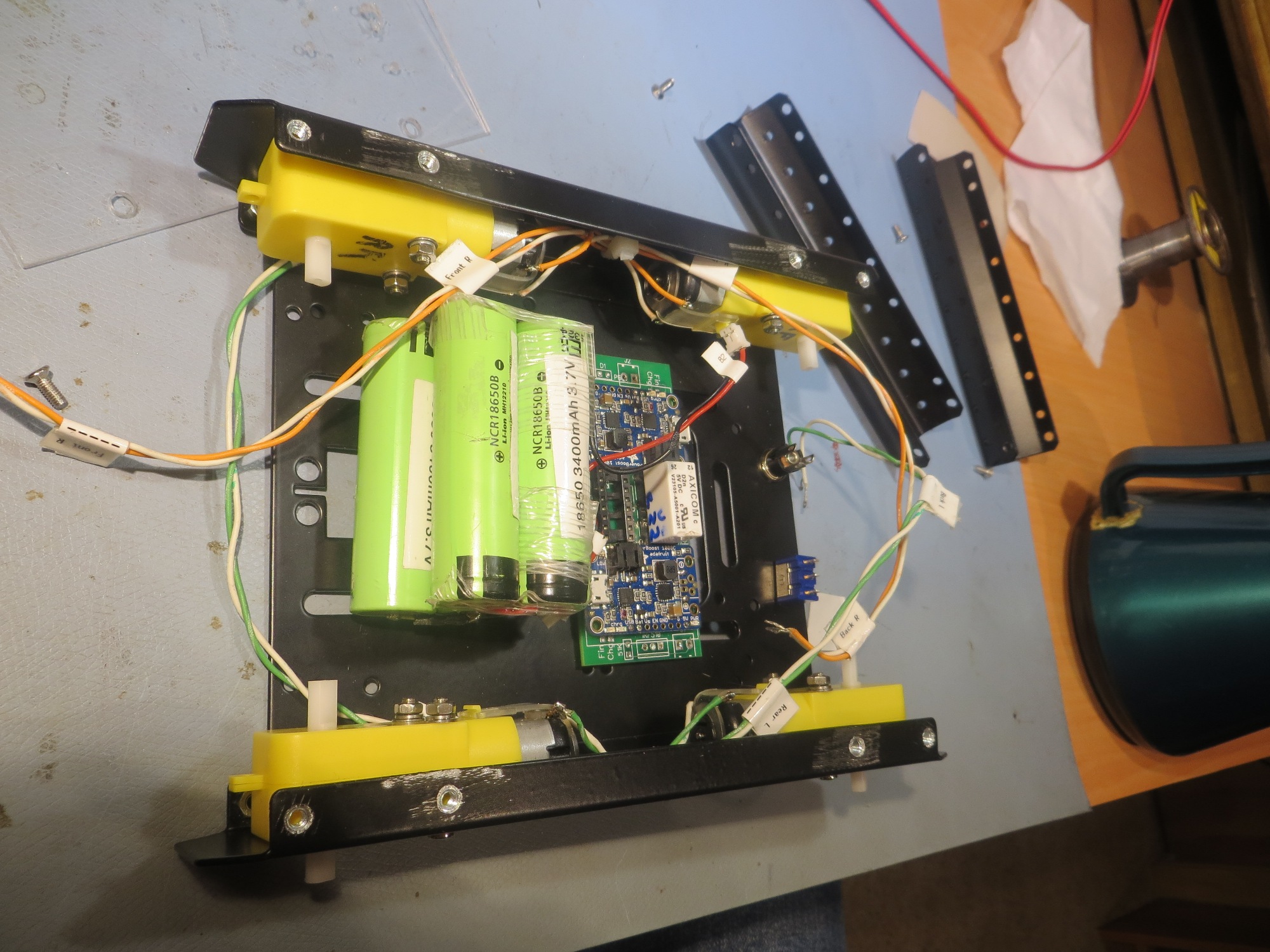
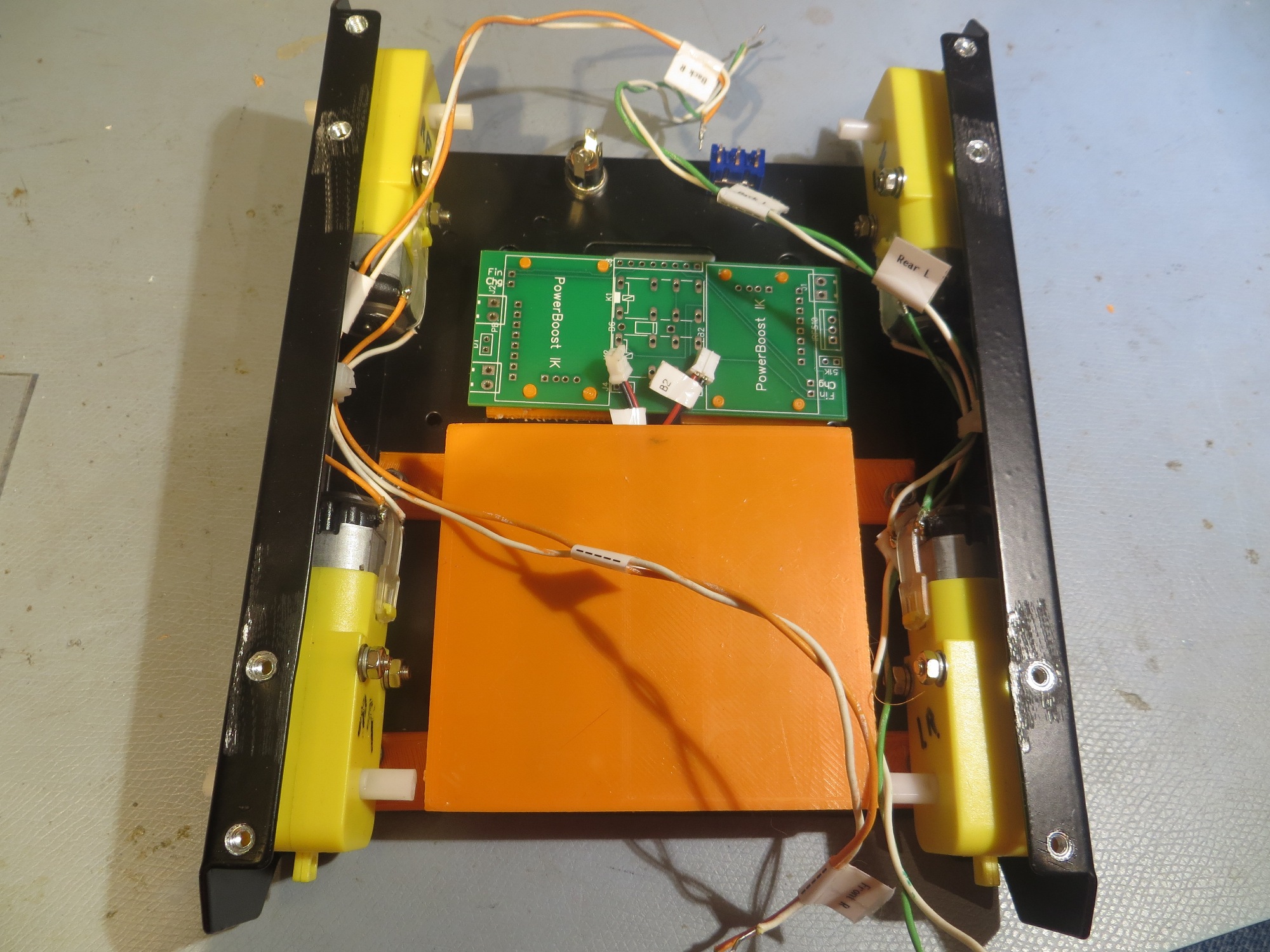
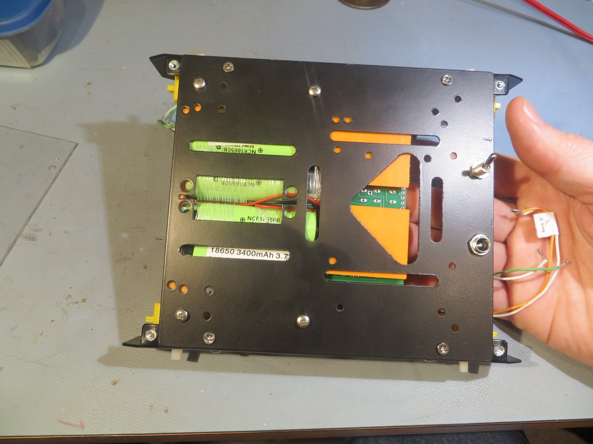
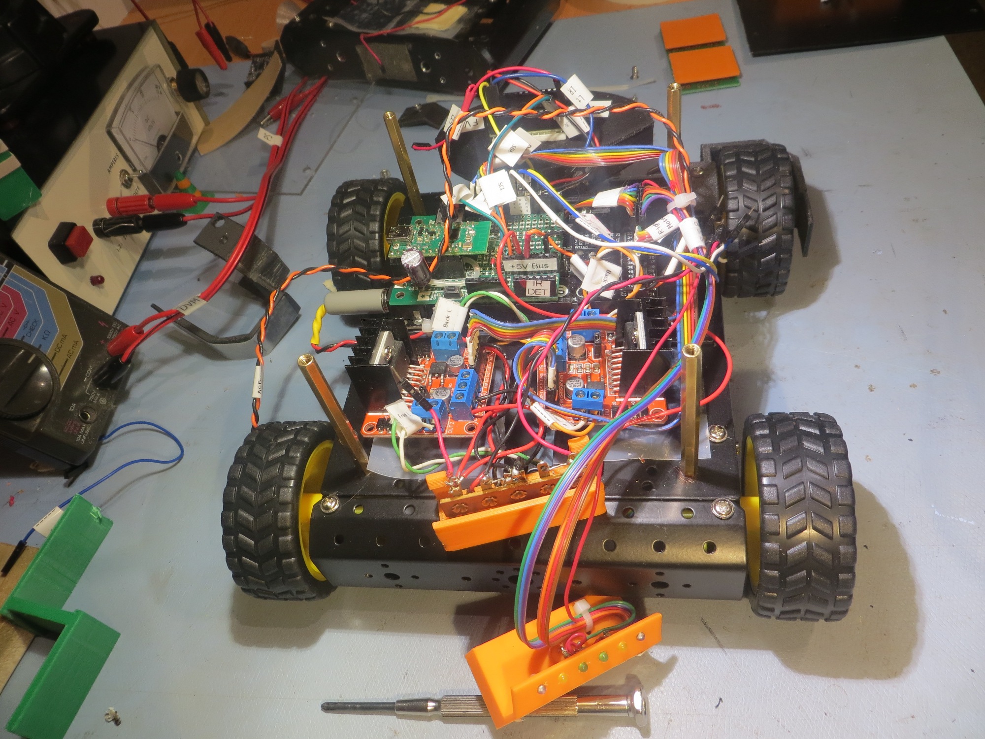
I’ve got almost everything transplanted over now, as shown in the following photos:

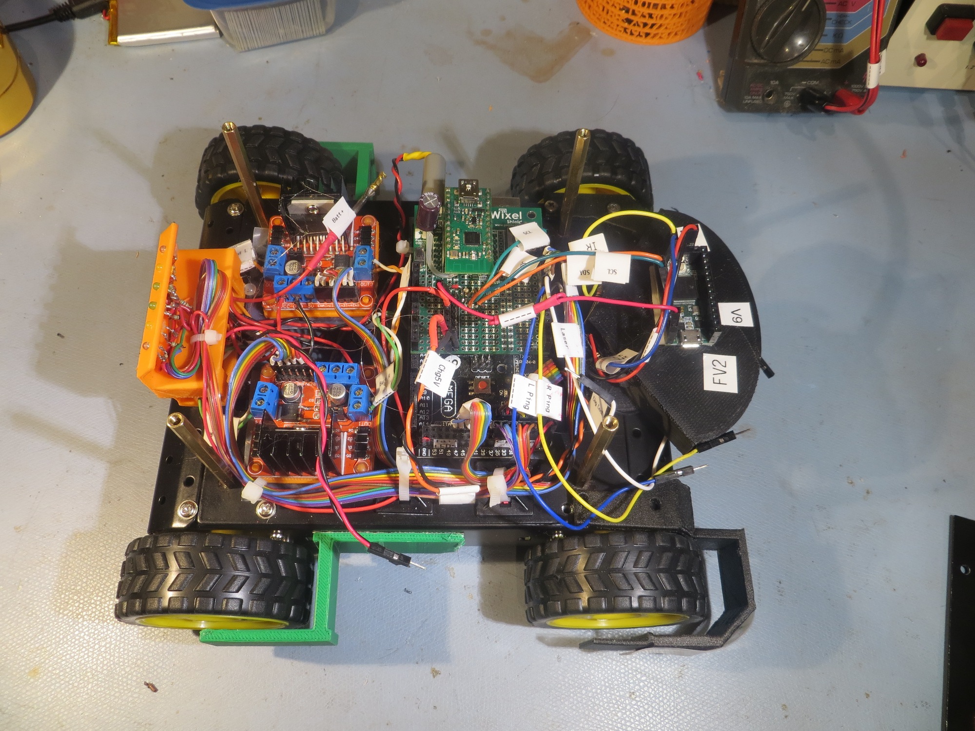
Side view without the sensor deck, showing that all modules are in place

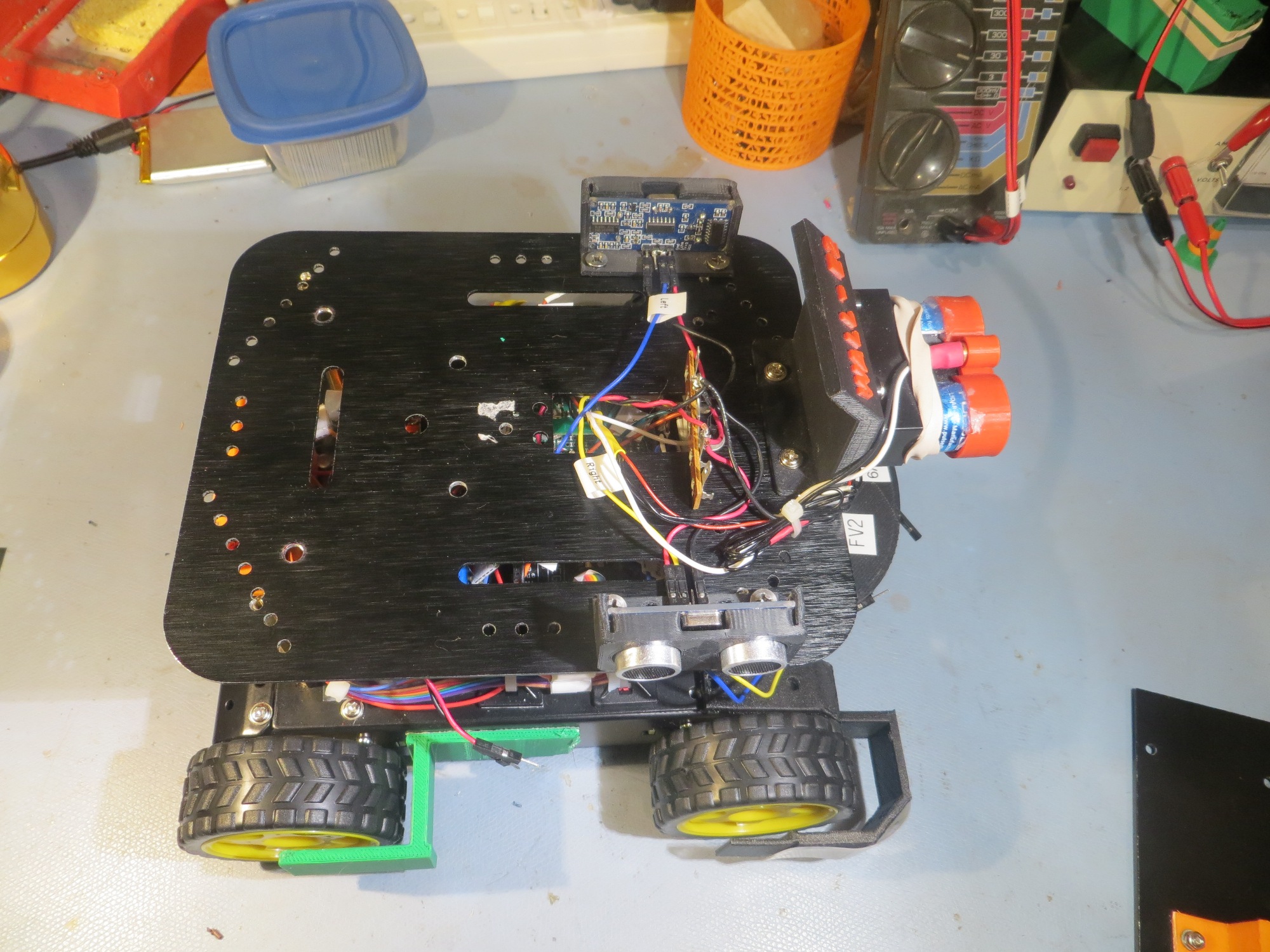
Side view showing the sensor deck in place.

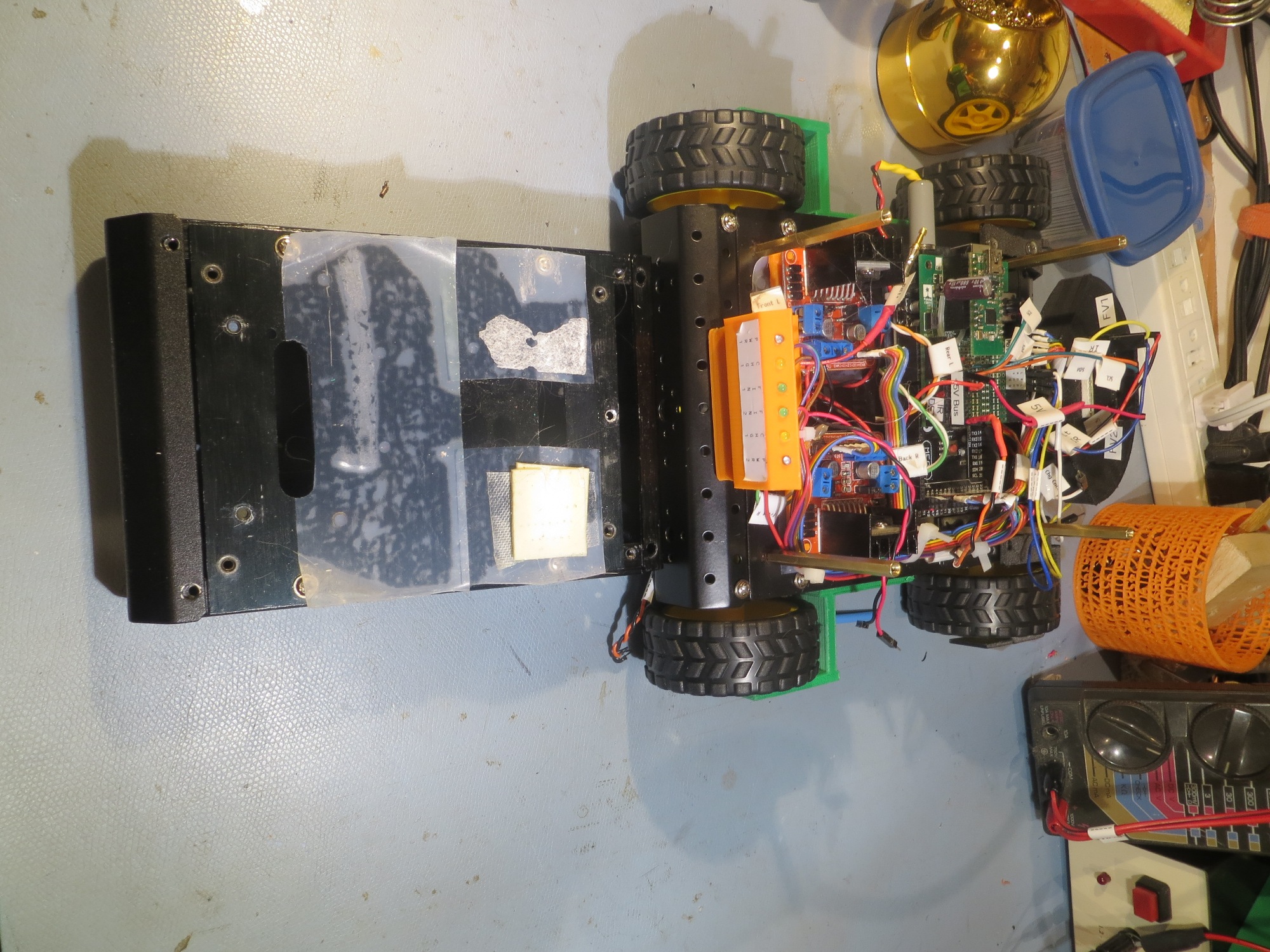
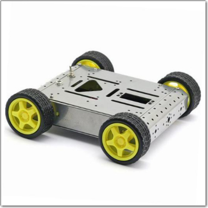
end-on view showing the difference between the old and new chassis dimensions

There’s still a ton of work to be done; The latest version of the charger PCB still hasn’t arrived from Bay Area Circuits, so I still need to do all that, and then wire the finished module into the battery compartment. Also, I’m having to redo the front bumper guards, as I have found they are somewhat fragile due to the way in which they were printed – bummer!   However, it shouldn’t be  too long before I can take the new model out for a spin! ;-).

Stay tuned!

Frank


A New Chassis For Wall-E2, Part I

Posted 06 November 2017

Back in May of this year I came to the conclusion that I was never going to get my new four-cell battery pack (4ea 18650 3600mAH 3.7V LiPo cells connected as 2ea 7400mAH 3.7V stacks) and its companion charger module to comfortably fit into Wall-E2’s current chassis.   It all fits, but only with a considerable amount of pushing and shoving which has invariably resulted in damage to something – a connector, a wire, or something else vital.

Bottom side view of 4WD robot showing battery packs and charging module

Bottom rear view of 4WD robot showing battery packs and charging module

So, I spent some quality time online looking for a new, larger home for Wall-E2, and found this chassis

Lightweight 4WD Drive Aluminum Mobile Dolly Car Robot Platform for Arduino

This chassis has an internal cavity width of about 14cm compared to 10.5cm for Wall-E2’s current ride.   This extra inch or so make all the difference in the world for comfortable installation of the battery pack and charger.

After getting this chassis on order, I basically forgot about it while I was working on the square-wave modulated IR homing project.   Then when my grandson Danny and his family visited in August, we dug out the kit and assembled it.   Danny wasn’t all that impressed with the quality (well, neither was I, but I didn’t expect all that much for $30 either).   After looking at both chassis (Wall-E2’s current ride and the new one), Danny suggested that maybe we could transplant the motors from the new chassis into the old one and get enough additional space from the different form factors to solve the battery problem.   At the time I pooh-poohed the idea, and put the new chassis back on the shelf to be forgotten again.

However, after finishing up the IR homing project last month, I decided I would actually try this trick and see what happened.   So, I laboriously swapped all four right-angle motors from the new chassis to the old one, and … RATS!!   As the photos below show, no real change in the available room for the charger/battery pack combination.   Well, at least I tried ;-).

So, now I’m back to swapping chassis (wow – plural form of ‘chassis’ is ‘chassis’ – go figure) instead of motors.

One of the major shortcomings in the new model was the cheapness of the threaded holes in the frame components.   The frame metal is so thin that instead of drilling and tapping the material, the holes were punched in a way that left the punched-out metal in the hole, and this material was tapped with the machine thread.   Needless to say, this lasted for about one (or fewer) screw/unscrew cycle before stripping out – bad design!.   Fortunately I knew how to fix this problem, with the help of McMaster-Carr.   I went to their site and ordered a bunch of press-fit nuts (also called PEM-nuts for historical reasons)

Press-fit nuts for my new robot chassis

In case you have never dealt with McMaster-Carr, they are incredibly quick.   I normally tell people that once I click on the ‘order’ button, I get up, walk to my front door, open it, and get hit in the chest by the shipped order! ;-).

Once I got the nuts, I replaced all the threaded holes on the new chassis with these wonderful little gadgets.   I used a #16 number drill to drill out the holes, and pressed the nuts in the new holes with a pair of cheap gas pliers – done!

As seen below, there is a  lot more room in the new model

In fact, there is so much room that now I have to figure out how to keep the batteries and charging module from sloshing around in there.   Fortunately I have a fertile imagination, TinkerCad, and a 3D printer – so I designed and printed up a battery box, and a prototype stand-off design for the PCB, as shown below.

The next part of the puzzle will be to figure out how all that stuff (IR Homing Module, laser and ultra-sonic distance sensors, motor controllers and the main controller) is going to fit on the new chassis.

Stay tuned!

Frank


Adafruit PowerBoost 1000C Charge Termination Threshold

Posted 01 November 2017

At the conclusion of my ‘field’ testing of Wall-E2’s new-found ability to mate with the charging station using the square-wave modulated beacon signal, I noticed that Wall-E2 was always disconnecting from the charging station based on elapsed time (set for 2Hrs at the moment) rather than detection of the end-of-charge condition.   After investigating this a bit more, I found that one of the charging modules never switched from charging to ‘finished’.   This was more than a little irritating, as I was counting on that transition to make sure that Wall-E2 was fully charged before disconnecting.

During the process of creating the PCB design for my charging module, I took a dive into the datasheet for the MCP73871 charge management chip on the PB1000C in an effort to figure out if there was any way to improve the end-of-charge detection situation.   When I looked through the specs (relevant data sheet portions shown below), I found that there is a spec called ‘Charge Termination Ratio’ (oddly shown with dimensions of mA, but what do I know), and this value is controlled by the value of the resistor connected to the PROG3 pin.

On the Adafruit PowerBoost 1000C module, the resistor attached to PROG3 is 100K, the larger of the two values mentioned in the datasheet, and this value sets the charge termination threshold at approximately 12.5 mA (according to the Adafruit gurus, ‘approximately here means +/- 25% – yikes!)

So, I decided to see if decreasing the value of this resistor give me a more robust charge termination experience.   Rather than trying to replace the SMT/SMD resistor part, I decided I could just mount a regular 1/8W resistor in parallel, with the value chosen to get the right resultant value.   Since there is such a large (+/- 25%) variation, there’s no real good reason for trying to arrive at an exact value, so I just chose a convenient value (meaning the closest value I could find in a small 1/8W package) – in this case, 51K.   With a little bit of patience, and a strong magnifier, I was able to get the resistor soldered onto the SMD part without burning up the pads or anything else, as shown in the following photo

51K resistor soldered in parallel with the existing 100K resistor on the MCP73871 PROGR3 pin

This parallel combination results in an PROG3 resistor value of about 33K, which (assuming a linear progression) should result in a charge termination current of about 40mA.   When I tried this setup with a mostly charged battery and an Adafruit ‘Charger Doctor’ for monitoring charge current, the PB1000C changed to the ‘finished’ state with a measured current of about 20mA.

When I first tried this trick, I was expecting the charge to terminate when the Charge Doctor readout showed “0.04” – but it didn’t happen until more like “0.02”.   When I mentioned this on the Adafruit forum, a very knowlegeable reply was forthcoming from “Mike”

Re: Powerboost 1000C Charge termination threshold

by  adafruit_support_mike  on Tue Oct 31, 2017 9:54 am

“Charge termination ratio” is a general term for LiPo chargers. Most of them don’t use an external resistor to set the cutoff current, and just end the charge cycle when the current flowing into the battery reaches a given fraction of the constant-current level.. 1% is fairly common.

If you run the math out, the ratio of I.prog:I.term is R.prog1:R.prog3

We started with 100k because that’s one of the two values listed in the DC Characteristics table, and after a while you learn to take datasheets very literally. They excel at telling you the parts of the truth the vendor wants you to hear, but nothing more. It’s always best to start from the exact spec values and then vary the parameters to see what they left out.

We left it at 100k because it worked, and the datasheets for the LiPos we carry spec 1% as the termination level.

The tolerance for that value is +/-25%, so a nominal value of 33mA can be expected to fall in the range between 24.75mA and 41.25mA. The Charge Doctor has a resolution of 10mV/10mA, and I’d expect its measurement error to be about half that through rounding if nothing else. That puts the potential range of measured values for a nominal 33mA current between 19.75mA (rounded to 20mA) and 46.25mA (rounded to 40mA).

The error is almost as large as the value you want to measure, and larger than the difference you want to measure.

 So I thought about that some more, and eventually realized that the cause of my non-termination woes might well be that I’m using these chargers on much larger (capacity-wise) cell stacks than normal.   I’m using a 7400 mA stack, so a 1% threshold would be 7.4mA, which may be a little too close for comfort to the 12.5 mA termination spec for a 100K resistor on PROG3.
In any case, this exercise taught me a  lot more about the PowerBoost 1000C in general, and the MCP73871 chip specifically.
Stay tuned,
Frank