Posted 09 October 2017
In my last post on this subject, I showed that the azimuth response from the V9 ‘crushed funnel’ sunshade design was almost ideal for the intended homing operation, and it was time to start seriously integrating it onto Wall-E2. As the following photos show, this worked out fairly well.
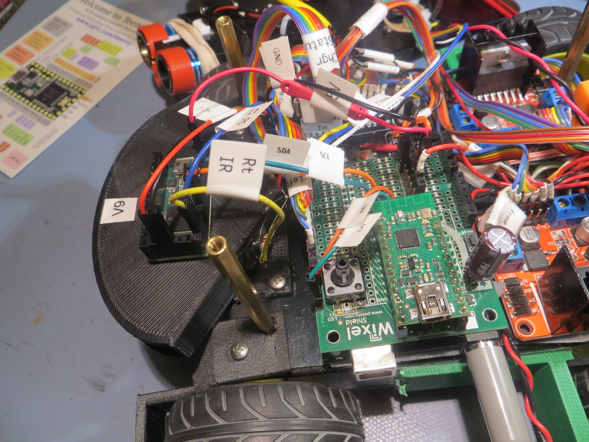
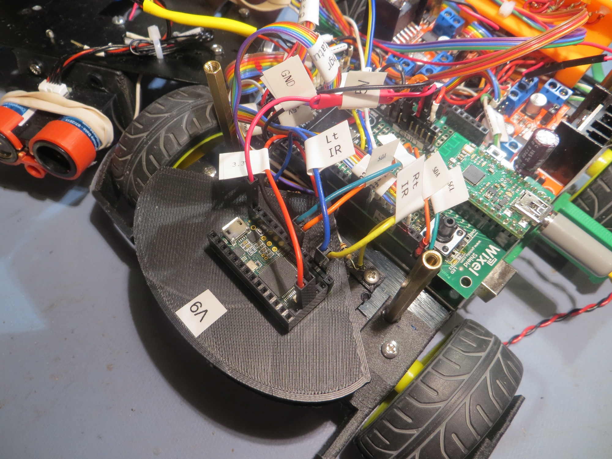
As shown in the above photos, the Teensy 3.2 IR Homing Module is mounted on the sunshade, with connections to the sunshade IR phototransister outputs on one end, and connections via I2C to the Mega on the other.
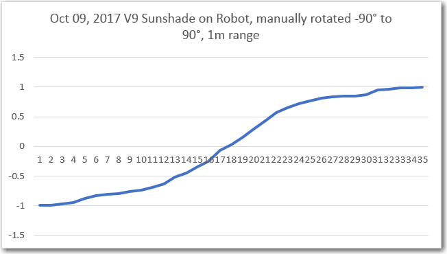
After making the necessary modifications to Wall-E2’s operating system to incorporate the steering value input from the homing module, I ran a short azimuth scan at 1m range using the completed IR Flashlight-based transmit module, as shown in the following short video.
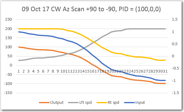
During the azimuth scan, steering values were acquired by the IR Homing module and transferred via I2C to the Mega on an as-requested basis. These values were then printed out to a PC using a Wixel wireless serial link. The result, as shown below, looks pretty good. It was pretty clear that the azimuth response was excellent over almost the entire azimuth range from -90 º to +90 º
The next step is to modify the PID parameters to translate the -1 to +1 range of steering values to appropriate wheel motor speed variations.
So, the error term varies from -1 to +1, and the motor wheel speed range is from 0-255, or MOTOR_SPEED_HALF +/- 127. So, I would expect to have to have a Kp value on the order of 100 or so to achieve the full range of motor speeds. I ran some manual scans for different Kp values to see what would happen with motor speeds, and got the following plots:
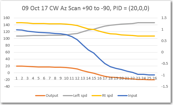
As expected, a Kp value of 20 appears to be a bit weak; it would do the job eventually, but probably not fast enough to get captured by the lead-in rails.
A Kp value of 100 looks better – motor speeds vary over almost the full range, so a full off-axis detection should cause Wall-E2 to almost spin in place to turn toward the beacon.
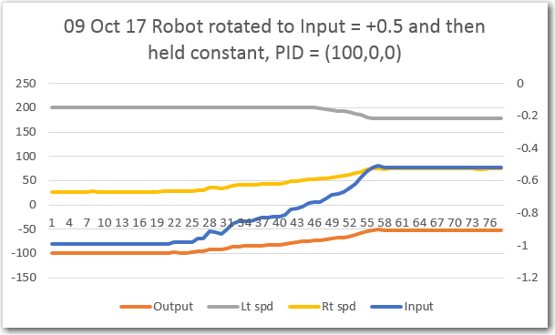
As shown above, using just Kp with Kd = Ki = 0 results in a constant offset with a constant error term. However, for this application a constant output will still result in the robot turning toward the beacon, so a constant offset shouldn’t be a problem.
After this last test, I noticed that an offset to the right of the beacon boresight line (as was the case for this test produced a high left wheel speed and a low right wheel speed, exactly the opposite of what would be required to reduce the error term – oops! This means I need to change the PID direction parameter from REVERSE to DIRECT to get the correct wheel speed adjustment sense.
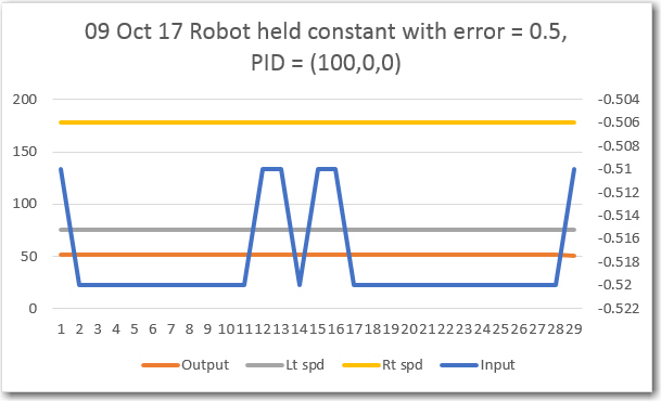
To produce the above plot, the robot was left in the same position as it was at the end of the last run – offset about 20-30 º to the right of the beacon boresight, but with the PID sense changed from REVERSE to DIRECT. As shown above, now the right motor speed is higher than the left, which would turn the robot back toward the beacon boresight.
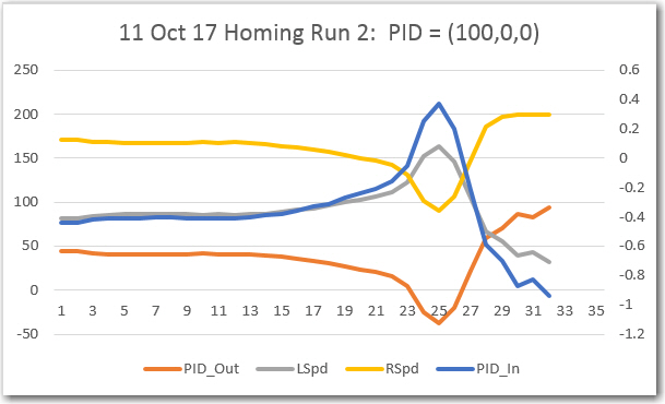
The data for all the above plots was collected with the wheel motors disabled. The next step will be to enable the motors and see what happens. I re-enabled the motors, but also implemented a wireless ‘kill switch’ so I could keep Wall-E2 from disappearing over the horizon (or more likely, over the edge of the bench!). Here’s Wall-E2’s maiden run with PID = (100,0,0)
Well, Wall-E2 didn’t home properly to the beacon, but it did manage to correct at least a little bit, and managed to not leap off the edge of my test bench – yay! The plot below shows the data from the run
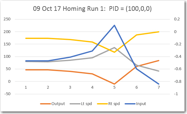
From the above plot, it is clear that Wall-E2 was trying to do the right thing, but couldn’t change the wheel speeds fast enough for effective homing. The input value started off at about -0.5, and the wheel speeds at L = 75, R = 175, which caused Wall-E2 to correct left, as it should. This started the input trending upwards toward zero, and the wheel speeds both tending toward 127 (i.e. half-speed). Everything arrived at the setpoint at position 5, so Wall-E2 continued straight, which took it back off the boresight and to the right side again. The input started down again, and the motor speeds started adjusting, but they couldn’t adjust fast enough to keep Wall-E2 from blowing past the beacon – oops!
I’m not real sure what this tells me about PID tuning, but I suspect I’m going to need a non-zero differential term to deal with the close-in rapid angle changes. It’s late, so I’m going to quit for tonight, but I hope to run some more tests tomorrow.
11 October Testing:
Here’s another run on my 1m test range (aka test bench). The only change from the previous run is that the data is being acquired at four times the rate – at 100mSec intervals vice 400mSec
The two plots shown above are almost identical, as would be expected, but the second plot has 4x the data points and is a lot smoother. Still, it tells the same story; the PID_In line (blue, plotted on the right-hand scale) stays relatively constant at about -0.5 until about position 13. With PID_In at -0.5, PID_Out (orange curve) is about 50, resulting in L/R speeds of about 75 & 175 (grey & yellow curves, resp). These speeds cause a very gentle turn to the left (way too gentle, as it turns out). After position 13, PID_In starts rising slowly (and then more rapidly) toward zero, indicating that the robot heading is nearing the beacon boresight. At position 23 PID_In hits -0.1 and the wheel speeds cross at a value of 125, meaning the robot is moving more or less straight ahead. For some currently unknown reason, PID_In actually goes significantly above zero between positions 23 and 25, causing the robot to ‘twitch’ to the right, away from the beacon! Then at position 25 PID_In reverses course, diving from +0.3 to -1 as the robot goes past the beacon. This causes the robot to reverse course again, undoing the ‘twitch’ just before hitting the end-of-range condition (aka my tool chest).
So, why did PID_In (i.e. the steering value coming from the IR Homing Module) continue to increase even as the angle between the beacon boresight and the robot centerline continued to increase – not decrease?
More 11 October Testing:
Rather than worry about the ‘twitch’ phenomenon observed just before Wall-E2 passed the IR beacon, I decided to attack the first part of the run, where the PID input stayed relatively constant, but well offset from the setpoint. From my reading of PID tuning, this indicates a need for a non-zero I (integration) term. To test this, I adjusted my PID value from (100,0,0) to (100, 20, 0) and ran some more testing. The 1m range runs were encouraging, so I tried a run on my 2m range (aka my lab floor). As the following video and accompanying data plots show, this was pretty darned successful.
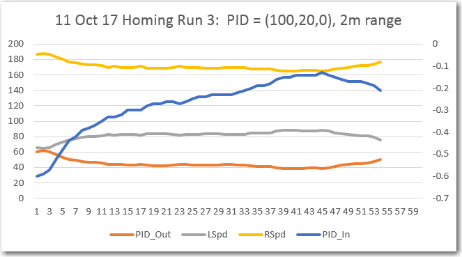
Starting at an offset angle of about 30-40 º relative to beacon boresight, Wall-E2 homed in on the beacon very smoothly and accurately. In fact, when I picked up Wall-E2, I found that it had partially mated with the charging probe, even without lead-in rails for physical registration – neat!
Here’s another run, with Wall-E2 starting from the other side, with more of an initial offset (almost 90 º)
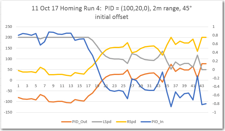
As can be seen in the above video clip and accompanying plot, Wall-E2 makes an abrupt initial turn to point (generally) toward the beacon, but then doesn’t make any additional significant corrections until it is almost past the beacon. From the plot, it appears that the I value isn’t quite high enough. So, I plan to make some more runs with increased I values.
Stay tuned!
Frank