Monthly Archives: October 2017

Wall-E2 Battery Charger PCB Part I

Posted 18 October 2017

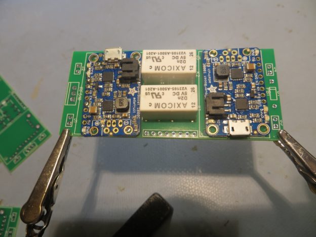
Wall-E2’s on-board battery system has gone through some major changes over the last three years or so. Back in October 2015 I implemented an on-board battery pack & charger using two Sparkfun boost chargers and two 2000 mAh LiPo batteries as shown in the following image.


Battery pack showing charging modules and switching relay. The tan capacitor-looking component is actually a re-settable fuse

This was a technical success, but a practical failure; the LiPo cells just didn’t have the oomph to handle the high motor currents, and the single relay design had some problems as well.    So, in December 2015 I replaced the entire on-board battery system with a much higher discharge capacity RC battery, the GForce 2200 battery pack, as shown below

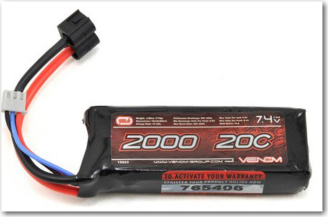
Current Wall-E2 battery pack

However, using this battery required that I physically disconnect the battery and connect it to an off-board charger for recharges, which meant I could never implement my idea of an autonomous robot.

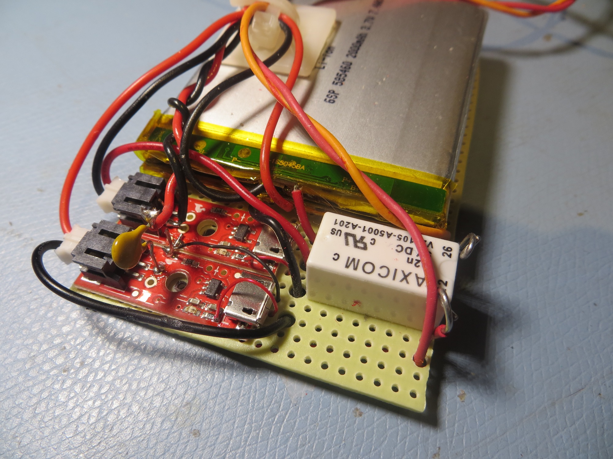
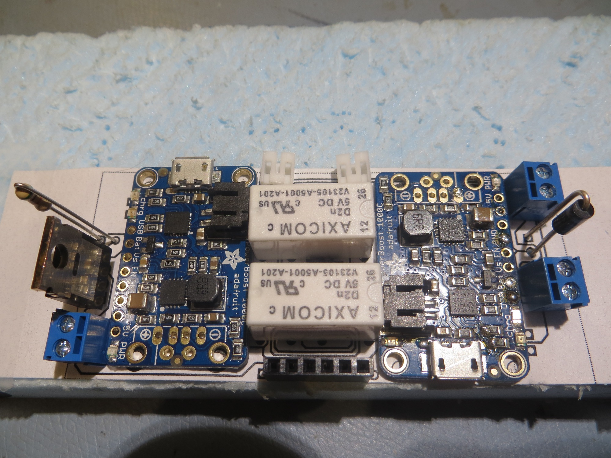
So, about a year ago,  I re-implemented the on-board charging system, but with two significant changes; I used two 2-cell stacks of 3700 mAh 18650-style 3.7V li-ion batteries (specifically the NCR18650B cell) instead of the 2000 mA LiPo flatpacks, and two Adafruit PowerBoost 1000C chargers instead of the Sparkfun units.   I also added a second Axicom DPDT relay to solve the previous overvoltage issue.   The result is shown in the photograph below

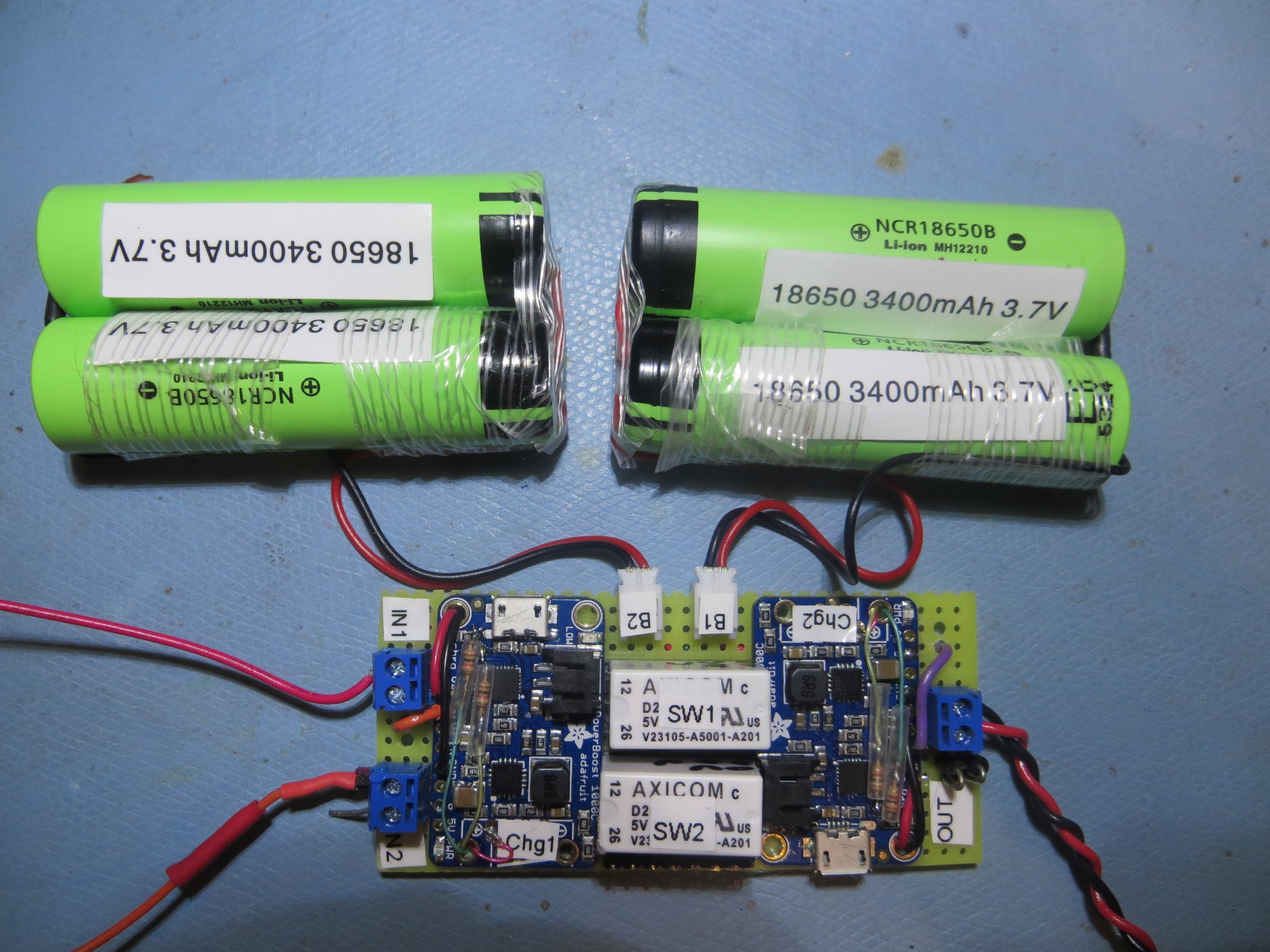
Finished charging module connected to two 2-cell 3.7V battery packs

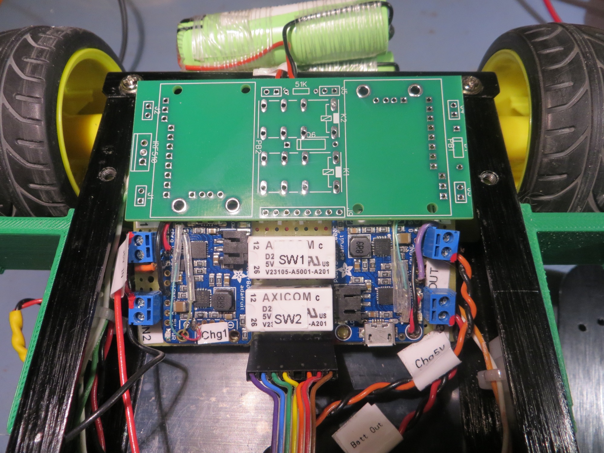
This system worked very well, and with the modifications  discussed in this post from last January (January 2017), I had a complete system for autonomous on-board charging.

This system has worked extremely well, but now I wanted to duplicate it for a planned upgrade to a larger robot platform, and I really wasn’t looking forward to hand-wiring another board. What I needed was a PCB, so I (or anyone else) could fabricate any number of charging modules without the PITA factor of a hand-wired perf-board implementation, so I decided to see If I could make a PCB using the free version of DipTrace.

After fumbling around for a while in DipTrace, I soon realized that in order to do a good job with a PCB design, I needed a component and associated PCB pattern for the Adafruit PowerBoost 1000C, and AFACT, none existed – at least not in a form compatible with DipTrace.   So, after some more fumbling around, I came up with the following model for the PB1K

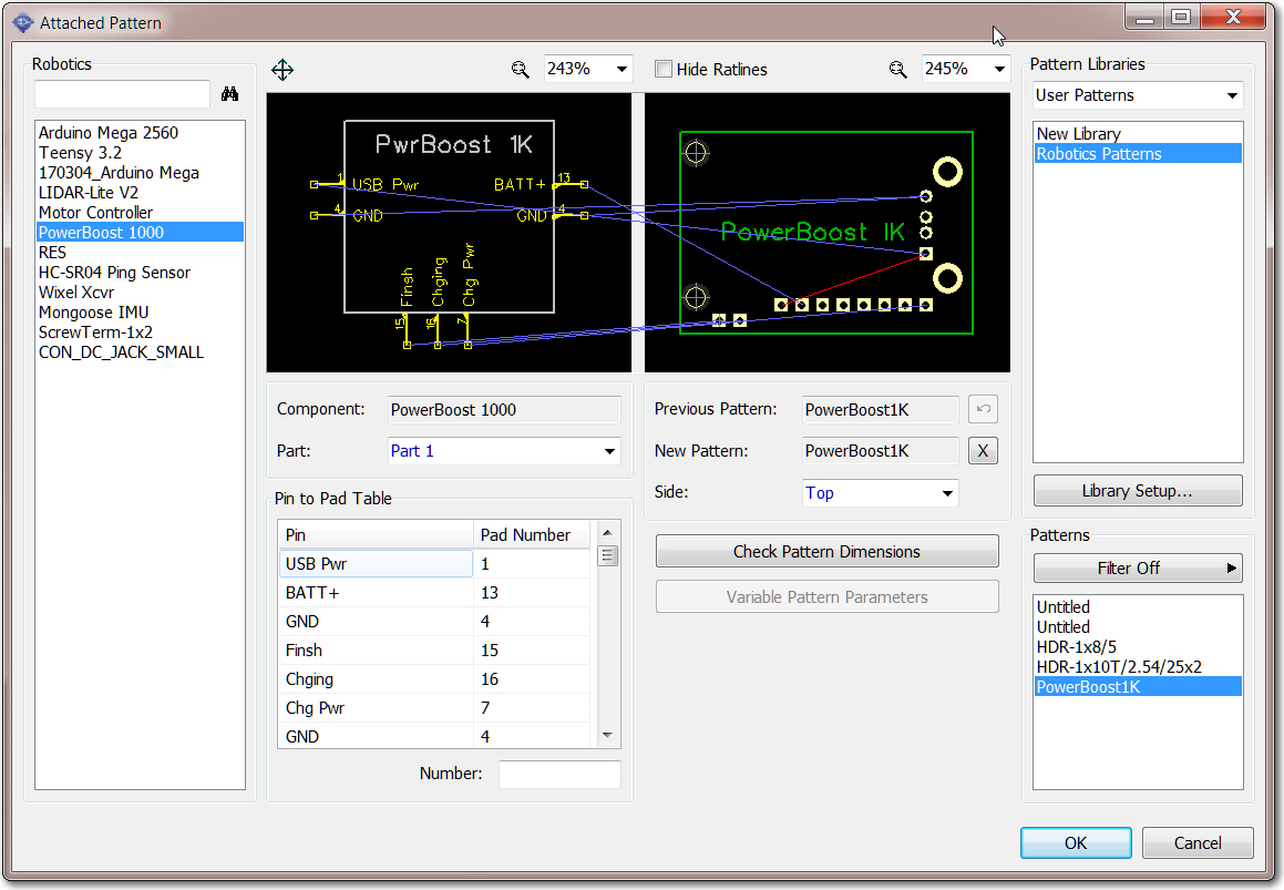
DipTrace component model for the Adafruit PowerBoost 1000C

Creation of this component was complicated by the fact that I needed ‘flying lead’ connections to the ‘charging’ and ‘finished’ LED drivers on the PB1K module – signals that aren’t exposed to the outside world.   Eventually I hit upon the idea of adding a couple of ‘off-board’ pads (shown above at the lower left corner of the pattern), and assigning them to the ‘Finish’ and ‘Charging’ functions of the component layout. The ‘Chg Pwr’ signal already existed on the breakout header as the ‘Power’ signal, so I didn’t need anything for that.   These modifications allowed me to integrate the PB1K module into the charger schematic and the PCB layout using the normal DipTrace project work flow.

After getting what I thought was a successful layout, I clicked the ‘Order PCB’ button in the PCB editor, and ordered their minimum of two PCBs for $30 + shipping (I actually received 4ea PCBs so it was an even greater deal than normal!).

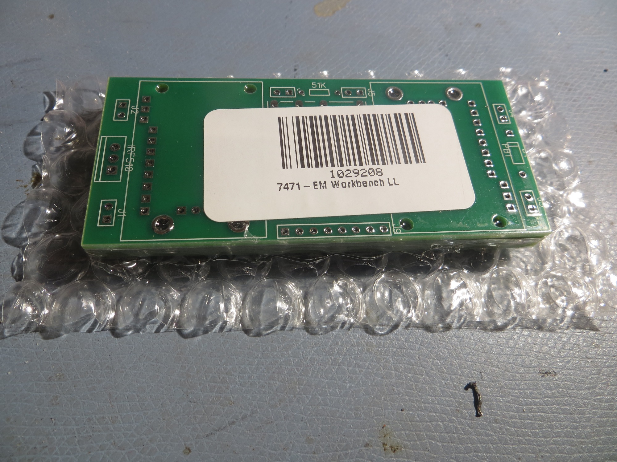
PCBs as received from Bay Area Circuits – nice packaging!

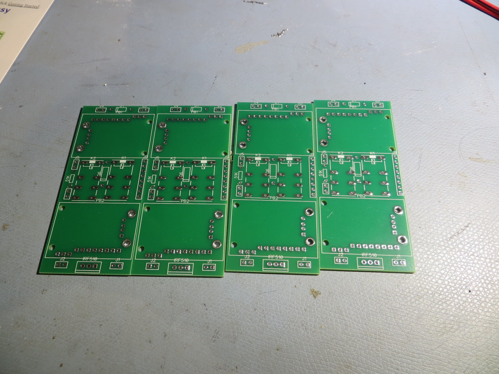
Four PCBs for the price of two – cool!

Test run to populate PCB with actual components

Size comparison between PCB and hand-wired versions. First iteration of PCB is slightly larger

After inspecting the PCBs, I realized I had screwed up on a couple of items.   The pad pattern for the two-wire terminal blocks wasn’t correct (too small), and at least one of them was reversed – oops!   In addition, a couple of PCB traces weren’t correct. So, it was back to the drawing board (literally) for a ‘version 2’ PCB.   On this iteration I learned a good bit more about DipTrace’s schematic/component/pattern relationship, so I felt like I was getting at least some value out of my screwups.   After removing a superfluous 2-wire terminal block and moving a couple of parts around, I was able to make the V2 PCB smaller than the original hand-wired model.   This time I remembered to use DipTrace’s verification routines, and this allowed me to catch some additional problems that had made it through into V2.   In addition, I used DipTrace’s print facility to print out a 1:1 PCB layout on paper, so I could double-check parts placement with real components, as shown in the following photo

Second iteration PCB printed at 1:1 scale on paper for component fit testing

So, many hours and a couple of iterations later, I have what I believe is a successful PCB implementation, and I sent off a new order to BAC.    As usual, I wound up spending  far more time designing the PCB than I ever would have in making a second hand-wired unit for the new robot, but where’s the fun in  that?

Stay tuned

Frank


IR Homing Module Integration Part X

Posted 15 October 2017

Well, we have just about reached the end of the road with respect to the ‘IR Homing Module Integration’ adventure.   As you may recall, at the very start of this trip (a couple of centuries ago back in August of this year) I showed the following block diagram of the proposed integration architecture

Teensy 3.2-based IR Demod module block diagram

The above architecture actually worked almost exactly as planned, except for using only two phototransistors vs the four in the original design, as shown below

Revised IR Demodulator block diagram. Note the removal of two phototransistors and the input combiner

After literally dozens of trials on my 1m (aka workbench) and 2m  ranges (aka the floor of my lab), I believe I have arrived at a reasonably successful set of PID parameters for Wall-E2 to use when homing to a charging station.   As usual, after going all around the barn with different P, I, & D values, I wound up with the simplest possible set of parameters, namely PID = (200,0,0).   The ‘200’ value is due to the use of a   (L-R)/(L+R) computation in the IR homing module, resulting in a steering   value output that ranges from -1 to +1.

While the result at the moment is far from perfect, it  is pretty good.   Wall-E2 can now successfully home to and mate with the charging station from at least 3m away, with wall offset distances from 50-91 cm as shown in the following videos (as can be seen in the last video, there is still some work to be done for wall offsets in the 25cm range)


So, the IR Homing Module Integration project is basically complete.   To recap, the idea for an interference-resistant IR homing scheme using a square-wave modulated IR beacon and a companion ‘degenerate N-path Band-pass Filter’ demodulator started back in May of this year during a visit from my old friend and mentor John Jenkins (see this post).   Since then, Wall-E2 and I have done the following:

  • Researched the basic theory behind the ‘N-path band-pass filter’ technology
  • Designed and implemented (with John’s help) a two-channel version of the technique using an arduino Uno.
  • When the Uno turned out to be too slow for operation at the desired 520Hz square-wave frequency, reduced the operating frequency by a factor of 10 to 52Hz to verify proper operation
  • Researched faster alternatives to the Uno, and eventually settled on the Teensy 3.x line of micro-controllers.   This hardware change allowed me to run the algorithm successfully at 520Hz, while simultaneously cutting the required real-estate by a factor of four, and the current drain by a factor of two – neat!
  • Designed and implemented the ‘crushed funnel’ two-phototransistor detector sunshade.
  • Integrated everything onto the Wall-E2 robot.
  • Demonstrated successful homing in the presence of overhead halogen lighting

Remaining Work:

There are still some things that need to be cleaned up to complete the integration, but it is mostly minor stuff:

  • I’m still not entirely happy with the inability to successfully home & mate with the charger for wall-following offsets below about 25cm, but I don’t think there is anything I can do realistically to solve that problem; what I  can do, however, is to make sure Wall-E2 starts homing far enough away from the nearest wall to avoid that problem. This will probably mean something like a pre-homing maneuver if the nearest wall distance is too small (or maybe even changing the basic wall-following algorithm to maintain a minimum distance of > 25cm)
  • Along the lines of belt-and-suspender designs, I probably also need to implement some sort of fallback algorithm if, despite all my best efforts, Wall-E2  still  manages to impale itself on one of the lead-in rails.   When Wall-E2 is in normal wall-following mode and gets stuck, it has a way of detecting that condition and recovering, but that scheme isn’t currently active during homing operations.   I just need to copy that capability into the homing mode, and hopefully Wall-E2 will cooperate.
  • There’s a whole bunch of commented-out stuff and debugging printout code scattered through the program right now, and that stuff needs to be cleaned out before I forget (if I haven’t already) what it was originally intended to do.

In any case, it is time to declare victory move on to the next challenge, as soon as I figure out what that might be.

Stay tuned!

Frank


IR Homing Module Integration Part IX

Posted 09 October 2017

In my last post on this subject, I showed that the azimuth response from the V9 ‘crushed funnel’ sunshade design was almost ideal for the intended homing operation, and it was time to start seriously integrating it onto Wall-E2.   As the following photos show, this worked out fairly well.

As shown in the above photos, the Teensy 3.2 IR Homing Module is mounted on the sunshade, with connections to the sunshade IR phototransister outputs on one end, and connections via I2C to the Mega on the other.

After making the necessary modifications to Wall-E2’s operating system to incorporate the steering value input from the homing module, I ran a short azimuth scan at 1m range using the completed IR Flashlight-based transmit module, as shown in the following short video.

During the azimuth scan, steering values were acquired by the IR Homing module and transferred via I2C to the Mega on an as-requested basis.   These values were then printed out to a PC using a Wixel wireless serial link.   The result, as shown below, looks pretty good.  It was pretty clear that the azimuth response was excellent over almost the entire azimuth range from -90 º to +90 º


The next step is to modify the PID parameters to translate the -1 to +1 range of steering values to appropriate wheel motor speed variations.

So, the error term varies from -1 to +1, and the motor wheel speed range is from 0-255, or MOTOR_SPEED_HALF +/- 127.   So, I would expect to have to have a Kp value on the order of 100 or so to achieve the full range of motor speeds.   I ran some manual scans for different Kp values to see what would happen with motor speeds, and got the following plots:

As expected, a Kp value of 20 appears to be a bit weak; it would do the job eventually, but probably not fast enough to get captured by the lead-in rails.

A Kp value of 100 looks better – motor speeds vary over almost the full range, so a full off-axis detection should cause Wall-E2 to almost spin in place to turn toward the beacon.


As shown above, using just Kp with Kd = Ki = 0 results in a constant offset with a constant error term.   However, for this application a constant output will still result in the robot turning toward the beacon, so a constant offset shouldn’t be a problem.

After this last test, I noticed that an offset to the right of the beacon boresight line (as was the case for this test produced a high left wheel speed and a low right wheel speed, exactly the opposite of what would be required to reduce the error term – oops!   This means I need to change the PID direction parameter from REVERSE to DIRECT to get the correct wheel speed adjustment sense.

To produce the above plot, the robot was left in the same position as it was at the end of the last run – offset about 20-30 º to the right of the beacon boresight, but with the PID sense changed from REVERSE to DIRECT. As shown above, now the right motor speed is higher than the left, which would turn the robot back toward the beacon boresight.

The data for all the above plots was collected with the wheel motors disabled.   The next step will be to enable the motors and see what happens.   I re-enabled the motors, but also implemented a wireless ‘kill switch’ so I could keep Wall-E2 from disappearing over the horizon (or more likely, over the edge of the bench!).   Here’s Wall-E2’s maiden run with PID = (100,0,0)


Well, Wall-E2 didn’t home properly to the beacon, but it did manage to correct at least a little bit, and managed to not leap off the edge of my test bench – yay!   The plot below shows the data from the run

From the above plot, it is clear that Wall-E2 was trying to do the right thing, but couldn’t change the wheel speeds fast enough for effective homing.   The input value started off at about -0.5, and the wheel speeds at L = 75, R = 175, which caused Wall-E2 to correct left, as it should.   This started the input trending upwards toward zero, and the wheel speeds both tending toward 127 (i.e. half-speed).   Everything arrived at the setpoint at position 5, so Wall-E2 continued straight, which took it back off the boresight and to the right side again.   The input started down again, and the motor speeds started adjusting, but they couldn’t adjust fast enough to keep Wall-E2 from blowing past the beacon – oops!

I’m not real sure what this tells me about PID tuning, but I suspect I’m going to need a non-zero differential term to deal with the close-in rapid angle changes.   It’s late, so I’m going to quit for tonight, but I hope to run some more tests tomorrow.

11 October Testing:

Here’s another run on my 1m test range (aka test bench). The only change from the previous run is that the data is being acquired at four times the rate – at 100mSec intervals vice 400mSec

The two plots shown above are almost identical, as would be expected, but the second plot has 4x the data points and is a lot smoother.   Still, it tells the same story; the PID_In line (blue, plotted on the right-hand scale) stays relatively constant at about -0.5 until about position 13.   With PID_In at -0.5, PID_Out (orange curve) is about 50, resulting in L/R speeds of about 75 & 175 (grey & yellow curves, resp).   These speeds cause a very gentle turn to the left (way too gentle, as it turns out).   After position 13, PID_In starts rising slowly (and then more rapidly) toward zero, indicating that the robot heading is nearing the beacon boresight.   At position 23   PID_In   hits -0.1 and the wheel speeds cross at a value of 125, meaning the robot is moving more or less straight ahead.   For some currently unknown reason, PID_In actually goes significantly above zero between positions 23 and 25, causing the robot to ‘twitch’ to the right, away from the beacon!   Then at position 25 PID_In reverses course, diving from +0.3 to -1 as the robot goes past the beacon.   This causes the robot to reverse course again, undoing the ‘twitch’ just before hitting the end-of-range condition (aka my tool chest).

So, why did PID_In (i.e. the steering value coming from the IR Homing Module) continue to increase even as the angle between the beacon boresight and the robot centerline continued to increase – not decrease?

More 11 October Testing:

Rather than worry about the ‘twitch’ phenomenon observed just before Wall-E2 passed the IR beacon, I decided to attack the first part of the run, where the PID input stayed relatively constant, but well offset from the setpoint. From my reading of PID tuning, this indicates a need for a non-zero I (integration) term.   To test this, I adjusted my PID value from (100,0,0) to (100, 20, 0) and ran some more testing.   The 1m range runs were encouraging, so I tried a run on my 2m range (aka my lab floor). As the following video and accompanying data plots show, this was pretty darned successful.


Starting at an offset angle of about 30-40 º relative to beacon boresight, Wall-E2 homed in on the beacon very smoothly and accurately.   In fact, when I picked up Wall-E2, I found that it had partially mated with the charging probe, even without lead-in rails for physical registration – neat!

Here’s another run, with Wall-E2 starting from the other side, with more of an initial offset (almost 90 º)

As can be seen in the above video clip and accompanying plot, Wall-E2 makes an abrupt initial turn to point (generally) toward the beacon, but then doesn’t make any additional significant corrections until it is almost past the beacon.   From the plot, it appears that the I value isn’t quite high enough.   So, I plan to make some more runs with increased I values.


Stay tuned!

Frank