Posted 18 September 2017
So now that I have the Teensy 3.2-based IR Homing module working on the robot end, I shifted my attention to the charging station end. Now that I’m using a square-wave modulated IR beacon signal, I needed to separate the LED drive and charging probe circuits; the charging probe needs a constant +5VDC, but the LED circuit needs a pulsed signal.
So, I pulled an IRF-510 power MOSFET from my supplies and wired it up to switch about 200mA through the TSAL-6200 IR LED, driven from the output of my Teensy 3.2-based sweep generator. I needed to mount the Teensy and the IRF-510 on the charger/beacon module, so I used a 1950’s era terminal strip, some hot glue, and some double-sided foam tape – see the photo below.
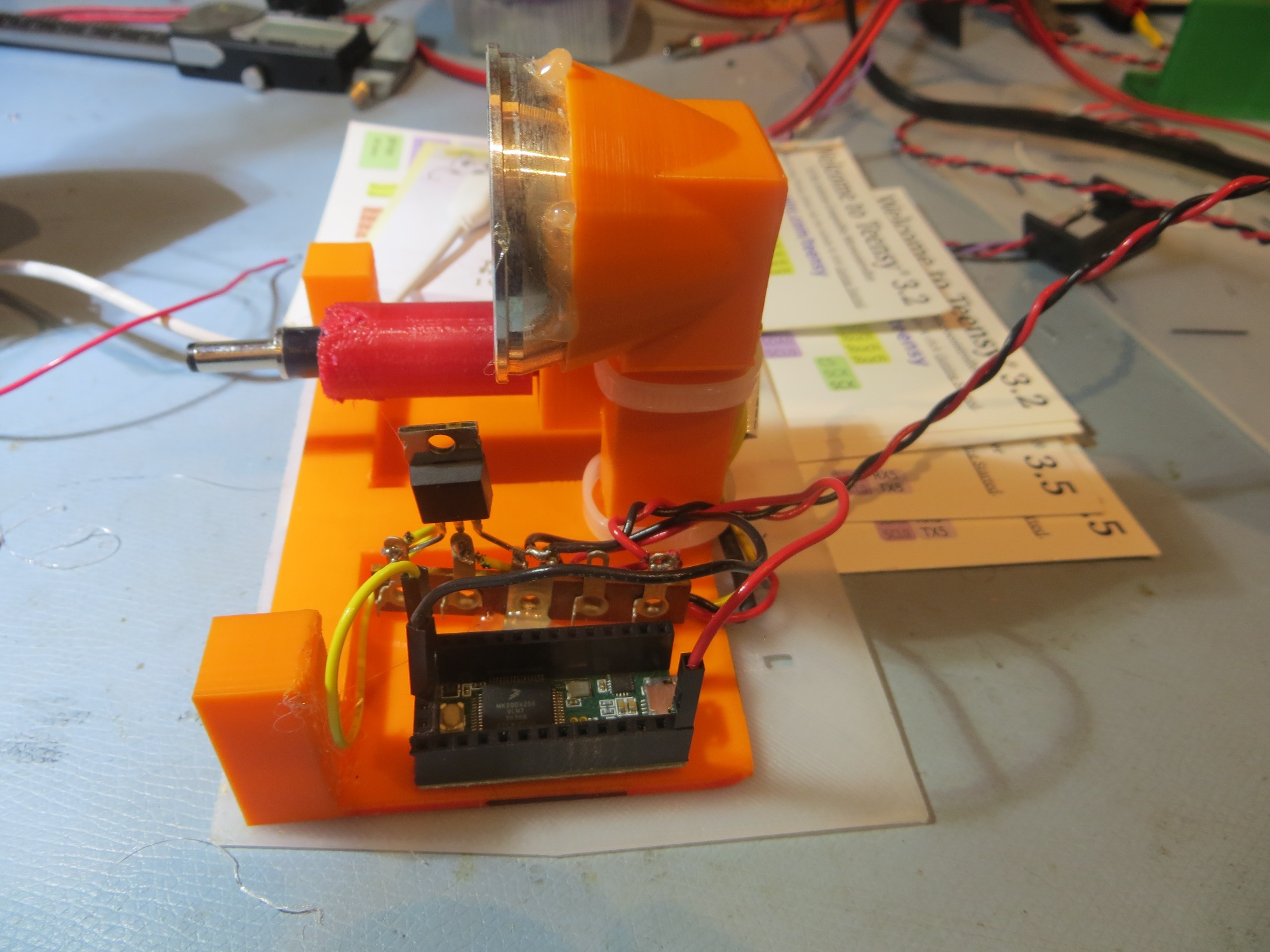
Teensy waveform generator and IRF-510 MOSFET mounted on charging station module
I used my CCD camera to verify that the TSAL-6200 IR LED was indeed LED-ing, as shown in the following photo
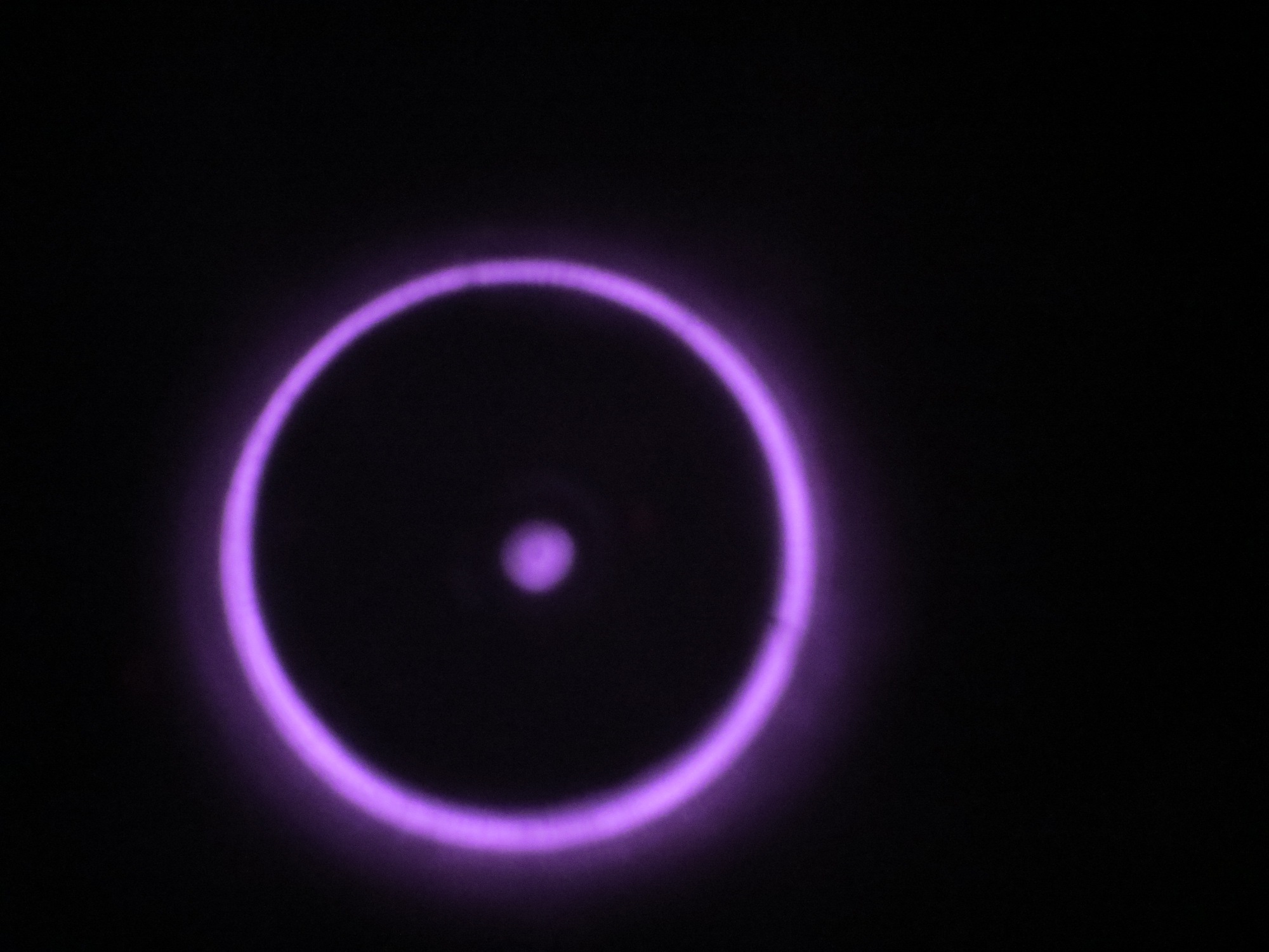
CCD camera shot of square-wave modulated IR beam from TSAL-6200 mounted in a flashlight reflector. Note the direct and reflected energy.
Then I used my Teensy-based rotary table controller and IR Beacon Homing Module to generate an azimuth scan, as shown below.
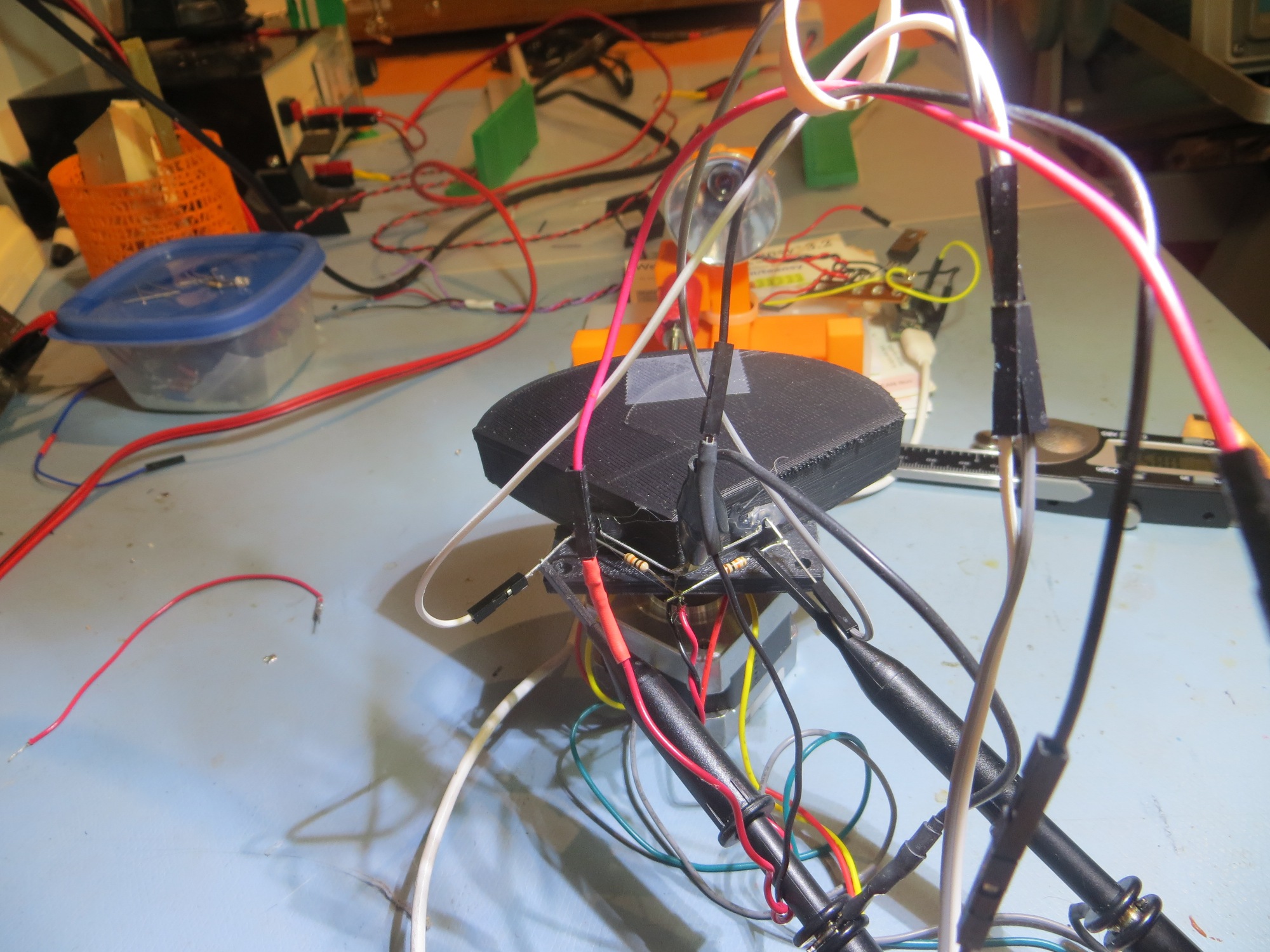
Setup for azimuth scan acquisition
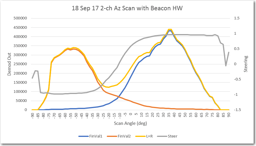
Azimuth scan using 2ea SFH-314 photo transistors
And here’s a scope photo showing the square-wave modulation waveform at the Charging Station Module and the received waveform at the IR Homing Module
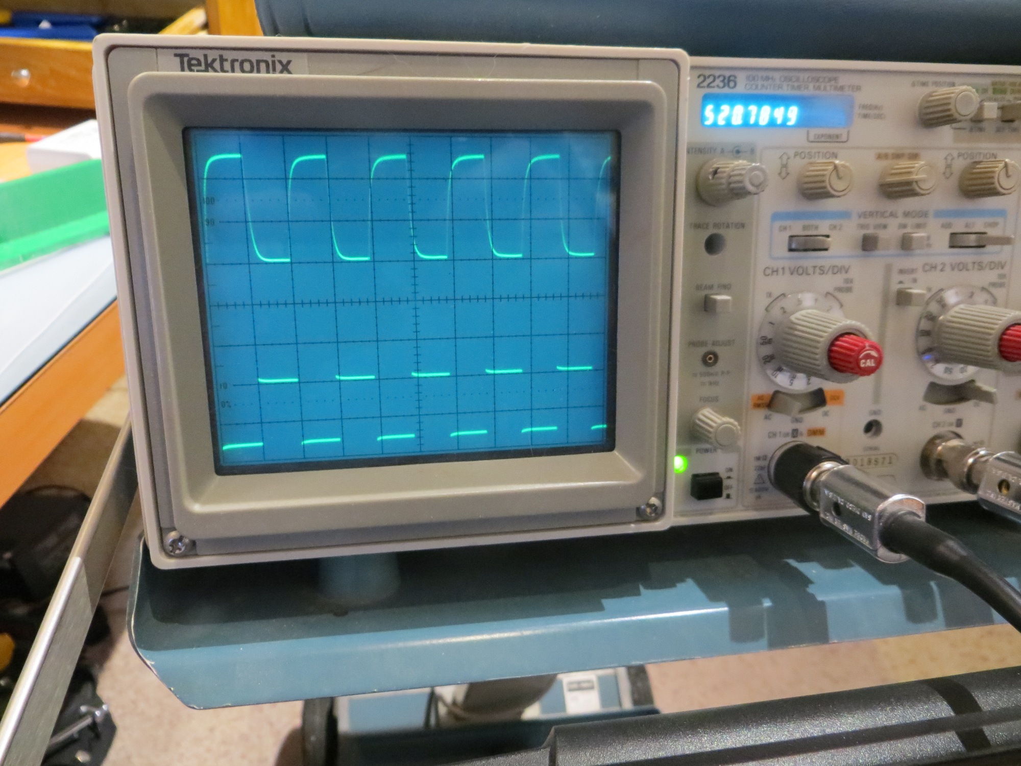
Square-wave transmit modulation (bottom trace) and received waveform at the IR Homing Module (upper trace)
So, at this point I have both the transmit and receive halves of the square-wave modulated beacon system working, but (as usual) there are still some significant flies in the ointment.
- I’m still worried about the ambient light interference issue, although my initial tests with the improved sunshade have been encouraging. With the setup as shown in the above scope photo, turning the overhead incandescent indoor spots on and off just caused a barely perceptible DC drop in the upper waveform.
- In the same vein, I’m concerned that the TSAL-6200 LED, even pulsed at 200mA, won’t give me the detection range I need for successful homing to the charging station capture basket, especially if I further reduce the phototransistor Rc values to make the system less susceptible to IR ‘flooding’.
- The azimuth scan data indicates that the SFH-314 phototransistors may not be optimally aligned. It looks like they should be oriented a little more parallel to each other to close the central response gap.
Stay tuned!
Frank
Why the lighted ring in LED-ing picture?
The lighted ring is actually from the LED after being reflected off the flashlight reflector. The ‘dot’ in the middle is the direct ray, and the ring is the reflected ray