Posted 21 September 2017
As I mentioned at the end of the previous post on this subject, there are still some ‘issues’ with the charging station system.
Ambient light flooding, TSAL-6200 LED Power:
AFAIK, there are only two ways to beat the ambient light flooding problem; by reducing the amount of ambient light allowed to hit the phototransistors, or reducing the gain of the phototransistors, or both. The ‘flat funnel’ sunshade design appears to be effective in reducing the incidence of ambient light from above (i.e. overhead incandescent lighting and sunlight) while preserving off-axis beacon detection ability, but it may not be enough by itself. The problem with reducing detector gain to a level that would guarantee protection from flooding is that it might make it impossible to detect the charging station signal from far enough (i.e. around 2m away) to maneuver in time to be captured by the charging station lead-in rails. Thus, the lower limit on the detector gain is set by the beacon field strength at approximately 2m distance. So, if I want to reduce the detector gain, I have to increase the IR beacon field strength.
With the current setup with a single-TSAL-6200 IR LED transmitter, there’s not much more I can do to increase field strength at 2m. The flashlight reflector idea significantly increased detection range, but even with the reflector I had to use a gain resistor of over 100K to achieve 2m detection/homing range, and that is probably 2 orders of magnitude greater than the maximum gain for flooding prevention. The use of a square-wave modulation with it’s 50% duty factor makes this situation even worse, although I can get most of this loss back by running the LED at 200mA instead of 100.
While I was pondering my navel on this subject, someone mentioned that there are now small, cheap IR flashlights available for the tactical and hunting markets, and these flashlights use one or more Cree high-power IR LEDs. I happened to be familiar with the Cree line of LEDs, as I have used their visual-light models to replace the el-cheapo LEDs in a couple of my bench lamps. The visual-light models can easily handle 1Amp, and at that current are too bright to look at directly. A little research showed that the IR models have the same high power rating, making them ideal for this purpose. In addition to the high power, the IR flashlights typically come with adjustable optics that allow for a broad or spot beam, which would eliminate the requirement for a reflector – cool!
So, I ordered a ‘IR-940’ IR flashlight from eBay, and it looks like it might fill the bill. The flashlight as received is shown below.
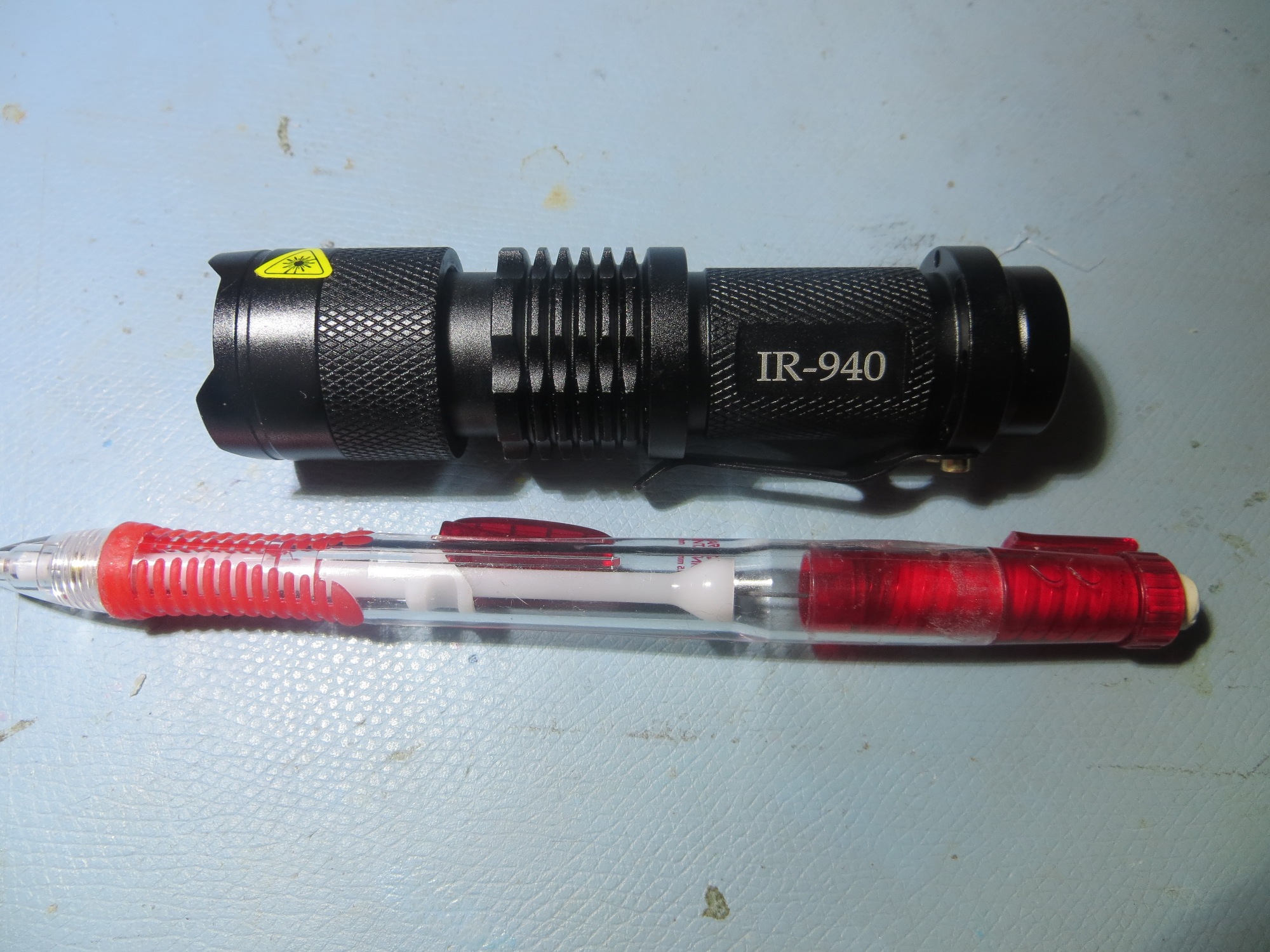
IR-940 IR Flashlight
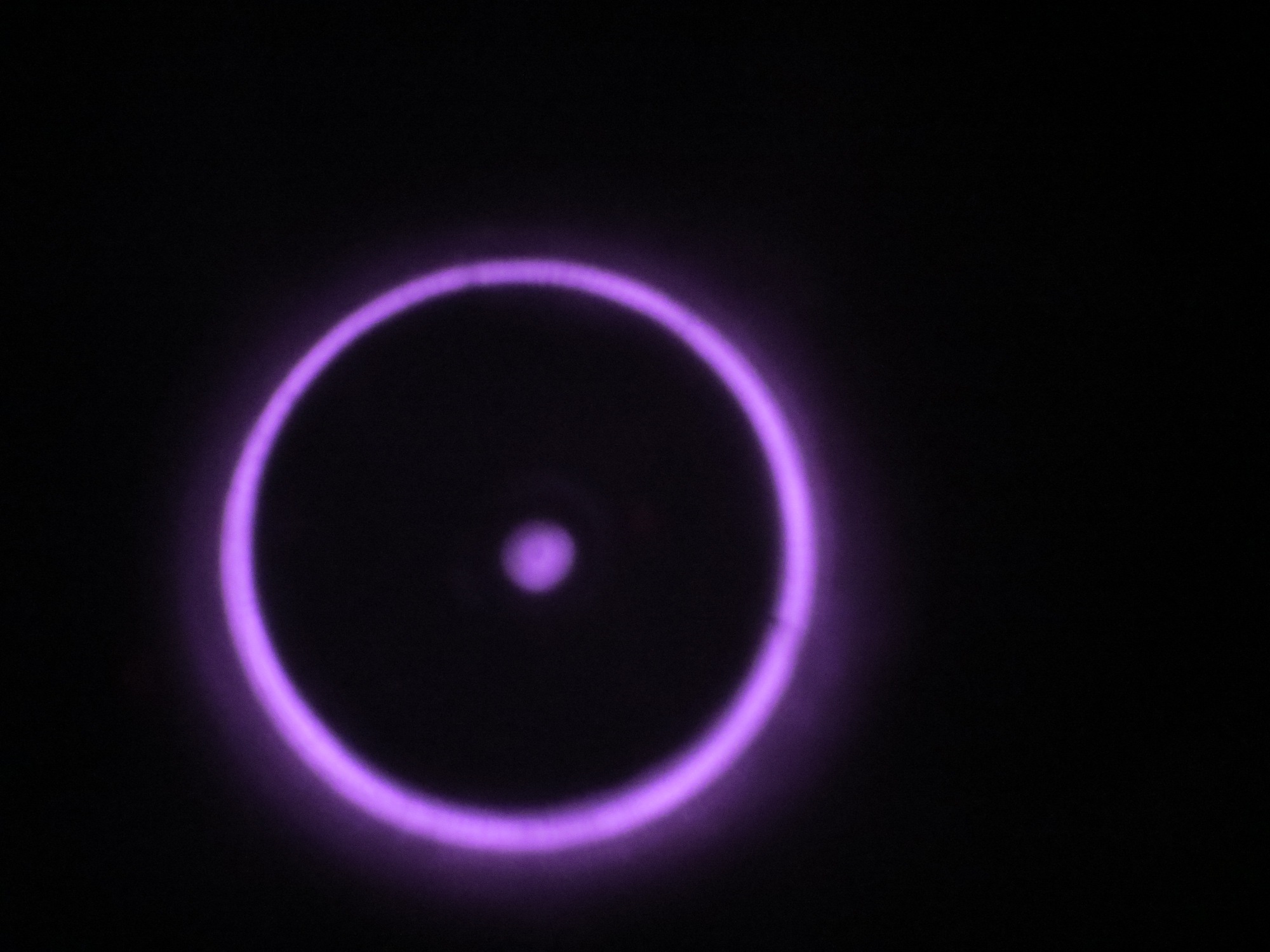
I ran a small series of tests to see if the adjustable optics really made a difference, and discovered that they did. As shown below, the spot beam is noticeably smaller and more intense than the other settings. Interestingly, the illumination pattern at the ‘wide’ setting is almost undetectable – it would be easy to conclude that the flashlight was actually turned OFF, when in fact it was still ON, but with a broad-beam pattern.
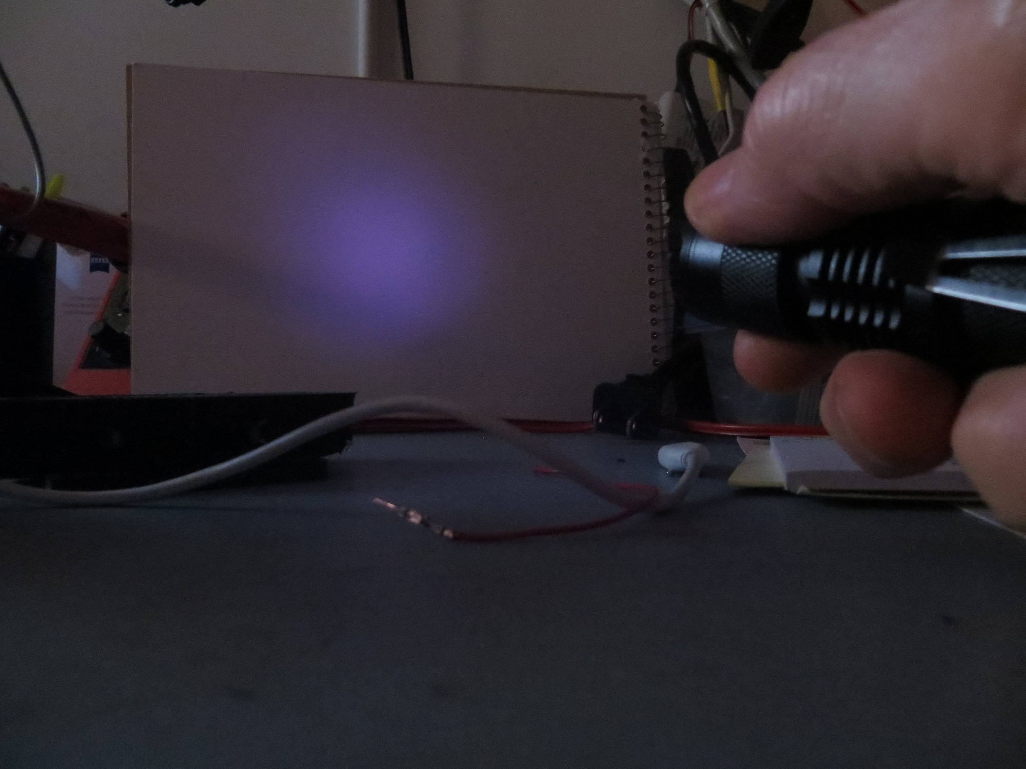
IR-940 flashlight at the most narrow-beam setting
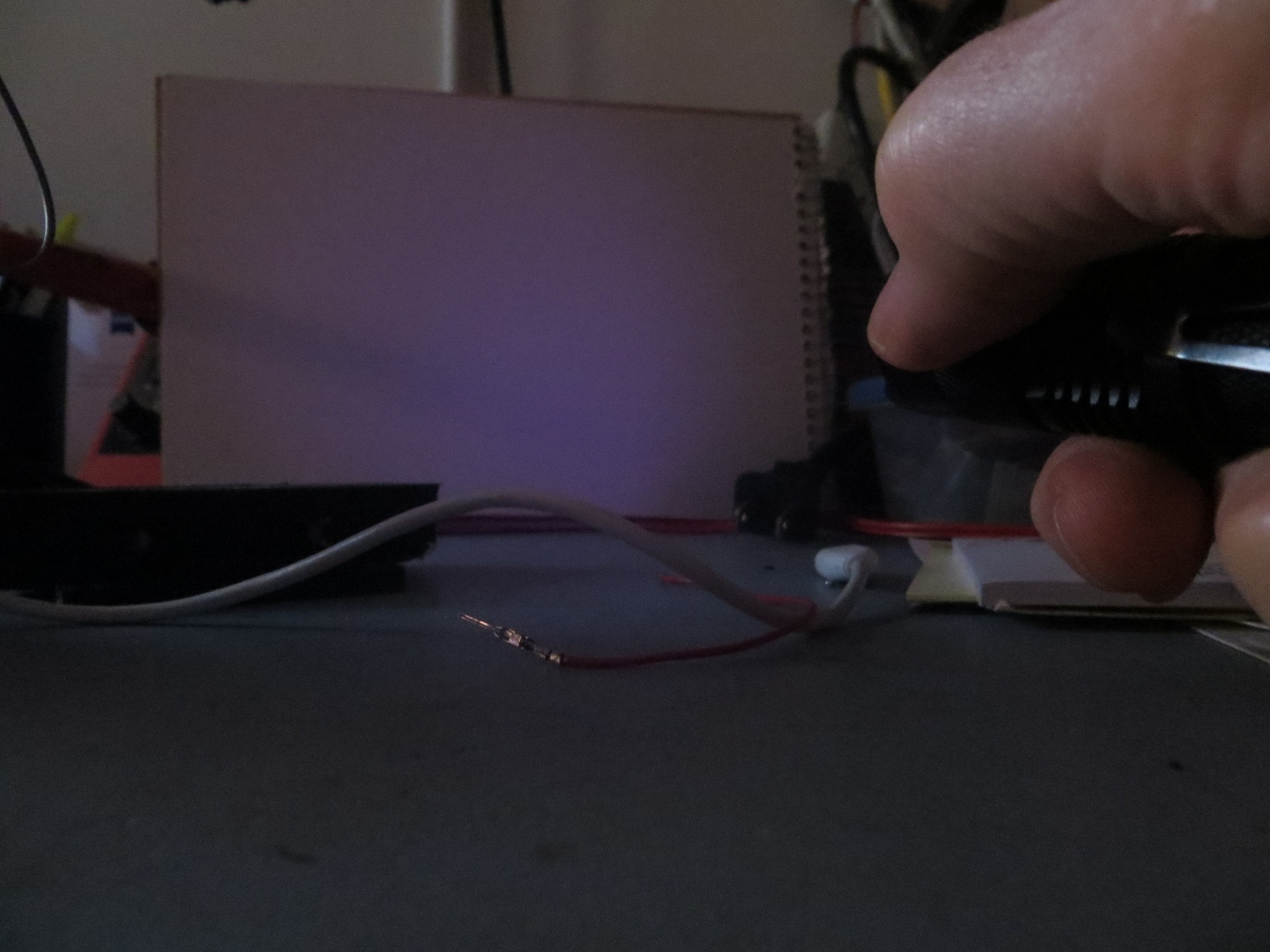
IR-940 flashlight halfway between the narrowest and widest settings
IR-940 flashlight at the widest setting
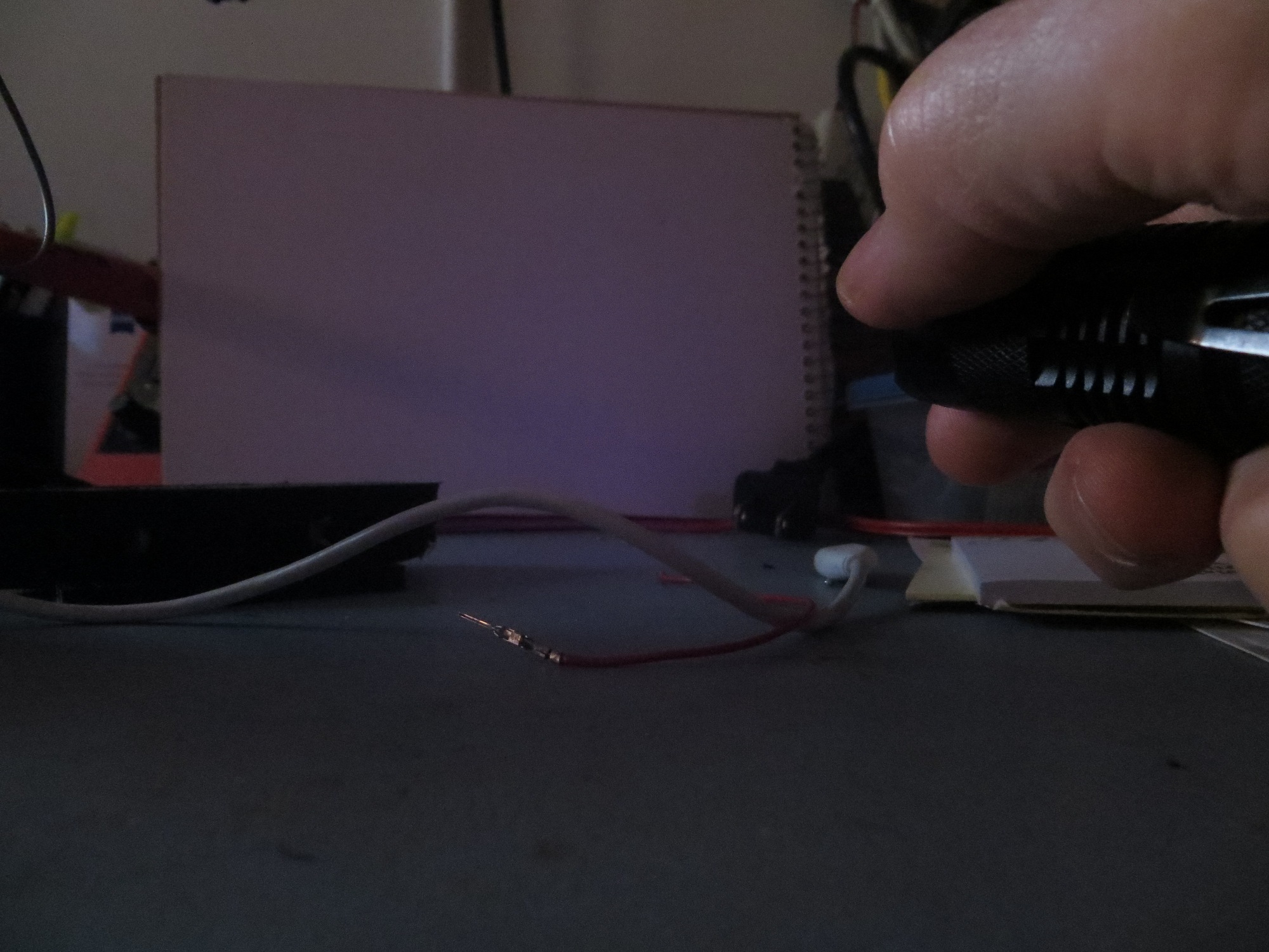
After investigating the flashlight’s physical construction for a bit, I figured out that I could simply hacksaw off the battery compartment, leaving only the front optics adjustment section, and of course the 3-LED module itself. The following photos show the result
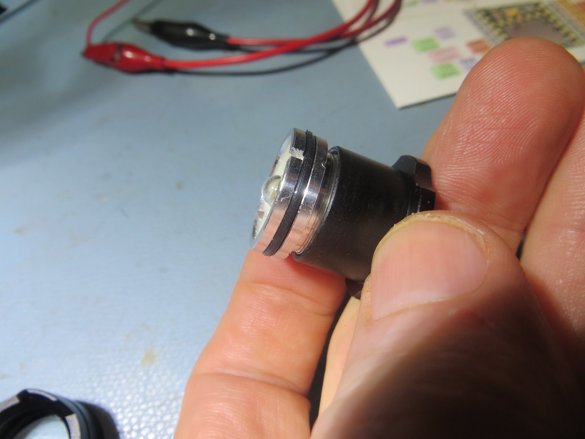
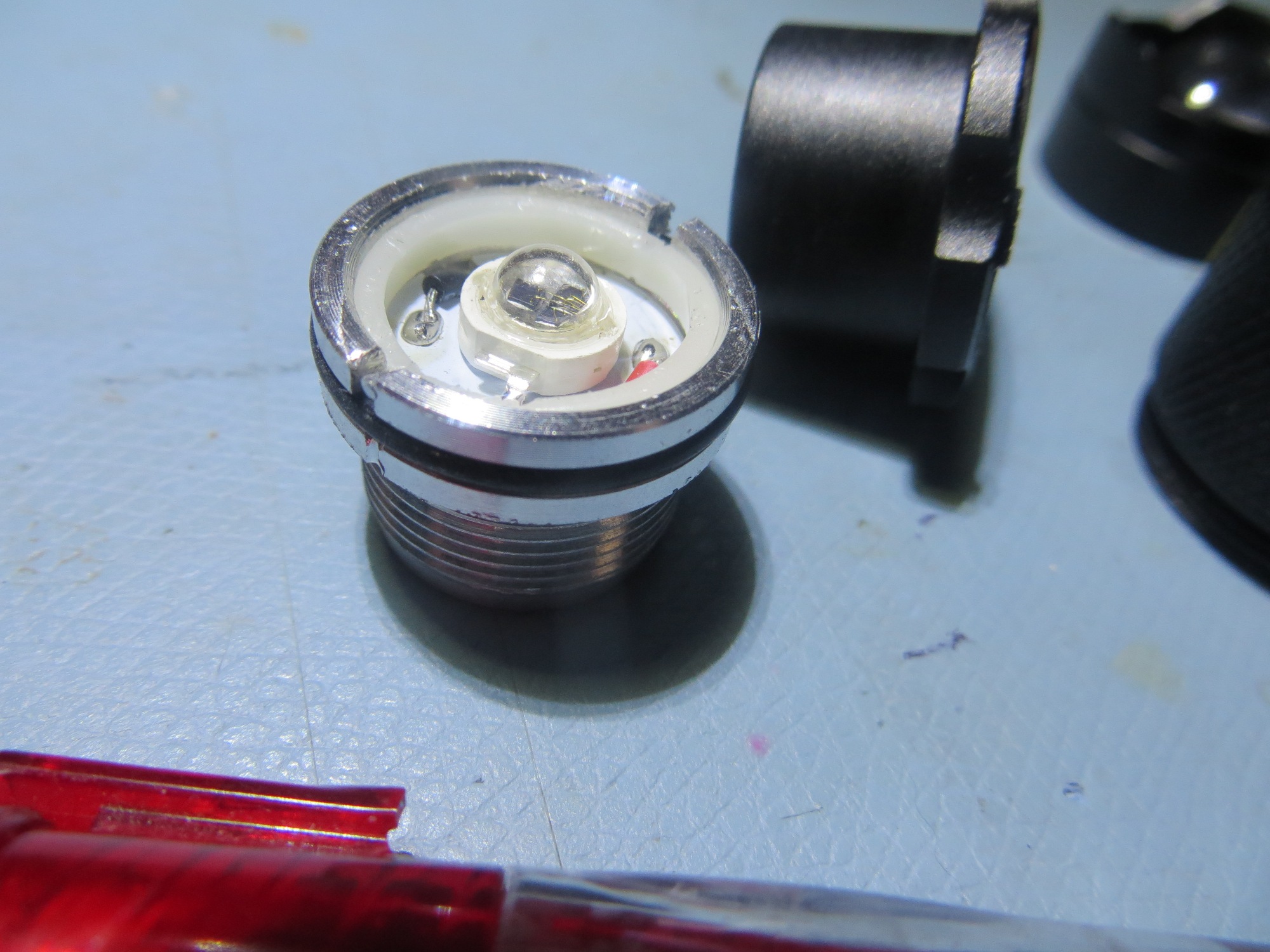

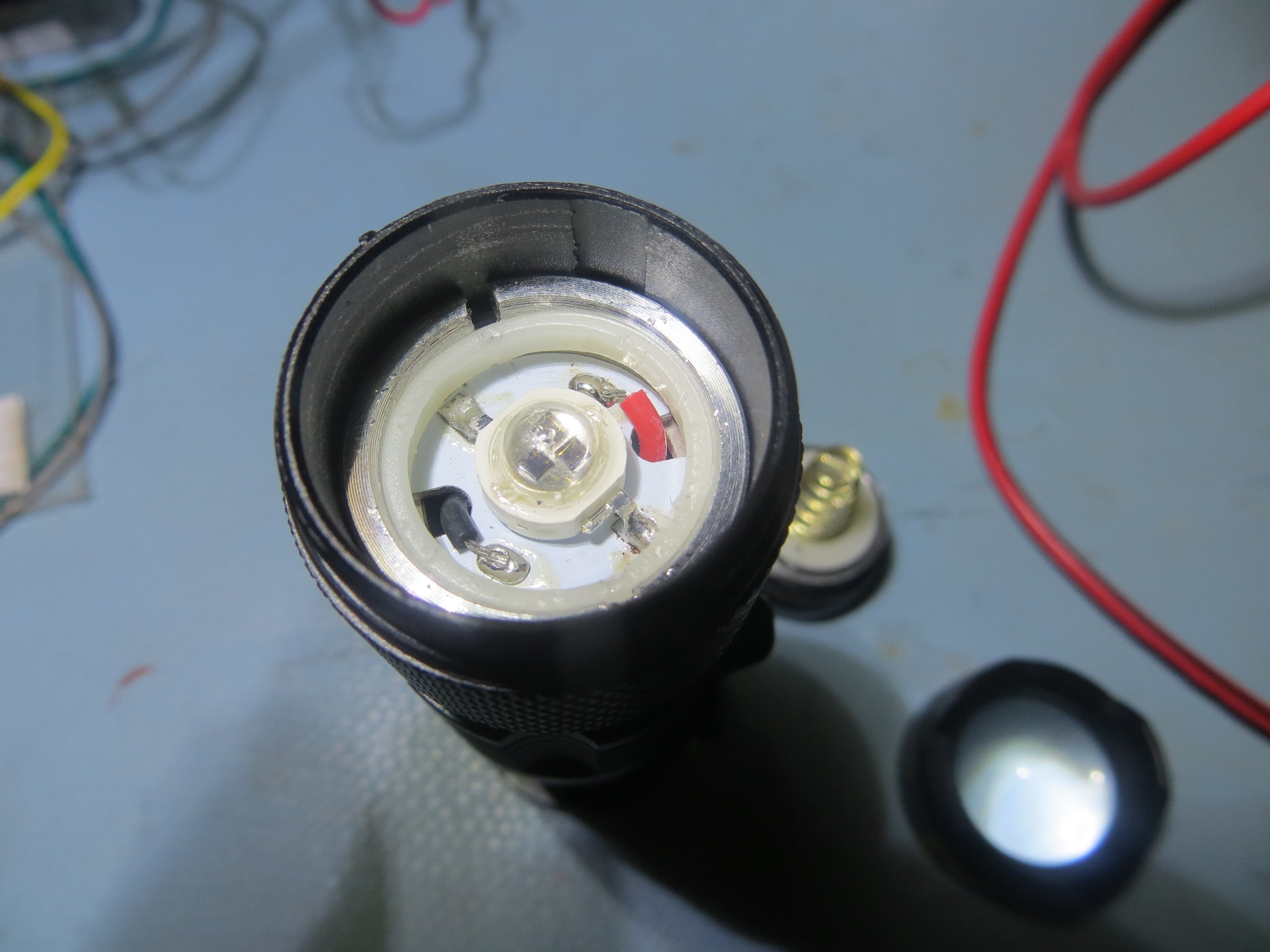
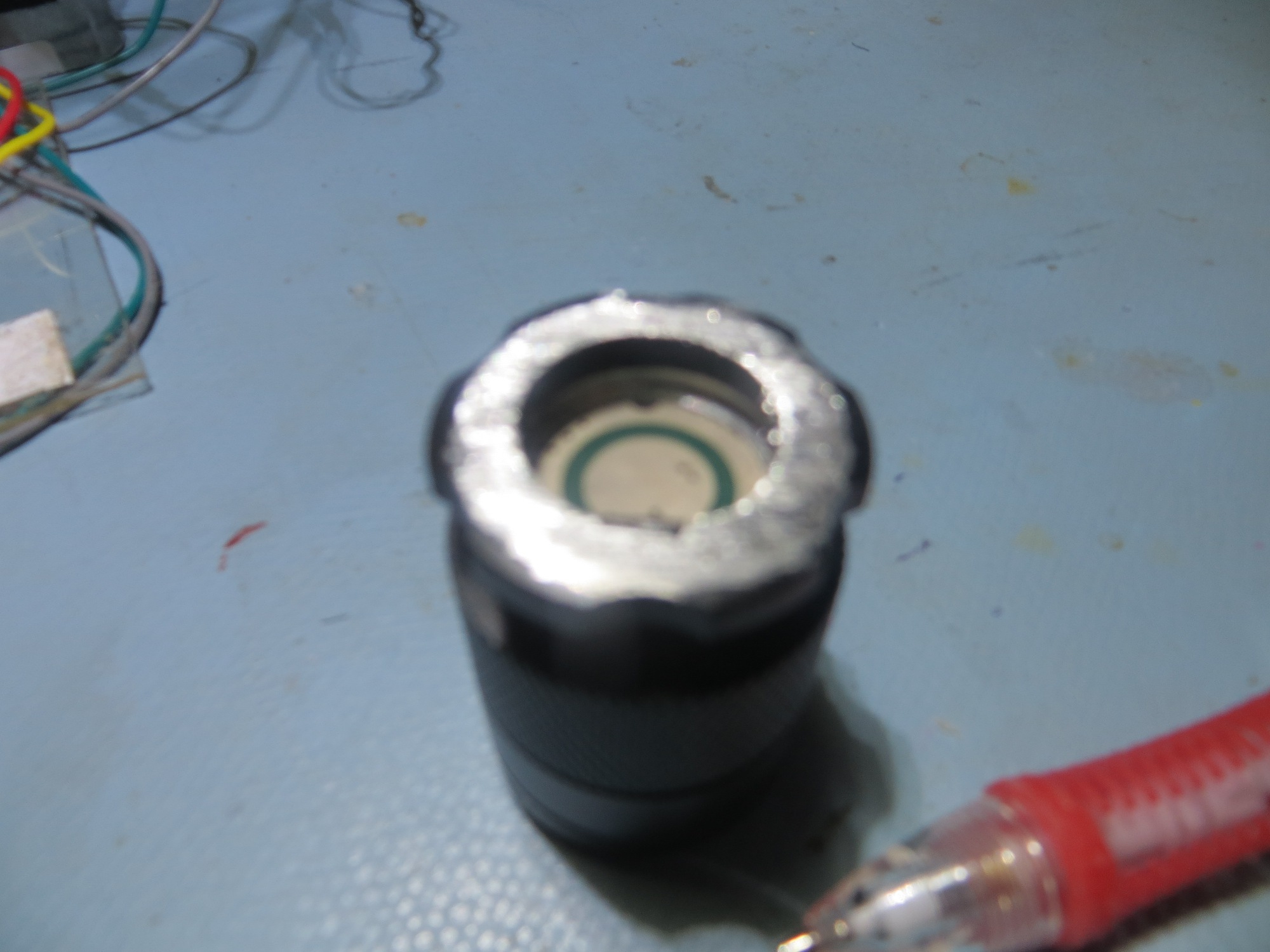
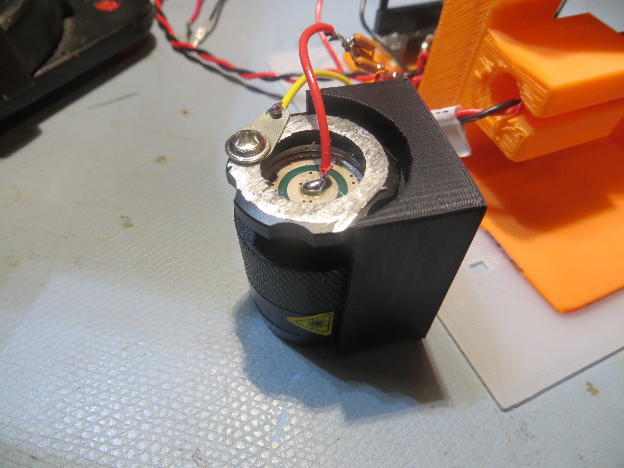
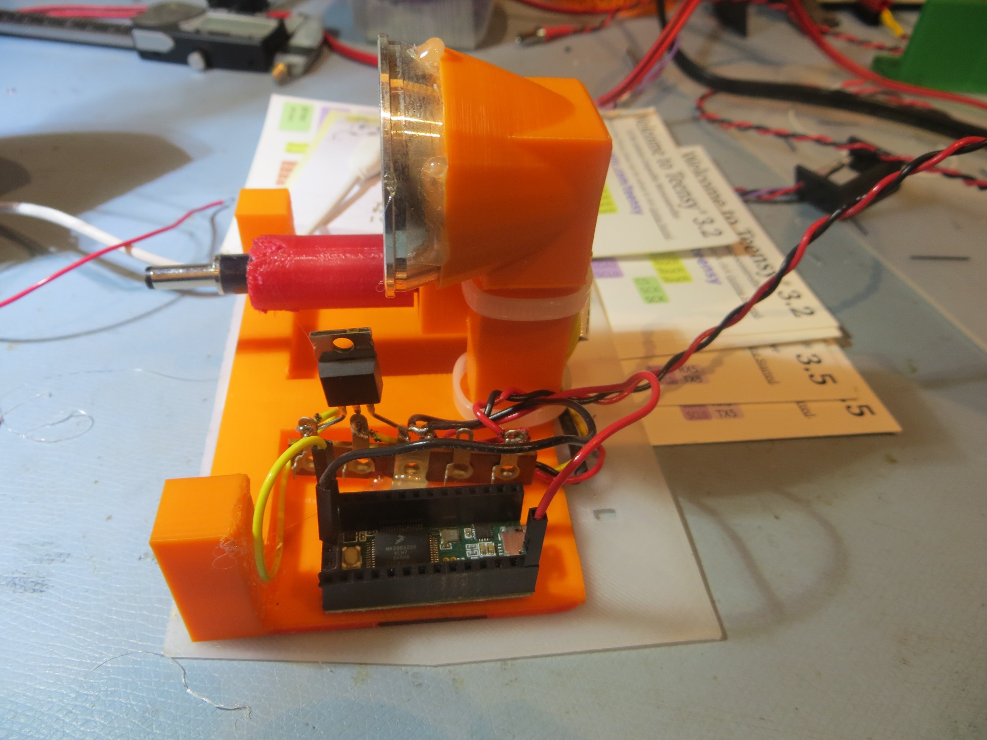
IR flashlight LED and optics section wired into charging station transmit module. The black plastic piece is a prototype of the holder to be used in place of the current reflector
I ran some simple distance tests using my digital camera as an IR sensor. With the room lights off, I could easily detect the flashlight output from up to 5 m (this was as far away I could get without too much trouble), as shown below

IR flashlight from across the room
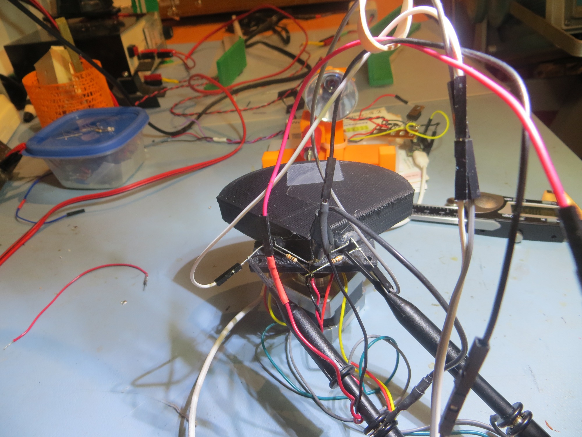
Then I redesigned the charging station module to accoMmodate the IR flashlight head, as shown below.
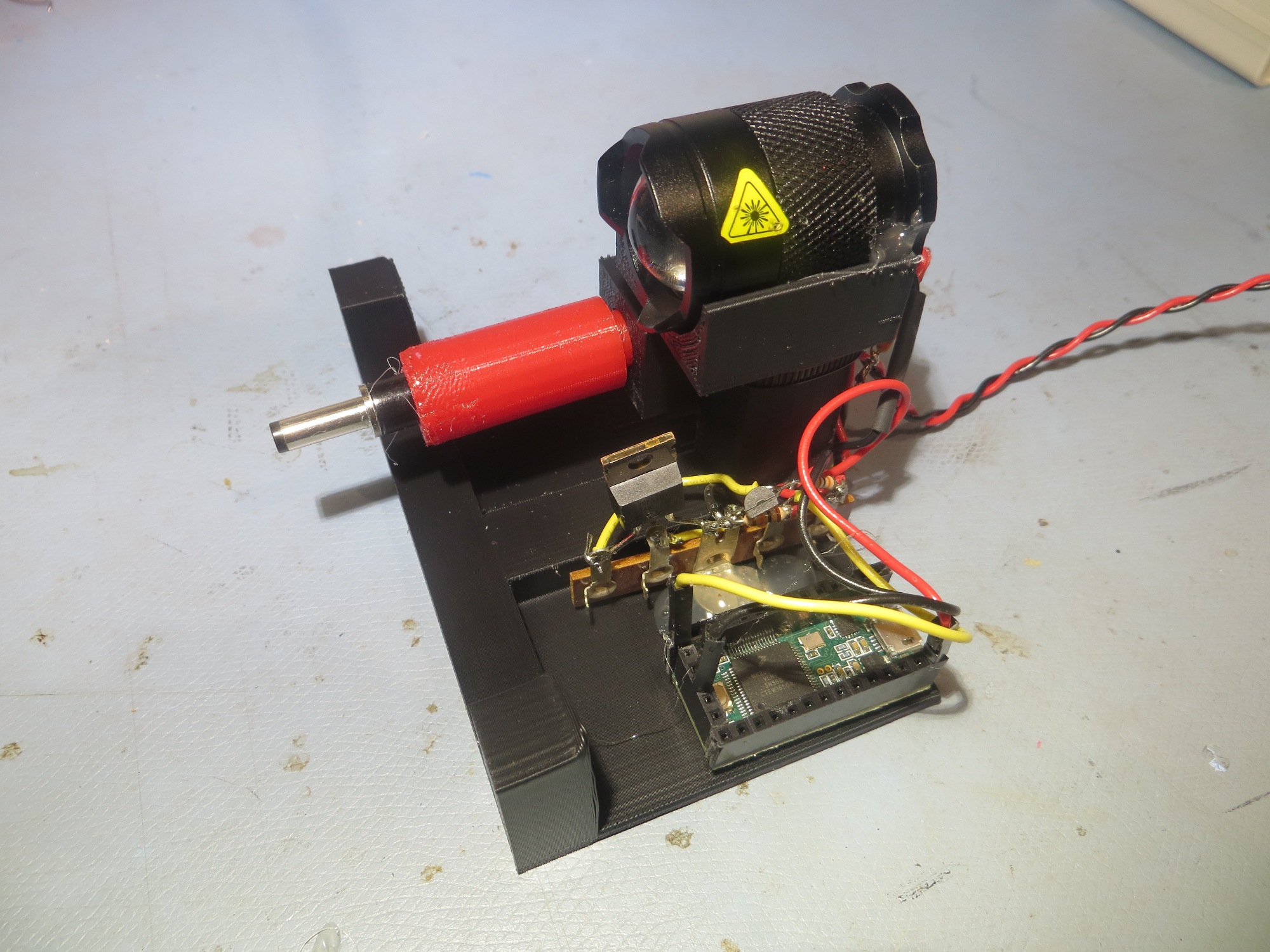
Charging station module with IR flashlight head installed
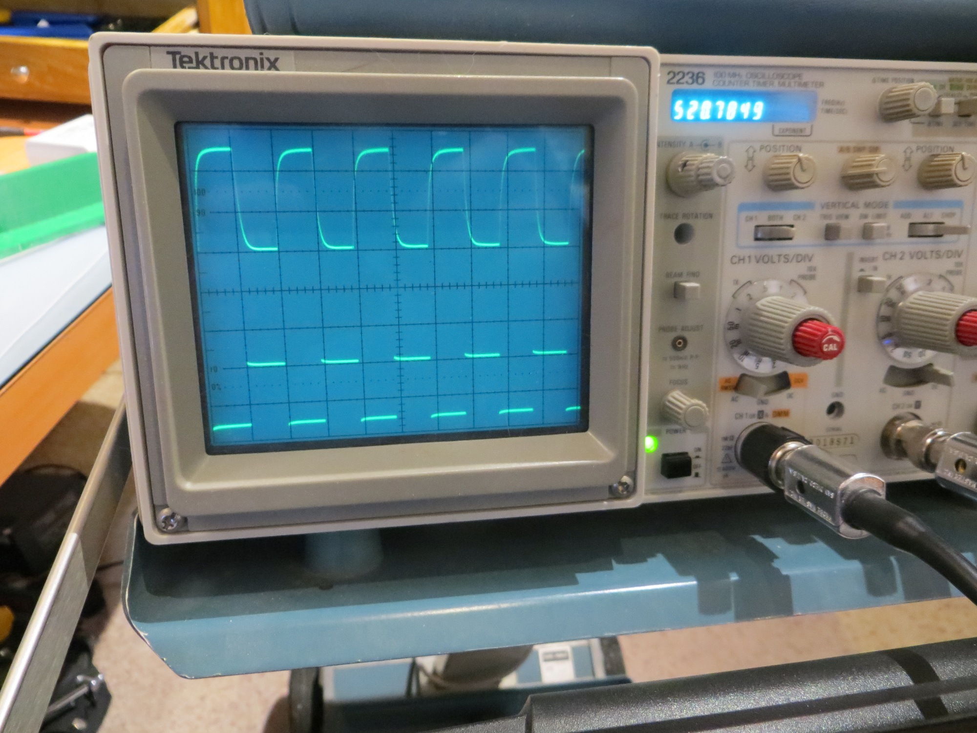
After getting the flashlight head installed on the charging station module, I ran some azimuth tests with the V10 sunshade, as shown below
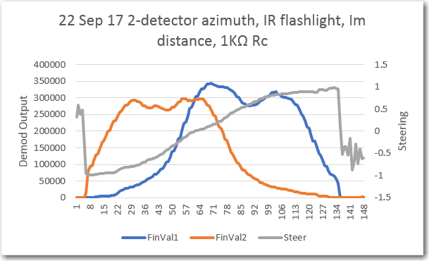
-90 to +90 degree azimuth scan at 1m: 2ea SFH-314 phototransistors with 1KΩ Rc using the V10 sunshade and the IR flashlight head
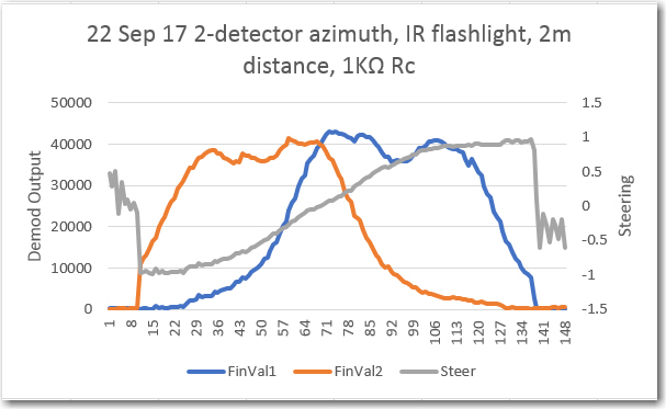
-90 to +90 degree azimuth scan at 2m: 2ea SFH-314 phototransistors with 1KΩ Rc using the V10 sunshade and the IR flashlight head
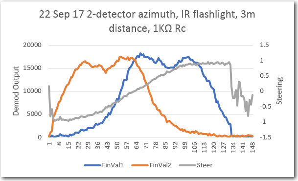
-90 to +90 degree azimuth scan at 3m: 2ea SFH-314 phototransistors with 1KΩ Rc using the V10 sunshade and the IR flashlight head
As can be seen from the above plots, the IR flashlight idea is definitely a winner. Even with the detector Rc reduced to 1KΩ the square-wave modulated IR signal can be successfully demodulated from at least 3m away. All three plots above are essentially identical, except for the scale. So, if needed, the Rc value could probably be further reduced, and/or the flashlight drive current could be lowered.
Phototransistor azimuth pattern alignment:
In the ‘original’ (V9) ‘crushed funnel’ sunshade design, the phototransistors were aligned with about 70 º offset, i.e with a 110 º internal angle between the two back walls. This resulted in the following azimuth plot
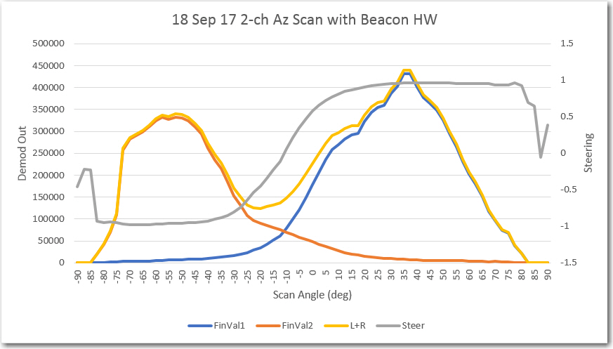
Azimuth scan using 2ea SFH-314 photo transistors
This indicated to me that I needed to bring the two phototransistor boresight angles more in parallel, thereby moving the two individual azimuth responses toward each other, filling the gap between them. To accomplish this, I printed up another ‘crushed funnel’ sunshade (V10), with the phototransistors offset 50 º instead of 70 º (i.e. an internal angle of 130 º). This piece was used for the 1m, 2m, and 3m plots above (repeated below for comparison purposes)
-90 to +90 degree azimuth scan with SFH-314 phototransistors using the V10 sunshade and the IR flashlight head, 1m distance
Comparing these two plots, it looks like I overshot a bit with my adjustment, as now the two individual phototransistor responses are too close together to produce a decent slope on the ‘steering’ (L-R)/(L+R) curve shown above in gray. Fortunately, it costs essentially zero to produce yet another ‘crushed funnel’ design, this time with an offset midway between the V9 (about 70 º) and V10 (about 50 º) versions, i.e. an offset of about 60 º (V11). The image below shows the result on my 1m range
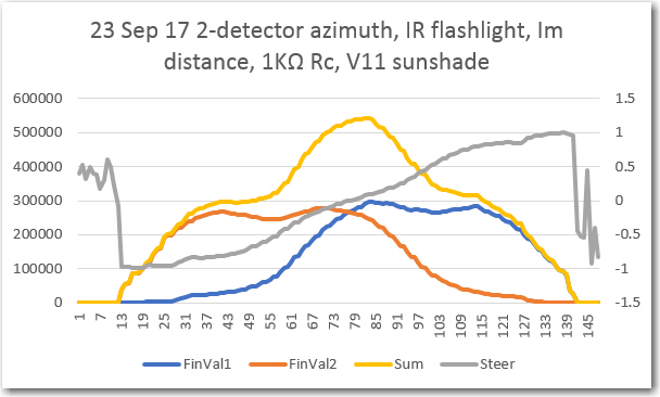
-90 to +90 degree azimuth scan with SFH-314 phototransistors using the V11 sunshade and the IR flashlight head, 1m distance
The above plot definitely shows an improvement in the phototransistor azimuth response alignment, and this might well be the one that I want to go with. However, it makes me a little suspicious of the original V9 data, as the V9 and V11 offsets are almost the same (70 º for V9 vs 60 º for V11). Maybe the only real difference between V11 & V9 is the Rc value? To test this theory, I re-ran the V9 setup with a 1K vs 10KΩ, with the following results.
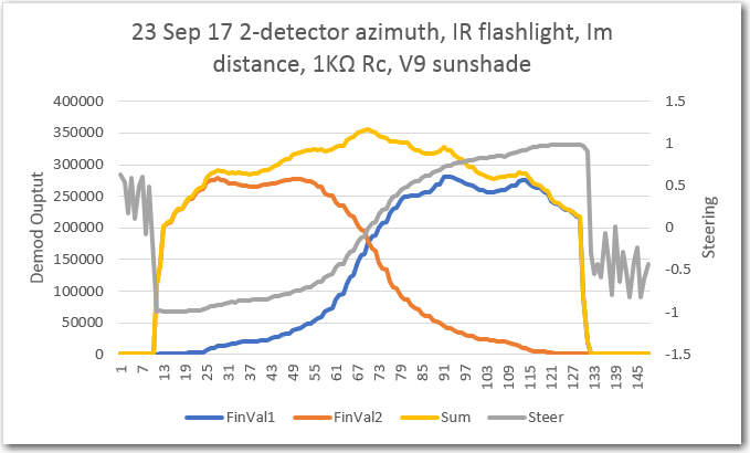
-90 to +90 degree azimuth scan with SFH-314 phototransistors using the V9 sunshade and the IR flashlight head, 1m distance
As can be seen from the above, my suspicions about the original data were well-founded; the V9 scan with the 1KΩ is just about perfect; the two detector az responses cross at about 1/2 amplitude, and the steering curve is smooth and steep in the boresight region. So it appears that something else was responsible for the anomalous V9 results – either the use of a 10K Rc or the fact that the original V9 results were acquired with the TSAL-6200/reflector setup versus the IR flashlight setup. Just for completeness, here’s a shot of all three ‘crushed funnel’ designs.
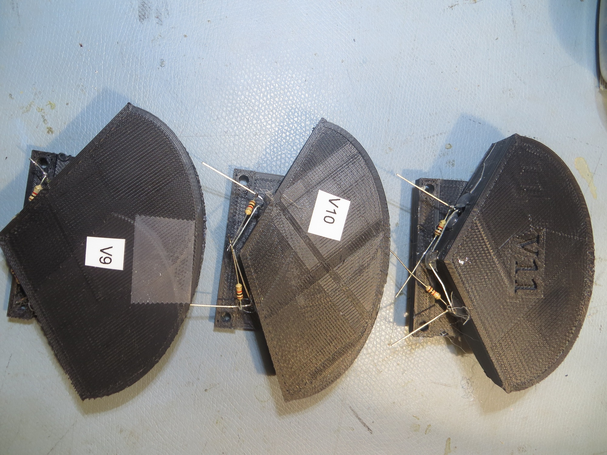
All three ‘crushed funnel’ sunshade designs. As it turns out, V9 was the winner
At this point, I think I have just about everything I need to integrate the square-wave modulation detection/homing scheme onto the robot; I’ve got a good (V9) sunshade, an excellent IR source with the modified IR flashlight, and a well-tested Teensy 3.2-based demod/homing module. I think the next step will be to mount the sunshade/detector unit and the demod module on the robot, modify the main robot controller software to acquire steering data via an I2C channel, and then do some homing tests.
Stay tuned,
Frank