Posted 20 August 2017
I’m writing this post from our Kids’ place in St. Louis, which just happens to be in the path of totality for the upcoming solar eclipse. As usual, I brought my project stuff with me so I can work in the off moments, but this trip has a bonus in that I have managed to suck my 14 year-old grandson Danny into helping me with the robot project. He also has my old PrintrBot ‘Simple Metal’ 3D printer, so he is able to print up new IR detector holders as required.
So, the first thing we did was to print up a new holder with a 30 º angular offset for the detectors; this is something I forgot to do with the previous model. With this setup, we got the following results from an azimuth scan.
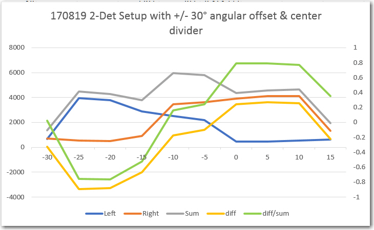
Azimuth scan for 2-detector model with 30-deg angular offset and center divider
meanwhile, my friend and mentor John Jenkins came up with a set of simulated azimuth response curves (shown below) that showed that the center divider (apparently originally intended to make steering more responsive) was more of a liability than an asset. Turns out (at least according to John’s results) that removing the divider makes the (diff/sum) ratio curve smoother and more linear in the critical boresight region.
 Loading...
So, we printed up a new holder with the center divider removed (and in the process made the walls thicker to block IR transmission through the material), and took some more measurements.