Posted 17 August 2017
In my last post on this subject, I noted that the output from one of the four IR LEDs used in the current arrangement was considerably larger than from the others (like several times larger). This was a bit disturbing, to say the least, as proper homing operation depends in large part on having consistent responses from all four sensors. After some troubleshooting, I came to the conclusion that the culprit here is the narrow beamwidth of the SFH-309FA IR phototransistors I am using. I originally chose this unit for it’s narrow beamwidth as a replacement for the IR photodiodes in the OSEPP IR Follower module (see this post). This setup seemed to work OK, but as I developed the ‘sunshade’ addition to suppress unwanted interference from sunlight and overhead incandescent lighting, and the reflector idea for the charging station, I think I inadvertently exacerbated the effect of narrow beamwidth in the vertical dimension. When the now-narrower transmit beam is well-aligned with the narrow receive beamwidth of a particular phototransistor, the response can be several times higher than when they are not aligned. A further complication is that just statically aligning the transmitter beam with the receiver beam may not be sufficient, as there may be some physical misalignment of the charging station with the robot as the robot approaches.
Independently of the above, a lot of water has flowed over the dam in the ten months since the original implementation of the 4-element phototransistor array. Most importantly, in collaboration with my friend and mentor John Jenkins, I have successfully implemented a two-channel ‘degenerate N-path band-pass filter’ to allow for discrimination between unwanted IR interference and the desired charging station IR beacon. Now the homing beacon will be modulated by a 520Hz squarewave, the center frequency of the BPF. For this implementation, only two IR detectors are needed, rather than the four that I currently have. In my initial attempt at integrating the new BPF capability into the robot, I simply averaged the two left and the two right phototransistor outputs to simulate a two-element setup, but as noted above this ran into problems due to the narrow vertical beamwidths of the SF309FA devices.
Rather than try and get all four phototransistors aligned with each other and with the charging station transmit beam, I decided to punt on the entire 4-element array design and start over again, using two detectors with wider beamwidths and a sunshade with a center divider, as shown below:
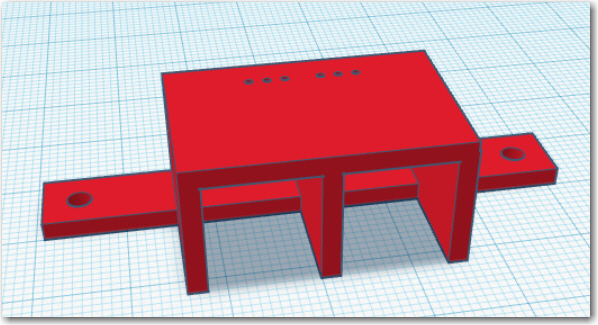
2-detector sunshade for use with TSL267 IR-to-voltage devices
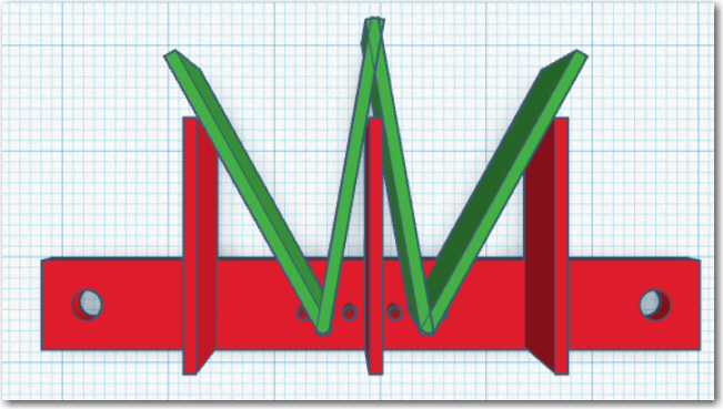
2-detector sunshade, top view showing interior and exterior angles
In the above screenshot, the green plates represent the TSL267 beamwidths, as modified by the walls of the sunshade. The front-to-back dimension of the sunshade was set to allow a 30 º exterior beamwidth, and the location of the device with respect to the center divider was set to allow a 10 º overlap between left and right detectors. These values were somewhat arbitrary, but I think they represent a good starting point.
After a couple of false starts, I got a decent sunshade printed out, and mounted two TSL267s. Then I connected them to my Teensy 3.2 and ran an azimuth using my 1.8m range, as shown in the photos below.
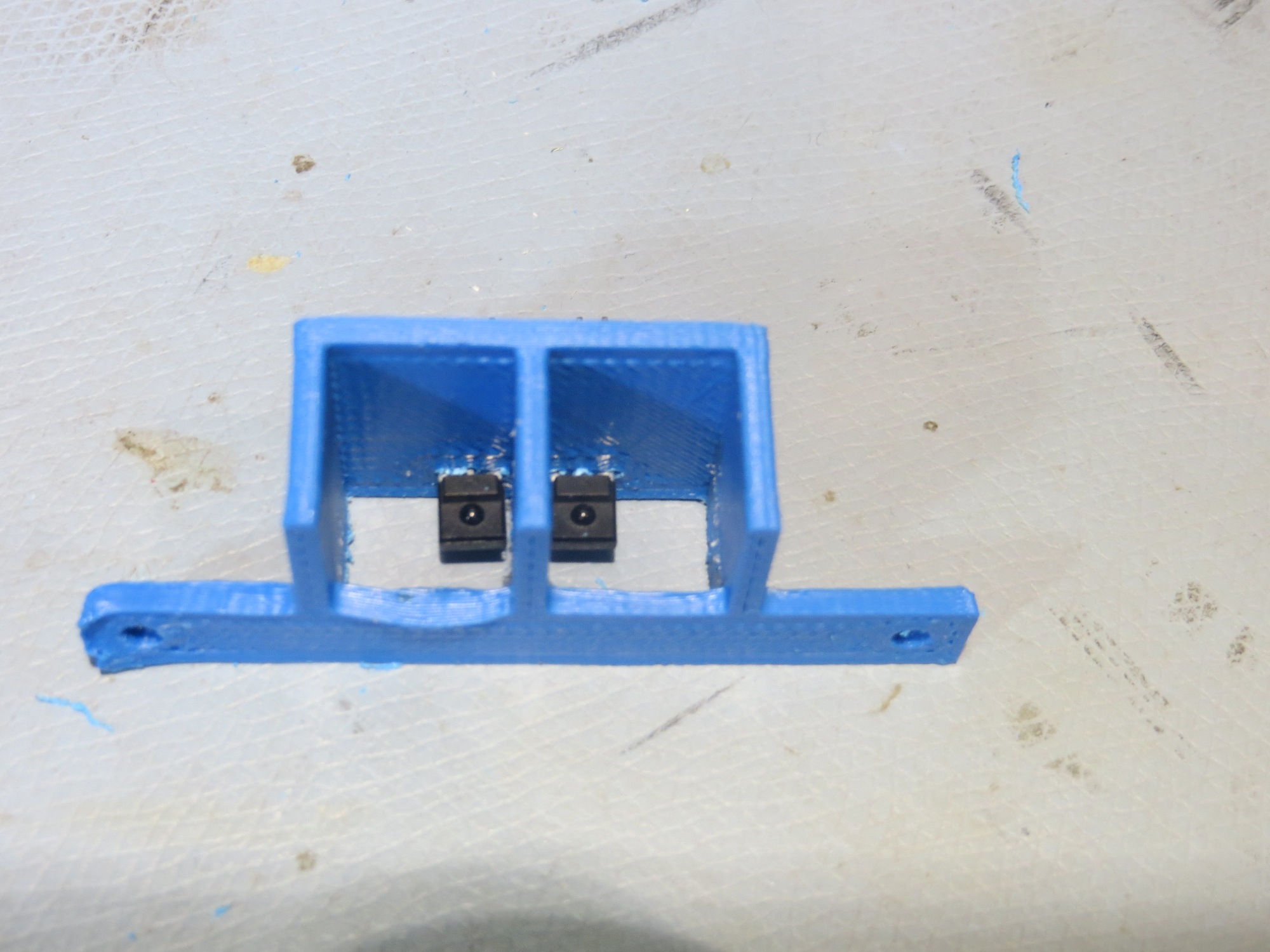
Front view of new sunshade, with two TSL267s installed
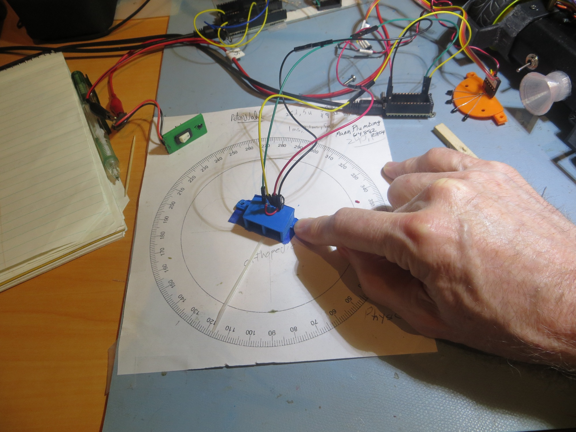
Sunshade with 267s installed and connected to Teensy 3.2 for azimuth testing. Note ‘sta-strap’ pointer
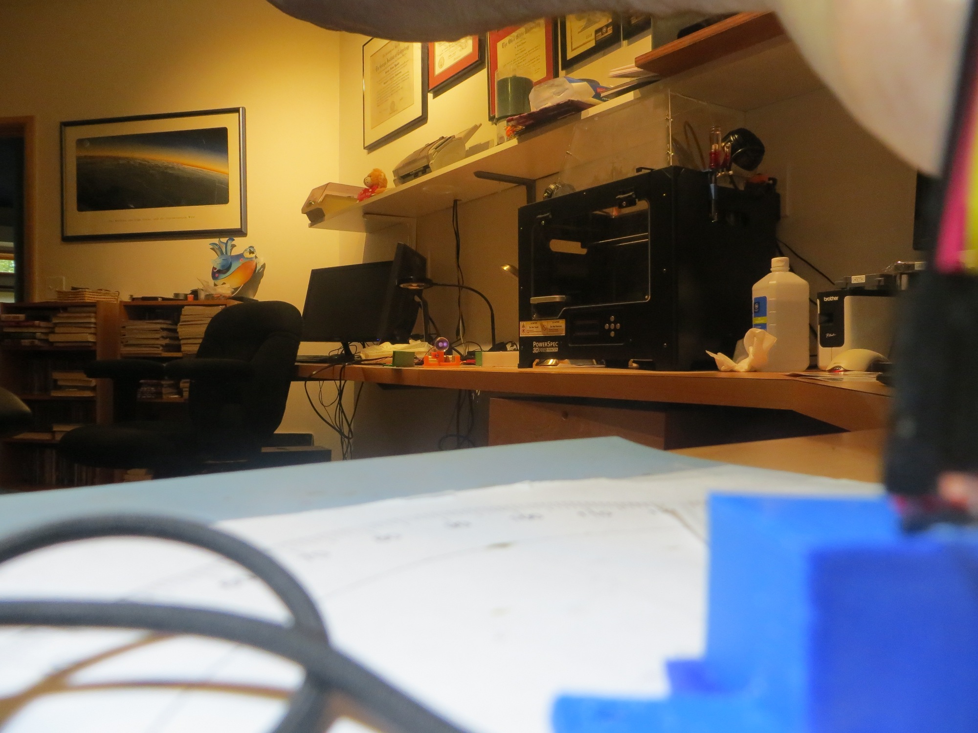
1.8m range. Note charging station in background (orange assembly just to left of 3D printer) with IR LED at center of reflector
As shown below, the azimuth response is pretty close to the predicted values – about 35 º either side of boresight, with about 10-20 º overlap between the left and right responses. A nice benefit of switching to the TLS267 is the internal inverting op-amp, which produces an output with the same sign as the received field intensity. This will require a few modifications to the IR demodulation algorithm, but well worth the minor trouble.
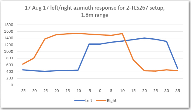
Azimuth response for 2-TLS267s installed in sunshade
Looking at the above plot, I’m not sure that the overlap region is narrow enough for good tracking. If I understand the dynamics correctly, the two channels will show the same demodulated value for +/- 15 º, so the system won’t know to correct within this range. I’m thinking I would like to have this be more like +/- 5-10 º maximum. So, I will print another version of the sunshade with a 10mm longer front-back dimension and see how it works.
Stay tuned!
Frank