Monthly Archives: August 2017

IR Homing Module Integration, Part V


Posted 31 August 2017

The goal for this part of my evil master plan to bend my robot to my will (or at least get it to breakfast) is to demonstrate that I can utilize steering information generated by the 2-channel N-path digital band-pass filter to track the movement of a square-wave modulated IR source.

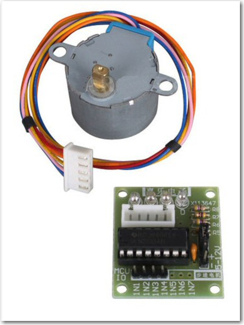
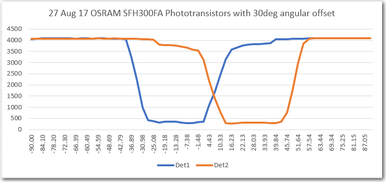
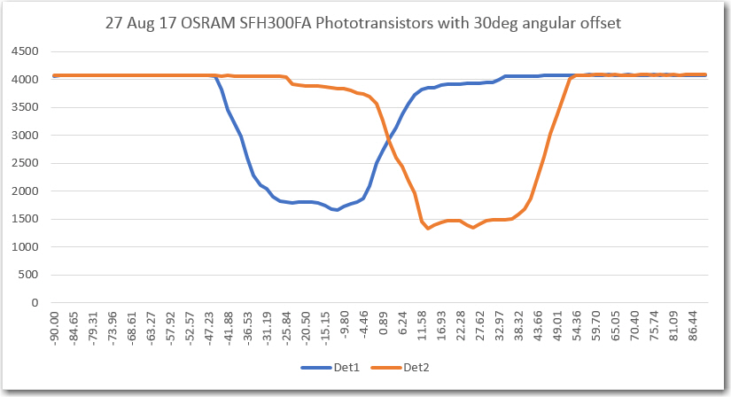
As you may recall from a post long ago in a galaxy far away, I started this particular tangential odyssey as a result of a visit from my old friend and mentor John Jenkins.  I mentioned to him that my robot was having some difficulty homing in on a charging station with an IR beacon, due to interference from sunlight and overhead incandescent lighting.  His recommendation at the time was to use a square-wave modulated IR beacon, and detect it using an ‘N-path digital band-pass filter.  Since that time, I have successfully implemented the receiver algorithm and am now working on integrating the whole thing back onto the robot.  In my last post  on this subject, I described how I created a rotary table using an Arduino Uno driving a cheap stepper motor via a ULN2003 driver module, and then used the rotary table to acquire azimuth scan data for the IR detector module that is to go on the front of the robot.

After getting all the azimuth scan stuff to work, and enjoying my new stepper motor super-powers, it occurred to me that the rotary table could also work as a way to test the homing performance of the system.  In the final configuration, the IR detector module will be mounted on the front of the robot, and the system will home in on a fixed position IR beacon by modulating the left & right wheel motor speeds.  However, I could turn that around a bit and use the current rotary table setup where the IR detector is fixed (but can rotate) and the IR beacon can be moved to simulate tracking/homing perturbations.  Then the stepper motor would be used to rotate the IR detector module right or left to follow the moving IR source.  If I can get the stepper motor/IR detector module to properly follow the moving beacon source, then I can work many of the bugs before working with the entire robot.

In a previous post, I demonstrated I2C communications between two Teensy modules, so I planned to use this method to transmit steering values from the IR homing module to the rotary stepper motor controller.  Unfortunately, I ran into a problem right away, because the Uno I was using to control the stepper motor runs on 5V logic, and the Teensy modules all run on 3.3V – oops!  I solved this problem by replacing the Uno with yet another Teensy 3.2 from my inexhaustible Teensy drawer (thank you again, Paul Stoffregen!).  This also allowed me to use the previous I2C master/slave demo code pretty much unaltered – yay!!

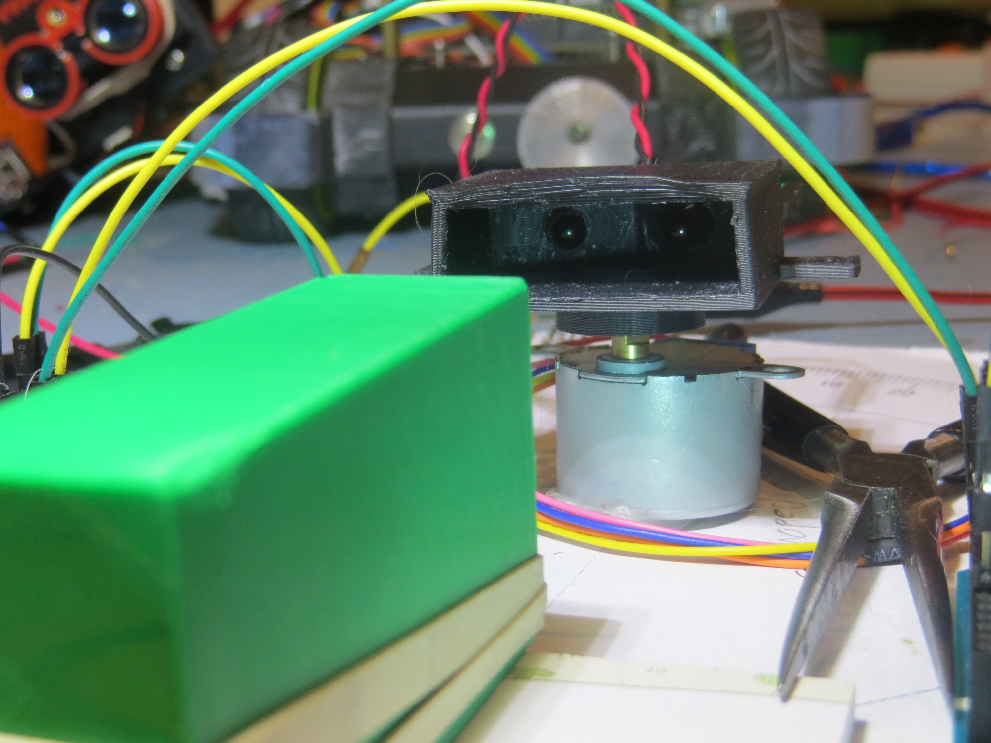
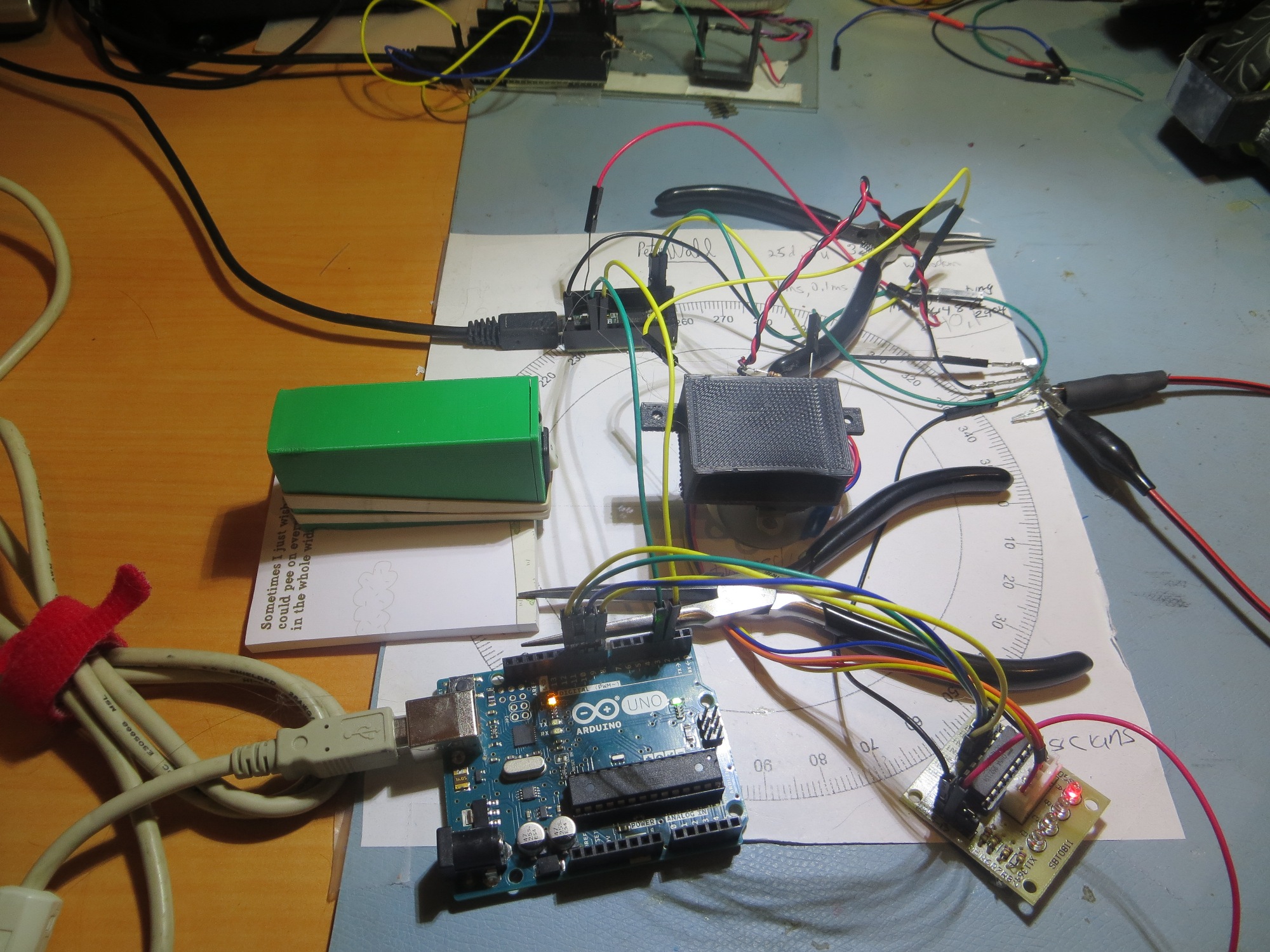
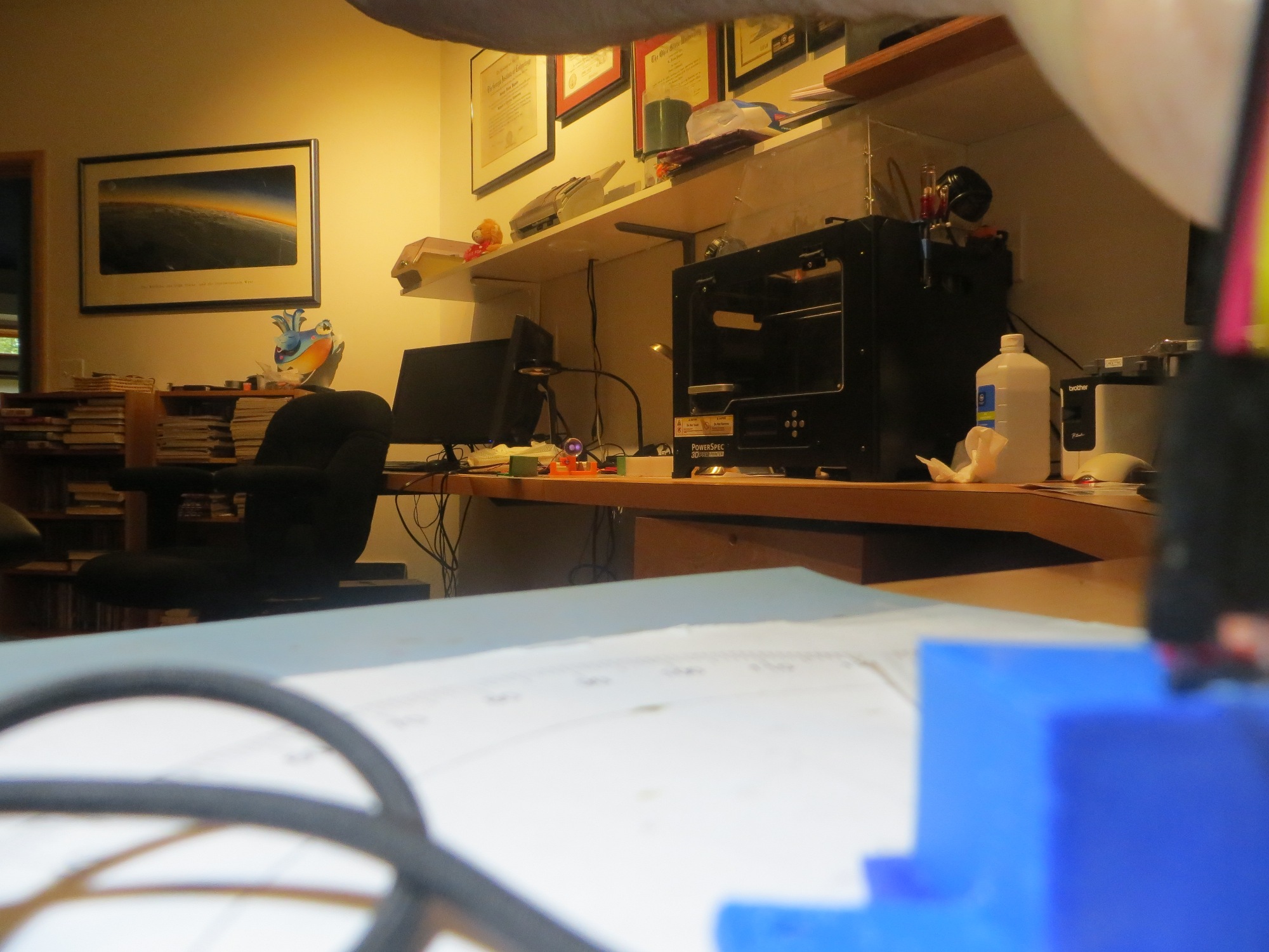
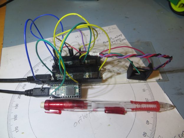
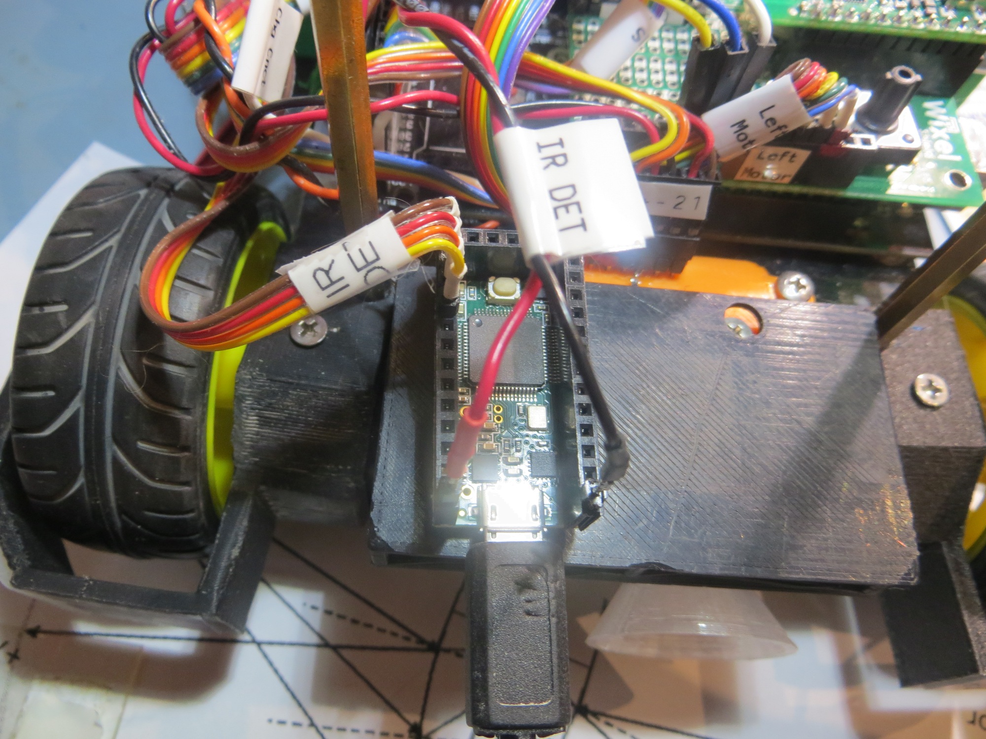
So, the first baby step in getting all this going was to verify that the Teensy 3.2 replacement for the Uno would indeed run the stepper motor via the ULN2003 driver, as shown below

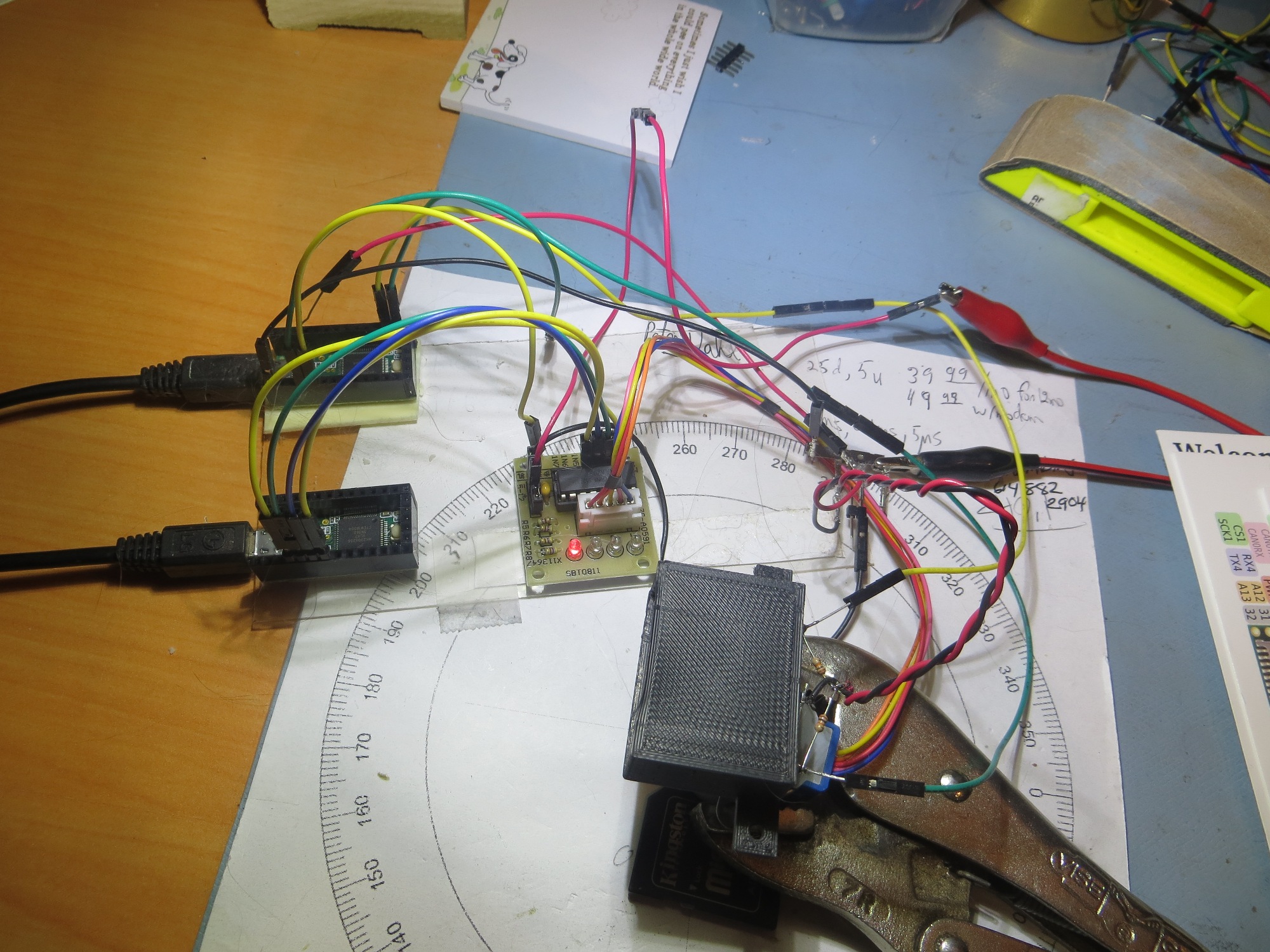
Teensy 3.2 used as rotator controller in place of Arduino Uno

Here’s a short movie demonstrating that the stepper motor can indeed be controlled using the Teensy.

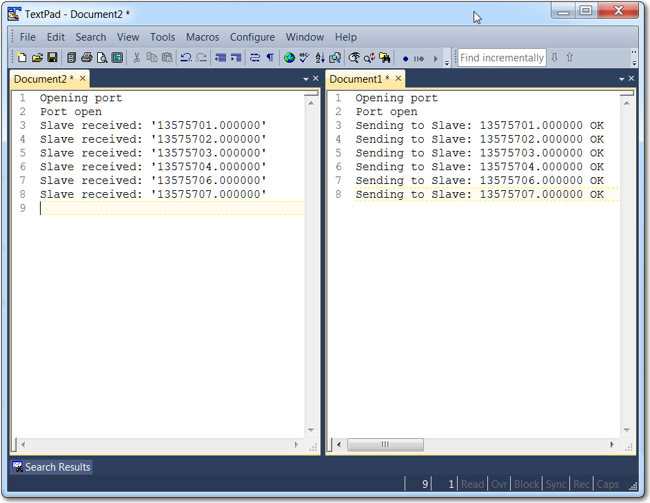
The next step is to integrate the code from my I2C Master/Slave example code that I used to produce the output described in  this post, so the rotary table movement  can be controlled by data transmitted over the I2C connection between the table controller and the IR Homing module.

01 Sept 2017 Update:

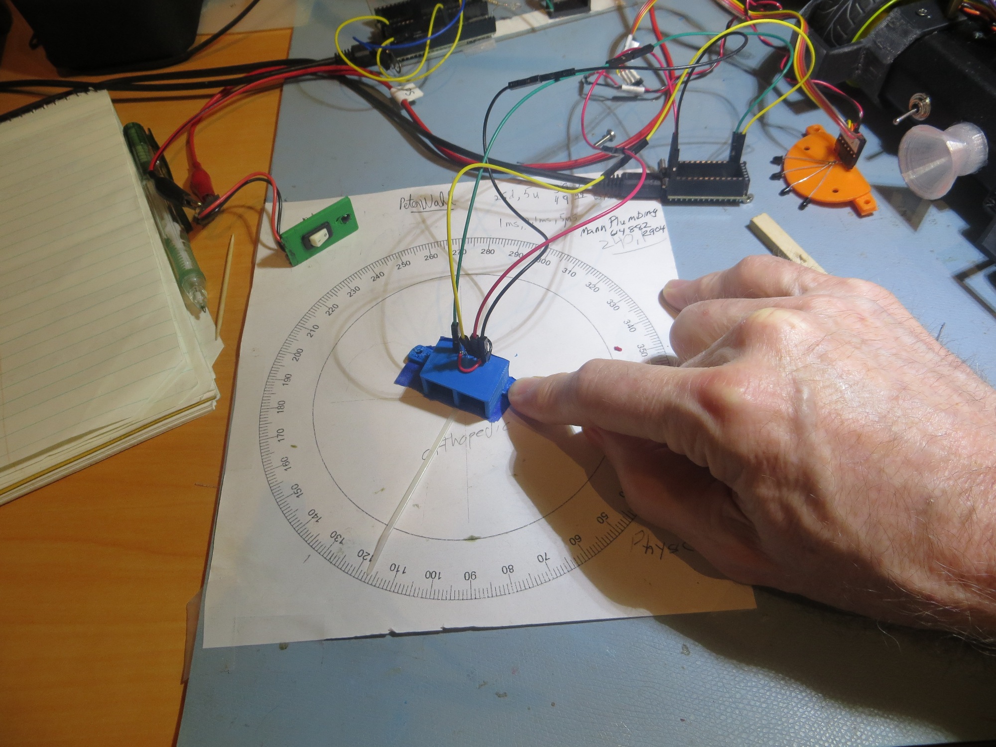
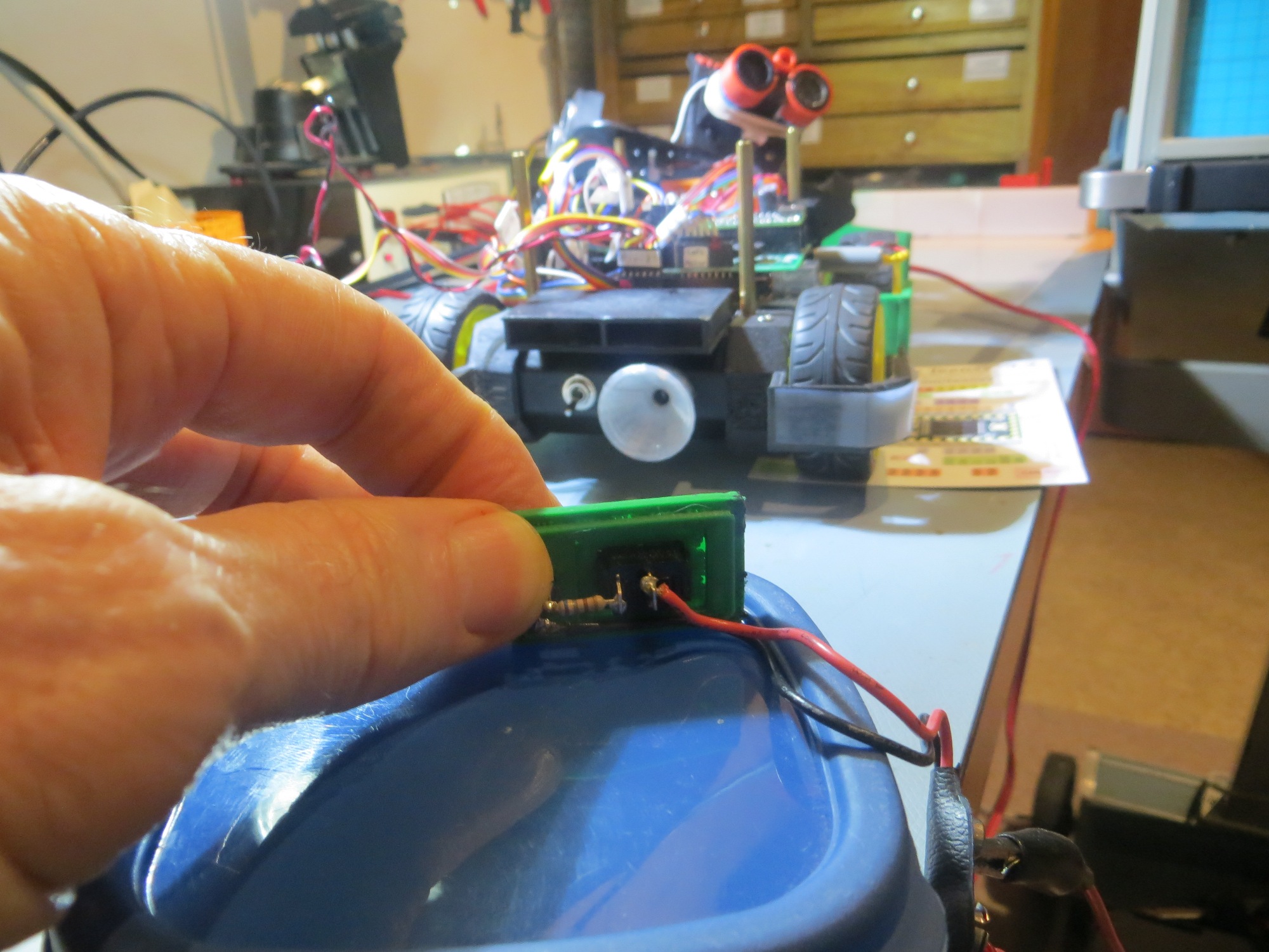
Turned out that getting the I2C master/slave code and the stepper motor code integrated wasn’t too hard.  Here’s a short video showing the sensor module tracking my square-wave modulated IR beacon transmitter

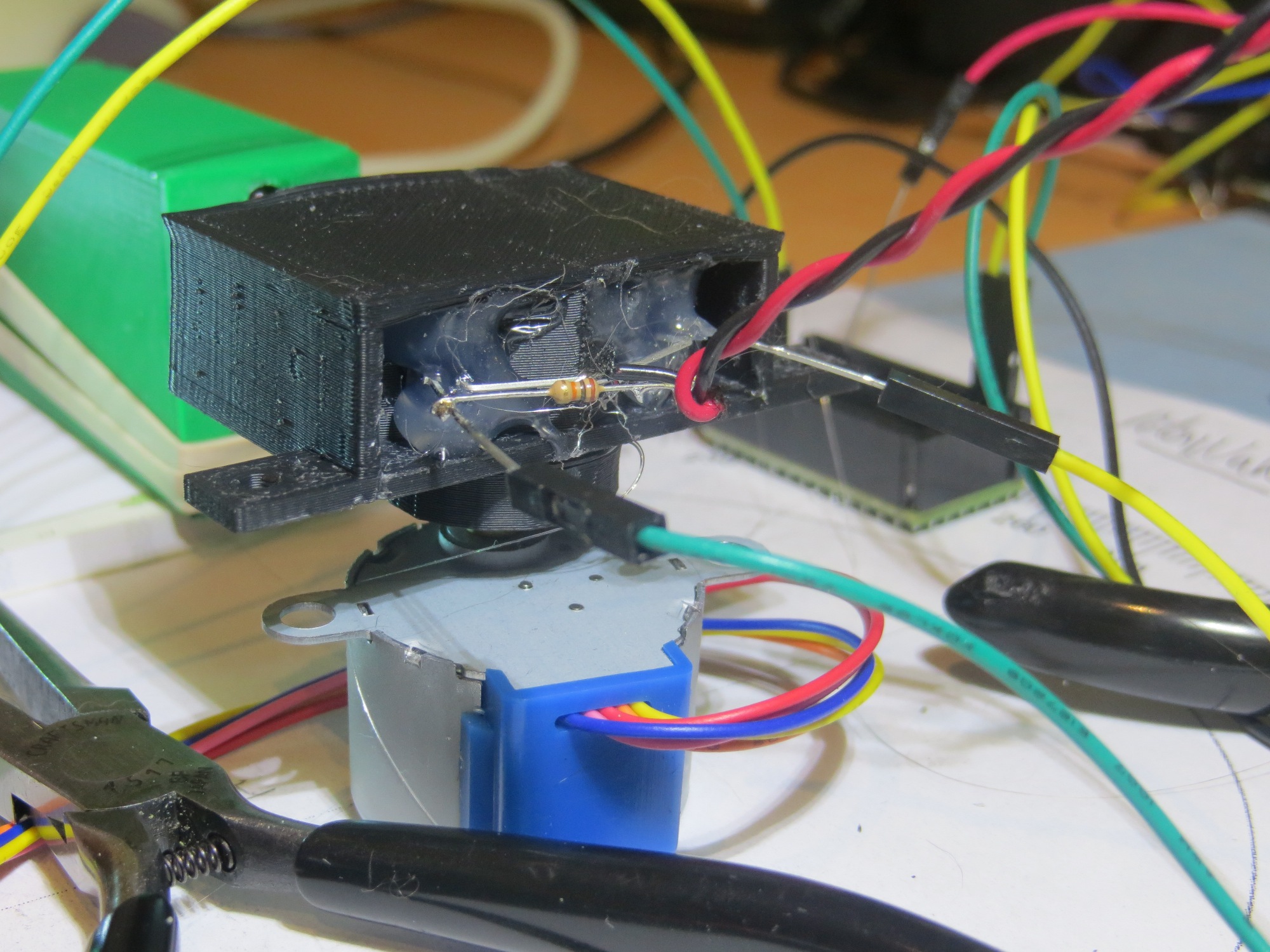
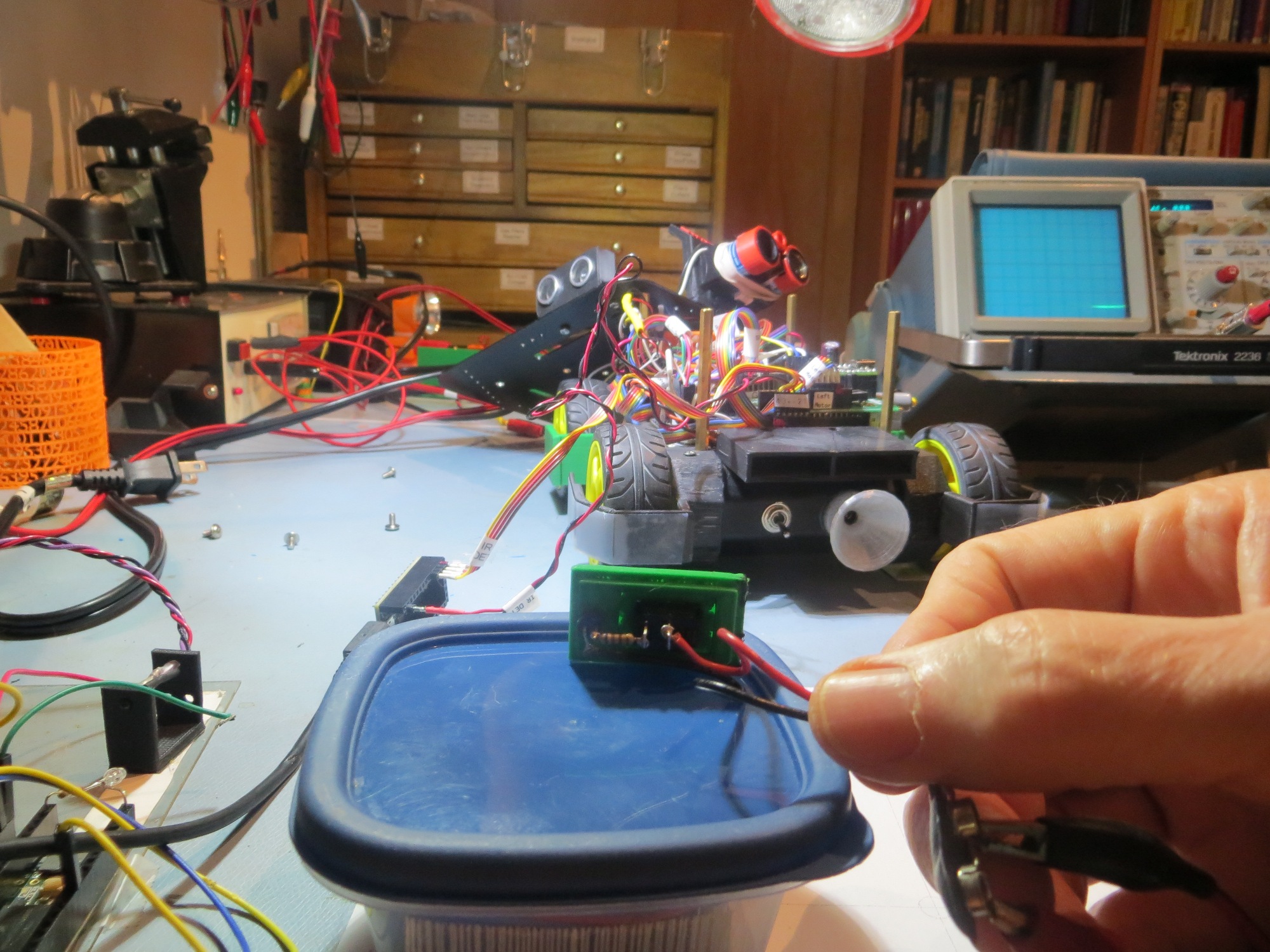
In the above video, The Teensy 3.5 SBC that I am moving around by hand is transmitting a square-wave modulated IR signal, which is being received by the detector module mounted to the rotary table.  The signal from the detector module is being fed to the Teensy 3.2 SBC in the far background, which decodes the modulated signal and generates real-time diff/sum steering values. The stepper motor controller module (the Teensy 3.2 in the near background) acquires these values about 5 times/sec via the I2C channel between the two Teensy’s, and uses this information to turn the stepper motor cw or ccw to track the moving beacon transmitter.

I’m probably not going to win any awards for smoothness and accuracy of tracking, but that’s not the point.  The point is that I now have implemented all of the components needed for a fully functional tracking system.  In the above video, the tracking system controls a cheap stepper motor to track a moving IR beacon, but in the intended application, the tracking system will control the robot’s wheel motors to home in on a stationary IR beacon.

Still lots to do, but at least I now know that I can make all the pieces work together once I get each piece optimized.

  1. Still need to finalize the IR detector part.  I’m now leaning toward the OSRAM SFH-314 +/- 40 º beamwidth phototransistor.
  2. Still need to finalize the collector resistor value for the detector.  Need a sufficiently low value to prevent detector saturation under worst-case (or nearly worst-case) conditions for the intended environment (not the thermonuclear warfare on Mars environment that my friend and mentor John Jenkins apparently recommends, but still stressful), but a sufficiently high value so that the IR beacon can be detected from far enough away (approx 2m) so the robot has a chance to engage the lead-in rails and mate with the charging connector.
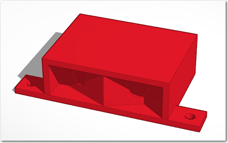
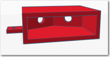
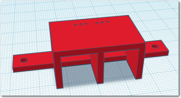
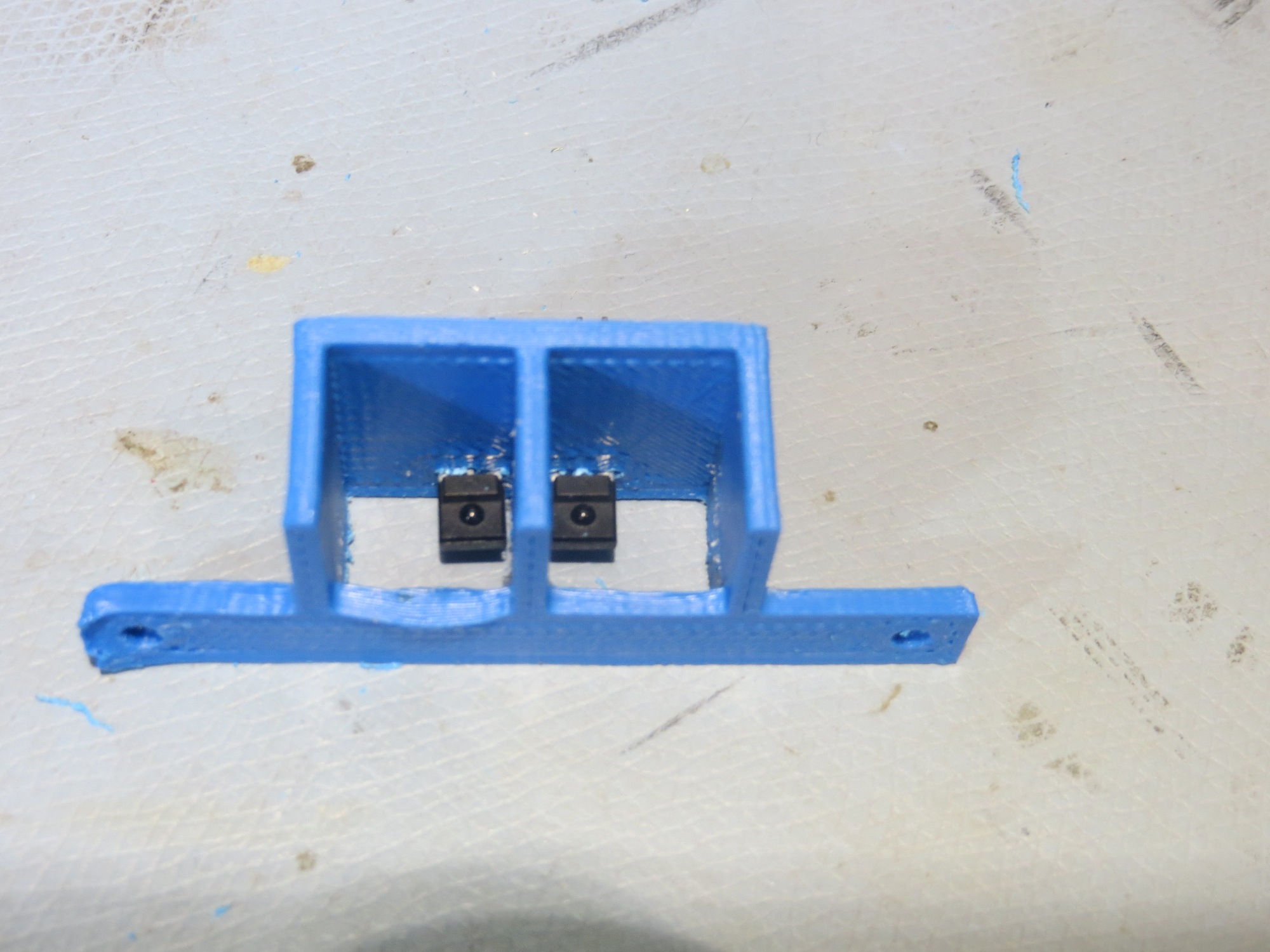
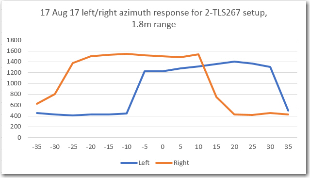
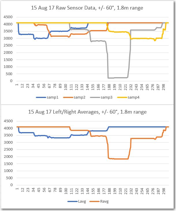
  3. Still need to finalize the sunshade configuration.  Currently it is a simple rectangular cylinder with the detectors angled away from the centerline.  There is some evidence in the azimuth scan data that the side walls are too close to each other, overly restricting the side-look angles of the detectors.  This issue may be further exacerbated when I go to the wider beamwidth SFH-314’s vs the SFH-300’s.  I may wind up with a sort of ‘squashed funnel’ shape in the end – but more testing is required to nail this down.
  4. And finally, I still need to get this all back on the robot and actually get it to work!

Stay tuned,

Frank


IR Homing Module Integration, Part IV

Posted 27 August 2017

After returning from our eclipse-watching trip to our kids’ place in St. Louis (the solar eclipse was awesome, by the way), I spent some time rethinking the IR detector problem.

In St. Louis I was struck by how easy it was to overload the TLS267 sensors with either ambient sunlight or overhead incandescent lighting.  The kitchen table where I was working had a hanging light with a halogen center bulb, and when that was on it immediately flooded the sensors, even with an ‘opaque’ sunshade; the only way I could get the sensors out of saturation was to hide it under an overturned coffee cup!

My friend and mentor John Jenkins’ solution for this was to add optical attenuation, such as a translucent film, but I wasn’t (and am not) sure this would work very well.  And besides, it bothers me to have to work  another problem (attenuator material selection, mechanical design, testing, etc) just to address a problem (too much gain, no gain control) with the TLS267 sensor part.

The TLS part is nice because it has a fairly wide beamwidth (so only 2 sensors are required) and its output is proportional to optical power density rather than inversely proportional like most phototransistors.  However, its gain isn’t adjustable at all – you take what you get – thus the need for optical attenuation.  Other parts, like the OSRAM  SFH 300 (+/- 25deg) or 314 FA (+/- 40deg) have nice beamwidths, and the gain is adjustable via collector resistor selection.

If I believe the 0.2mA direct sunlight value from the 17 May tests, then I can use a 12.5K resistor to achieve a 2.5V drop, leaving 0.8V Vce at 3.3V Vcc – therefore not quite saturating even in direct sunlight.
If I believe the 0.5mA at 0.5m distance, the above 12.5K resistor would produce about (0.5mA x 12.5K = 6.25V at 0.5m (well into saturation), and about 1/16 that or 6/16 = 0.375V at 2m distance (probably a bit more due to the gain of the reflector).  0.375V should be more than enough for detection thresholding.
Also, I believe I can partition the usage universe into two distinct segments, by deciding to  not  place a charging station anywhere near the direct sunlight areas of the house.   If I do that, then the problem separates into two non-overlapping simpler ones.   In the direct sunlight areas, the problem is to avoid false-positive charging station detections, and in the indirect/no sunlight areas, the problem is to detect and home in on charging stations, possibly in the presence of overhead incandescent lighting and/or indirect sunlight.
  • In the direct sunlight areas, the N-path filter completely solves the false positive problem, as the unmodulated sunlight signal won’t get through the filter, and I can allow the detectors to saturate without worrying about missing a charger station signal.
  • In the indirect/no sunlight areas, I can’t allow the detectors to saturate, but since the maximum available field strength (at least from sunlight) is much lower (well below 0.1mA if you believe the 17 May data), then higher gain should still be OK.
  • I plan to add some AGC capability by using multiple digital outputs to power the ptrans via multiple 12.5K resistors.   I can 3-state outputs to disconnect them from the circuit, or drive them to Vcc to connect them.   Each connected output would lower the gain.   Two active outputs  = 1/2 gain, 3 = 1/3, etc.   That should take care of saturation issues near the charging station.   The Teensy 3.2 has  lots  of digital outputs, so I could go wild along these lines if I wanted to ;-).

The above line of reasoning  did not meet with approval from John; in fact it would be safe to say that I have driven him nearly to apoplexy with my blatant disregard for data that doesn’t support my thinking.  Disregarding data is an absolute go-to-hell-and-burn-forever sin in John’s world (and in mine, to tell the truth), but I have a fair amount of confidence that the data he is referring to came out of a crappily-constructed experiment, while the data I am using to support my thinking came from a later much more rigorous one.  When I’m dealing with John, I try to keep in mind that he is right about 90% of the time, so I have to have a ‘Plan B’ in the likely case that I’m wrong.  In this particular case, ‘Plan B’  is simply to reduce the value of the collector resistor to the point where the sensor won’t saturate even in the face of my original crap-data experimental results.  In the meantime, I can continue to enjoy tweaking John ;-).

Since I had some OSRAM SFH-300FA (+/-25 º beamwidth) phototransistors hanging around, I decided to try them in a 2-detector setup using a 30 º angle offset as shown in the images below:

Rear view of SF300FA 2-detector mount design

Front view of SF300FA 2-detector mount design

Front view of SF300FA 2-detector mount

Rear view of SF300FA 2-detector mount

For the initial trial, I used 10KΩ collector resistors as a starting point, mainly because I have  lots of 10KΩ resistors, and zero 12.5KΩ ones.

When my grandson Danny and I were doing the azimuth scans of the TLS267 sensors in St. Louis, I realized that we needed lots more points than we were getting, if we were to have any hope of actually characterizing the azimuth response of the sensors, so I decided I was going to have to construct a computer-controlled azimuth scan turntable.  I had a couple of cheap 28BYJ-48 stepper motors with an ULN2003-based driver (shown below), so I thought I might be able to rig something up.

28BYJ-48 stepper motor with driver

Originally I had planned to integrate the turntable code directly into the IR Beacon Homing Module Arduino project, but I quickly realized this was a  bad idea.  Instead I created a new ‘RotaryScanner’ Arduino project to handle all the stepper motor related code, and then I created another Teensy-based project to actually perform the azimuth scan and record the results.  To run a scan, I initialize the scan parameters (speed, start/stop angles, etc) using the RotaryScanner project, and trigger the scan from the recorder project.  This way I get an azimuth scan where I know the start & stop angles associated with the data, and so I can interpolate the azimuth position for each datapoint – neat!

When I was finished with this little side project, I had a Uno-based RotaryScanner module interfaced to the stepper motor driver, and a Teensy-based recorder module to capture the sensor data.  I also printed up a small turntable to adapt the sensor ‘sunshade’ module to the stepper motor shaft, proving once again how handy it is to have a 3D printer in my lab ;-).  The entire arrangement is shown below, and I have included a short movie of the system in action.

IR sensor azimuth scan setup. Uno stepper motor controller and motor driver are in the foreground, Teensy recorder module in the background. The IR sensor module is hot-glued to an adaptor disk, which mates with the stepper motor shaft. The stepper motor base is hot-glued to my compass rose sheet.  The green box is my portable IR test source.

After getting everything set up and running, I collected an azimuth response data set using my portable IR source (the green box), with the results shown below

OSRAM SFH300FA phototransistors in a 30-deg offset arrangement, no center divider

The horizontal axis values aren’t necessarily exact, as they are interpolated from the known starting and ending values, but they should be pretty close.  As can be seen, there is pretty decent symmetry between the two responses.  Unfortunately, both sensors saturated near their respective peaks. Here’s another plot with a slower rotation speed (more data points per degree), and with the IR source back a bit to get out of the saturation region

And here is a plot of the (Det1-Det2)/(Det1+Det2) steering function.  From this plot, it appears that good steering information is availabale from about -27 º to about +36 º or about 63 º total.  this might be a little narrow for the intended application, so the OSRAM S  Stay tuned!

(Det1-Det2)/(Det1+Det2)

30 Aug 2017 Update:

I ran a couple more azimuth scans tonight, just playing verifying that I could get both forward and reverse scans to work.

More detailed azimuth plot, using 2e OSRAM SFH-300s with Rc = 10k

Forward and reverse azimuth plot, using 2e OSRAM SFH-300s with Rc = 10k

The next goal is to modify my Uno-based rotary scanner program to act as an IR source tracker, turning the stepper motor to keep the detectors aligned with an IR source.   In the real robot,  the detector module will be fixed, and the the wheel motor speeds will be adjusted to center the entire robot on the IR source.  However, I believe I can test out the algorithm without having to fully integrate the module onto the robot.   Stay tuned!

Frank


IR Homing Module Integration, Part III

Posted 20 August 2017

I’m writing this post from our Kids’ place in St. Louis, which just happens to be in the path of totality for the upcoming solar eclipse.  As usual, I brought my project stuff with me so I can work in the off moments, but this trip has a bonus in that I have managed to suck my 14 year-old grandson Danny into helping me with the robot project.  He also has my old PrintrBot ‘Simple Metal’ 3D printer, so he is able to print up new IR detector holders as required.

So, the first thing we did was to print up a new holder with a 30 º angular offset for the detectors; this is something I forgot to do with the previous model.  With this setup, we got the following results from an azimuth scan.

Azimuth scan for 2-detector model with 30-deg angular offset and center divider

meanwhile, my friend and mentor John Jenkins came up with a set of simulated azimuth response curves (shown below) that showed that the center divider (apparently originally intended to make steering more responsive) was more of a liability than an asset.  Turns out (at least according to John’s results) that removing the divider makes the (diff/sum) ratio curve smoother and more linear in the critical boresight region.

Loader Loading...
EAD Logo Taking too long?

Reload Reload document
| Open Open in new tab

Download

So, we printed up a new holder with the center divider removed (and in the process made the walls thicker to block IR transmission through the material), and took some more measurements.


IR Homing Module Integration, Part II

Posted 17 August 2017

In my last post on this subject, I noted that the output from one of the four IR LEDs used in the current arrangement was considerably larger than from the others (like  several times  larger).  This was a bit disturbing, to say the least, as proper homing operation depends in large part on having consistent responses from all four sensors.  After some troubleshooting, I came to the conclusion that the culprit here is the narrow beamwidth of the SFH-309FA IR phototransistors  I am using.  I originally chose this unit for it’s narrow beamwidth as a replacement for the IR photodiodes in the OSEPP IR Follower module (see this post).  This setup seemed to work OK, but as I developed the ‘sunshade’ addition to suppress unwanted interference from sunlight and overhead incandescent lighting, and the reflector idea for the charging station, I think I inadvertently exacerbated the effect of narrow beamwidth in the vertical dimension.  When the now-narrower transmit beam is well-aligned with the narrow receive beamwidth of a particular phototransistor, the response can be several times higher than when they are not aligned.  A further complication is that just statically aligning the transmitter beam with the receiver beam may not be sufficient, as there may be some physical misalignment of the charging station with the robot as the robot approaches.

Independently of the above, a lot of water has flowed over the dam in the ten months since the original implementation of the 4-element phototransistor array.  Most importantly, in collaboration with my friend and mentor John Jenkins, I have successfully implemented a two-channel ‘degenerate N-path band-pass filter’ to allow for discrimination between unwanted IR interference and the desired charging station IR beacon.  Now the homing beacon will be modulated by a 520Hz squarewave, the center frequency of the BPF.  For this implementation, only two IR detectors are needed, rather than the four that I currently have.   In my initial attempt at integrating the new BPF capability into the robot, I simply averaged the two left and the two right phototransistor outputs to simulate a two-element setup, but as noted above this ran into problems due to the narrow vertical beamwidths of the SF309FA devices.

Rather than try and get all four phototransistors aligned with each other and with the charging station transmit beam, I decided to punt on the entire 4-element array design and start over again, using two detectors with wider beamwidths and a sunshade with a center divider, as shown below:

2-detector sunshade for use with TSL267 IR-to-voltage devices

2-detector sunshade, top view showing interior and exterior angles

In the above screenshot, the green plates represent the TSL267 beamwidths, as modified by the walls of the sunshade.  The front-to-back dimension of the sunshade was set to allow a 30 º exterior beamwidth, and the location of the device with respect to the center divider was set to allow a 10 º overlap between left and right detectors.  These values were somewhat arbitrary, but I think they represent a good starting point.

After a couple of false starts, I got a decent sunshade printed out, and mounted two TSL267s.  Then I connected them to my Teensy 3.2 and ran an azimuth using my 1.8m range, as shown in the photos below.

Front view of new sunshade, with two TSL267s installed

Sunshade with 267s installed and connected to Teensy 3.2 for azimuth testing. Note ‘sta-strap’ pointer

1.8m range. Note charging station in background (orange assembly just to left of 3D printer) with IR LED at center of reflector

As shown below, the azimuth response is pretty close to the predicted values – about 35 º either side of boresight, with about 10-20 º overlap between the left and right responses.  A nice benefit of switching to the TLS267 is the internal inverting op-amp, which produces an output with the same sign as the received field intensity.  This will require a few modifications to the IR demodulation algorithm, but well worth the minor trouble.

Azimuth response for 2-TLS267s installed in sunshade

Looking at the above plot, I’m not sure that the overlap region is narrow enough for good tracking.  If I understand the dynamics correctly, the two channels will show the same demodulated value for +/- 15 º, so the system won’t know to correct within this range.  I’m thinking I would like to have this be more like +/- 5-10 º maximum.  So, I will print another version of the sunshade with a 10mm longer front-back dimension and see how it works.

Stay tuned!

Frank


IR Homing Module Integration, Part I

Posted 06 August 2017

Now that I have the 2-channel IR demod algorithm working, it’s time to start integrating the capability back into my long-neglected Wall-E2 robot.  The grand plan here is to incorporate the IR demod algorithm into a ‘IR Homing Module’ with raw IR sensor input on one end, and (R-L)/(R+L) normalized steering information output on the other, as shown in the following diagram.

Teensy 3.2-based IR Demod module block diagram


As the first step in this project, I wanted to verify that I can port the IR demod algorithm from its current Teensy 3.5 SBC host to a Teensy 3.2.  The Teensy 3.2 is about half the size of the 3.5, runs at 72MHz instead of 120MHz, and has “only” 64KB RAM instead of the 3.5’s 192KB.  I didn’t think any of this would matter, but you never know ;-).  The code modifications required to run this test were pretty trivial; I had to comment out the DAC1 setup lines, and change the pin number for the Channel 1 DAC0 output from A21 to A14.  Then I commented out the lines that transmitted the Ch2 final value to the now-nonexistent DAC1 port and that was it.  The following photo shows the T3.2 in the foreground, with the T3.5 sweep generator next back, and the original T3.5-based IR demod host in the background

Teensy 3.2 trial as host for IR demod algorithm. The Teensy 3.5 in the middle is the sweep generator and the one in the back is the original host for the 2-channel IR demod algorithm

After making the above changes, I ran a frequency sweep from 510 to 530Hz in 0.1Hz steps, 0.5S/step, with the following results.

Frequency sweep of the IR demod algorithm hosted on a Teensy 3.2

For comparison, here is the same plot from the previous post using the Teensy 3.5.

I think it’s safe to say that the Teensy 3.2 operating at 72Mhz is doing as good a job with this algorithm as the Teensy 3.5.

So, the next step was to figure out how to get the steering information from the Teensy to the main robot controller (a Mega 2560).  I decided to use the I2C port for this purpose; the Mega has one I2C port, and the Teensy has several, so this should work.  Of course that means I have to figure out how to actually  use the I2C capability, but hey – that’s what the internet is for ;-).

In any case, I found the new  i2c_t3 library for use with Teensy 3.x, and the ‘I2C_Anything’ library for transparently handling arbitrary data types, and a couple of examples showing their use.  With these (and my handy-dandy Teensy testbed) I was able to implement a little master/slave demo project to confirm that I could use I2C to transmit float data values from the Teensy 3.2 I would be using as the IR homing beacon demodulator to the Mega.


Output from master/slave demo project

So the next step is to integrate the above master/slave I2C code into the Mega 2560 and the Teensy 3.2.  The plan is to have the Mega request data from the Teensy, and the Teensy will then transmit the latest L/R steering value.  There will be no buffering on either end, so whatever the Mega doesn’t request will simply fall off the end into the ‘bit bucket’.

Currently, the IR phototransistors appear on pins 55-58 (A1-A4) on the Mega.  These will be transplanted to pins 14-17 on the T3.2 (A0-A3).  GND will go to GND, and +5V from the Mega will go to ‘VIN’ (+5V with USB connected) on the T3.2.  With this setup, and a few modifications to the ‘Master’ sketch in my previous master/slave demo program, I should be able to transmit a 520Hz square-wave modulated IR signal to the IR detectors, and have it appear on the master’s serial port after having been demodulated by the T3.2 – stay tuned! 😉

As an interim step, I disconnected the four IR sensor leads from the Mega 2560 and reconnected them to the T3.2, as shown below.


IR sensor connections moved to the Teensy 3.2 IR Homing Module

Next I set up an IR LED source a few inches away from the detector array and moved it from right to left across the array field of view, and recorded the raw sensor data as received by the Teensy, as shown below:

Raw IR sensor data as received by the Teensy 3.2

Left & Right averages

So, the IR sensors are indeed alive (maybe  too alive in the case of sensor #3) and working, and the A0-A3 analog inputs are verified working as well.  Also, in this very rough test, it is apparent that the responses from all four sensor overlap to form a continuous field of view, and that averaging the two left and two right IR sensor data sets also works.

Next, I moved the range out to 1m and then to 1.8m and ran the same tests, with results as follows:

From the above results it is clear that sensor #3 is considerably more sensitive than the others.


IR Modulation Processing Algorithm Development. Part XVII

Posted 30 July 2017

This long-running saga started actually started almost exactly two months ago with the weekend visit of my friend and long-time mentor John Jenkins.  Naturally, being fellow geeks, I showed him all my new toys, including Wall-E2, my autonomous wall-following robot.  When I explained that Wall-E2 was having some trouble homing in on an IR beacon to connect to a charging station due to the ‘flooding’ effect of direct sunlight and overhead incandescent lighting (see for instance, this post), John opined that the way to address this problem was to modulate the homing beacon with a square wave, and then use a  ‘simple’ digital filter on the robot to better discriminate between the wanted (square-wave modulated) and unwanted (sunlight and/or incandescent lighting) sources.

Right then and there I should have realized I was in trouble, because I have (or should have!) learned over the years that whenever John uses the word ‘simple’, what he really means is “this is going to be so complex that you will wish you never listened to me”, and what he means by the word ‘better’ is “this will make your robot capable of operating from the vacuum of space to the depths of the ocean, in the middle of a thermonuclear war.  All other life on earth will have long since been reduced to its constituent atoms before your robot fails to meet spec”.  What I should have done was say to John “that’s nice John, but I think I’ll just operate Wall-E2 at night with the lights off”

But noooo, I fell for this line, (again!), and said “hmm, sounds interesting John”, thus going down yet another rabbit hole in my quest to make Wall-E2 completely autonomous. So now I started working on the design and implementation of a ‘degenerate N-path band pass filter’ (John’s term), a project tangential to the implementation of a charging station, which in itself was tangential to my original wall-following robot project.  My only justification (well justifications) for this clearly insane behavior are:

  1. I  am clearly insane – I’m a twice-retired engineer, after all!
  2. The entire impetus for the Wall-E2 project was to give me a way to waste as much time as possible in an intellectually stimulating way, and the idea of implementing a ‘degenerate N-path band pass filter’ promised to waste a lot of time (and besides, being able to tell people I had implemented a “degenerate N-path band pass filter”  was just too sexy to pass up!)

Well, it has been a heck of a journey these last two months, but I believe that with John’s help (or possibly in spite of it), we now have a working two-channel 520Hz N-path BPF,  and as a bonus – a working high-accuracy frequency/amplitude sweep generator, both based on Paul Stoffregen’s wonderful Arduino-ish Teensy 3.5 SBC.  The last piece of the puzzle for the sweep generator design fell into place just yesterday with a post from ‘tni’ on the Teensy user forum, describing the proper technique for updating the count-down value for the Periodic Interrupt Timer (PIT) used in the sweep generator.

Sweep generator recap:

The original plan for the sweep generator was to use the same ‘elapsedMicros’ object type that I had used to generate the transmit waveform, but it turned out (see this post) that t he ‘elapsedMicros’ technique produced an unavoidable frequency offset.  So, searching for other alternatives, I tried a rounding technique using ‘elapsedMicros’ which helped somewhat but didn’t really solve the problem, and then a method using Daniel Gilbert’s IntervalTimer library (this library wraps access to the Periodic Interrupt Timer (PIT) module of the FreeScale Cortex-M4 microcontoller used in the Teensy 3.x line).  This technique produced a very accurate frequency output, but unfortunately also produced bad artifacts in the frequency response curves from the N-path BPF implementation due to the delays inherent in the need to stop and then restart the PIT for each new frequency step.  A representative ‘raw’ and ’round-trip’ frequency response curve set is shown below to illustrate the problem, along with the timestamp representation of the PIT operation.

‘Round-trip’ and ‘raw’ FinalValue vs Frequency, with IntervalTimer technique

Square-wave transition times vs time using the IntervalTimer technique

I was just about ready to give up on the IntervalTimer technique, and just deal with the frequency offset inherent in the ‘elapsedMicros’ technique. However, John shamed me into putting a post up on the Teensy forum explaining my issues and asking for help.  I hate to say it but I’m glad he did, as among the other helpful posts was one from ‘tni’ with the complete code for an add-on function to the IntervalTimer library to do just what I wanted – update the count-down count in the PIT without disturbing anything else.  As a result of this addition, I was able to get frequency-accurate response curves from the IR demodulator filter without any ugly artifacts, as shown below

‘Round-trip’ and ‘raw’ FinalValue vs Frequency, with IntervalTimer technique, using tni’s updateInterval() function

Square-wave transition times vs time using the IntervalTimer technique, using tni’s updateInterval() function

So now I have a sweep generator that works – albeit one that needs a little cleanup before I push it up to GitHub

August 02 2017 Update:

Today I finally ‘finished’ (to the extent that I ever really finish anything) the 2-channel IR demodulator algorithm, and the accompanying frequency/amplitude sweep generator, and posted both to my GitHub account (see  https://github.com/paynterf/SqWaveIQDemodV2 and  https://github.com/paynterf/TeensySweepGen).  After squashing a few last buglets, I was able to run fairly detailed frequency sweeps on both demodulator channels using the sweep generator, with the following results

If you like data, this is pretty good stuff – nice and smooth, no unusual artifacts, nicely centered around 520-522Hz, and the Ch1/Ch2 overlap is almost perfect.  Whatever else has happened in this little 2-month vacation from reality, the ‘N-path band pass filter’ algorithm clearly works, at least on the bench.

Now that I have the BPF algorithm humming along, the next challenge will be to integrate the BPF module onto the robot, and modify the charging station to modulate the IR homing beacon with the requisite 520Hz square wave, and of course test it all to verify functionality.  Still plenty of work to do, so I don’t have to worry about getting bored anytime soon!  Stay tuned…

Frank