Posted 16 May 2017
One of the suggestions John Jenkins made during his visit, in addition to the idea of modulating the IR beam to suppress ‘flooding’ from ambient IR sources, was the idea of placing an opaque divider between the left and right halves of the detector array. He thought that I might even be able to reduced the detector array from four to two phototransistors and still get good homing performance, assuming that each of the two detectors had sufficiently wide beamwidths to accommodate off-axis IR beam intercepts. The current detectors have a +/- 12 º beamwidth, but are arrayed in such a way as to provide well over 60 º aggregate coverage. To do the same thing with just two detectors would require parts with considerably wider beamwidths. the TAOS TSL267 (another one of JJ’s suggestions) has an approximately +/-30 º beamwidth at the half-response points, so they seem almost ideally suited for this application. As a major added bonus, the TAOS parts feature a photo-diode integrated with an op-amp to address the dynamic range issue mentioned by John. The diode operates in its linear range, and the op-amp amplifies the IR signal to useful levels. The only fly in the ointment is that the op-amp gain isn’t adjustable, and its output limits at fairly low light levels – bummer!
 Loading...
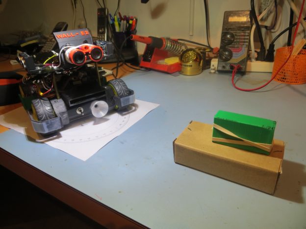
In order to investigate the opaque divider idea, I decided to run some bench angular response tests using my robot’s 4-detector array with and without a center divider. I printed out a copy of the compass rose graphic I had hanging around from my magnetometer project (one of my more spectacular failures) and set up a bench test with Wall-E2 and my little IR test source, as shown below.

Angular response test setup
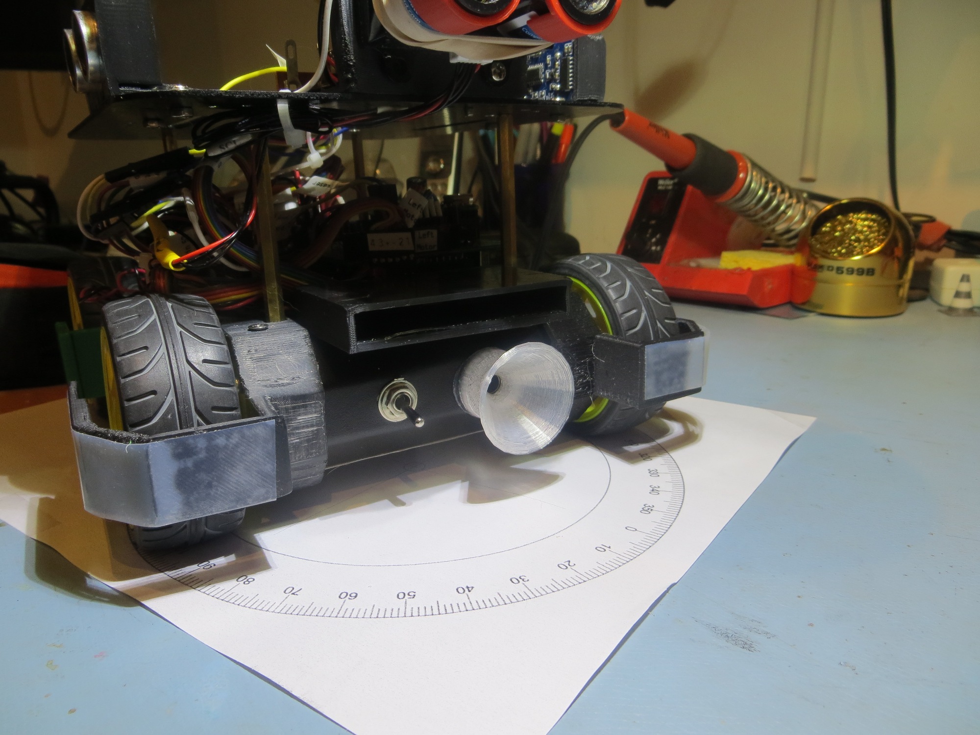
Closeup of the ‘sunshade’ cowling (black rectangular opening) around the 4-detector array
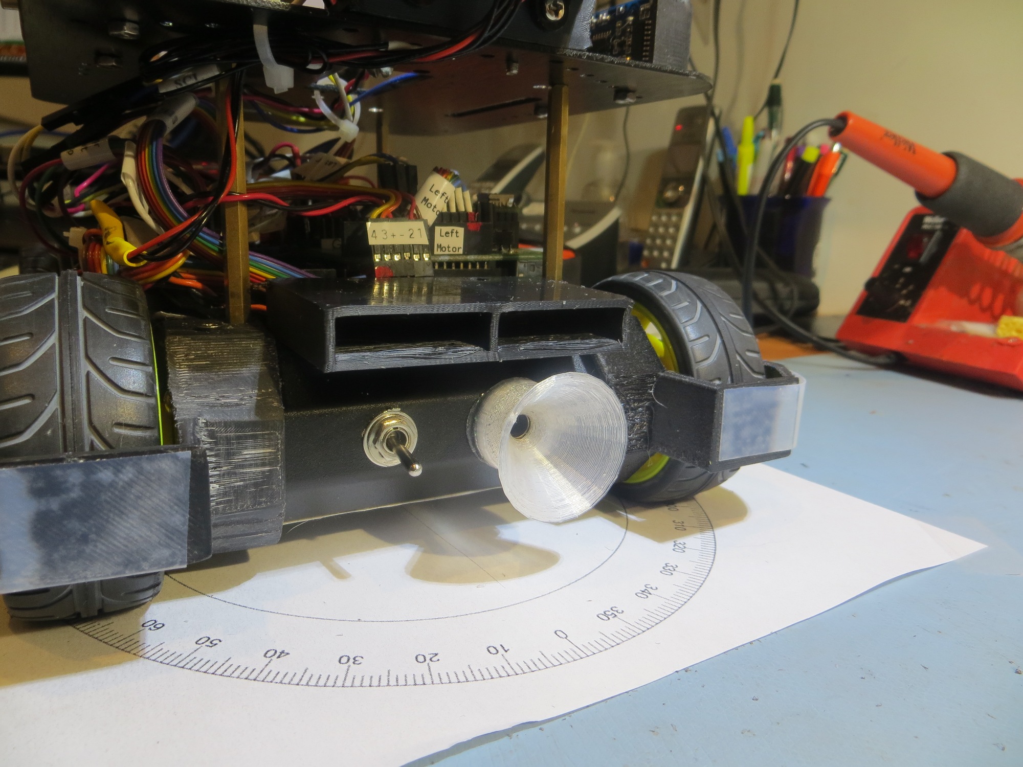
Closeup of sunshade with divider installed
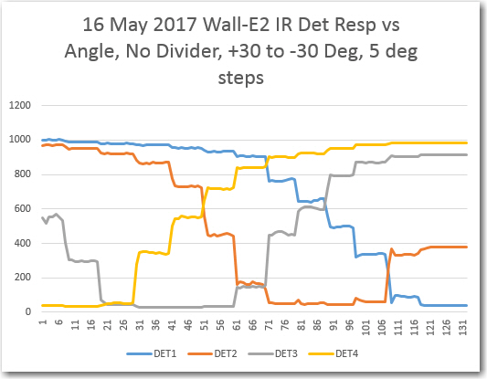
The results without the center divider were about as expected, with about +/- 45 º coverage, as shown in the Excel plot below
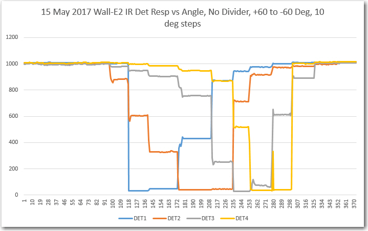
Response vs angle for 4-detector array, without center divider
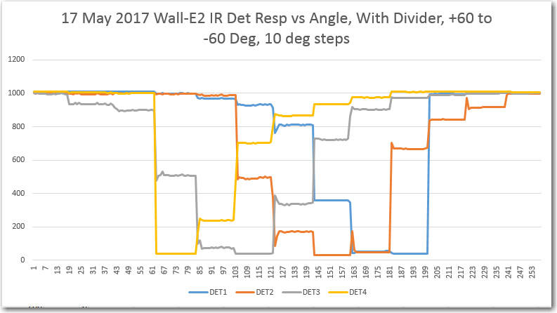
+/- 60 deg response vs angle for 4-detector array, without center divider
With the divider, the response appears to be about the same (note here that the ‘with divider’ response is flipped left/right from the ‘no divider’ case – oops!)
+/- 30 deg response vs angle for 4-detector array, without center divider
Note in the above ‘detail’ view that the response curves for the two center detectors (DET2 & DET3) seem to be very symmetric about the 0 º point, as expected. What this also shows is that just these two detectors could probably be used for homing, if off-axis beam detection weren’t a consideration.
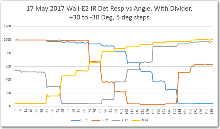
+/- 30 deg response vs angle for 4-detector array, with center divider
The ‘with divider’ plot above shows a significant difference from the ‘no divider’ plot, right at the center. In the ‘no divider case, the DET1 & DET2 responses are very nearly the same, but in the ‘with divider’ case they are significantly different, and almost perfectly anti-symmetric about the center. This should allow more precise detection of small left/right deviations from the beam centerline, and therefore more precise homing.
Stay tuned!
Frank