Posted May 10, 2017
A couple of weeks ago my old friend and mentor John Jenkins was visiting the area and stopped in for a couple of days. Naturally I had to show him my Wall-E2 robot, complete with autonomous charging capability. Just as naturally (if you believe in Murphy’s law), Wall-E2 refused to cooperate. Instead of homing in on the charging station, it blissfully homed in on the sunlight streaming in through the atrium, bypassing the charging station entirely!
After John got through laughing, he mentioned that he knew of some other IR-following robotics projects where the designers used a modulated IR beam to allow the robot to discriminate between general IR background noise and the intended signal. So, I decided to start a feasibility study to see if I could incorporate some sort of modulation into the design of the charging station, without completely overtaxing either the charging station, or the robot, or both!
I started with the idea that I could easily add square wave modulation to the IR beam by simply switching the LED off & on at some reasonable rate (say, 500Hz). The problem occurs on the other end (the robot), as it will somehow have to a) detect the square wave signal, and b) still have the ability to home in on the modulated signal – i.e. still be able to determine signal variation across the four photo-transistor array.
To investigate, I created a square wave generator using an Adafruit Trinket, and a square wave receiver using an Arduino Uno, as shown in the following photo
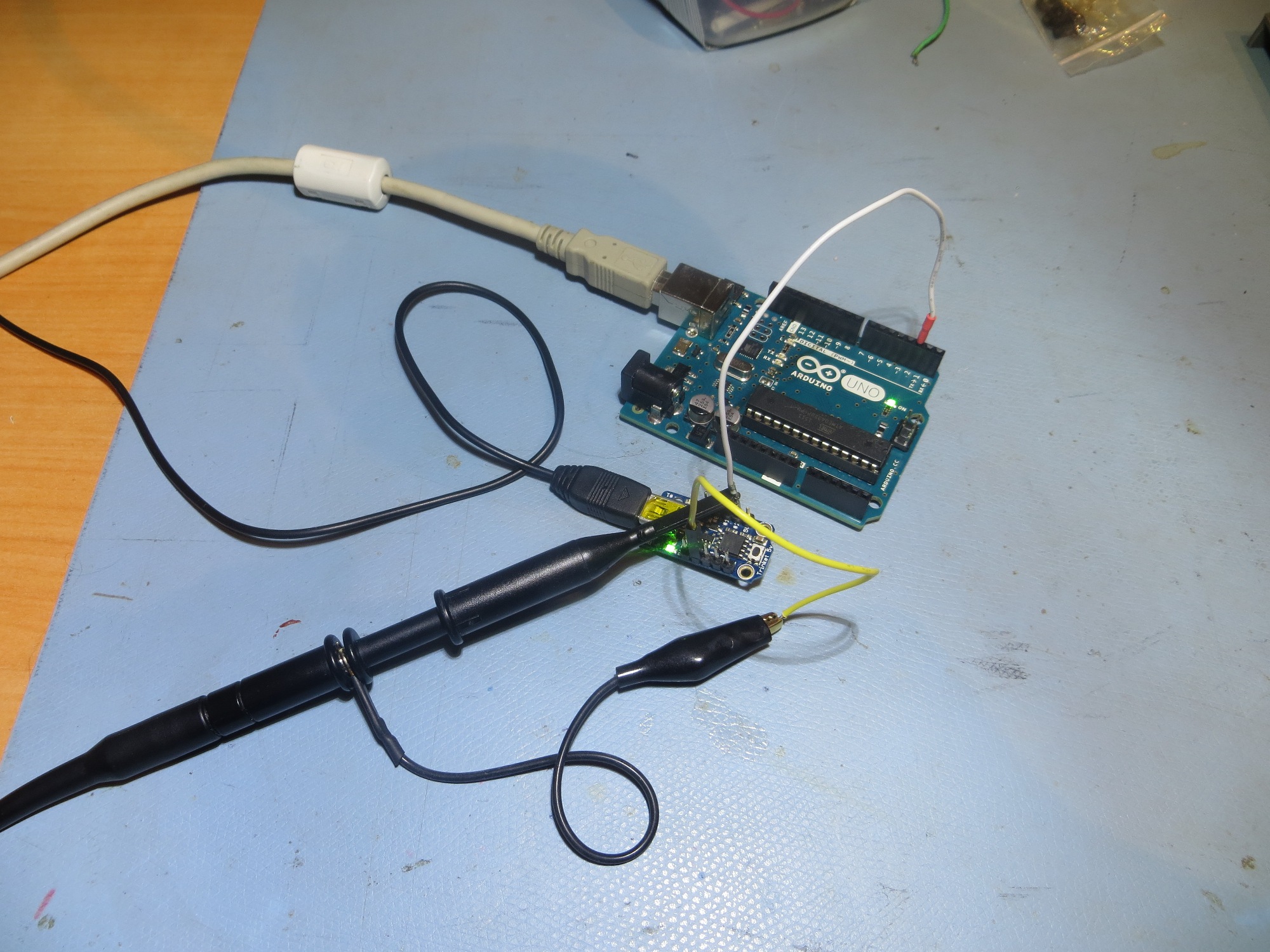
Adafruit Trinket SBC used for generating the square wave signal, and an Arduino UNO used as the receiver
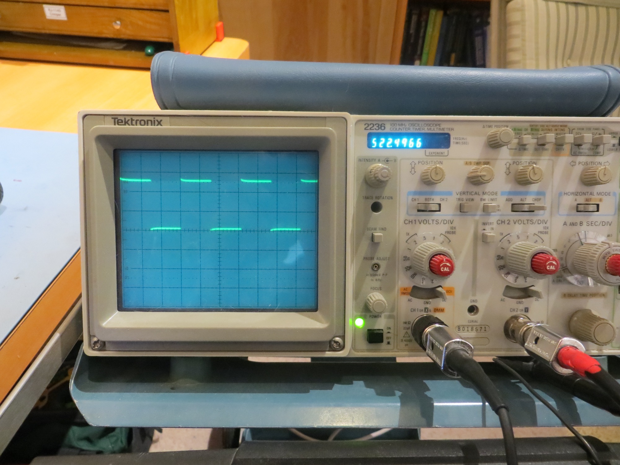
Square wave signal from the Trinket
The first step was to see if the Arduino Uno was fast enough to accurately detect the square wave pattern, so I simply grabbed 100 samples from the input pin using digitalRead() with a delay of about 1/10 of the waveform period. Then I plotted the data in Excel, as shown below:
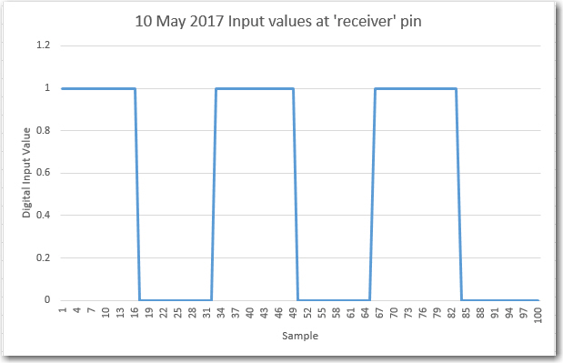
Digital samples from Arduino Uno ‘receiver’
As can be seen from the plot, there are plenty of samples per cycle, well above the Nyquist rate for the dominant signal term.
Next, I moved the square wave signal to an analog input on the Uno, and reprogrammed to collect analog values vice digital ones, as shown below:
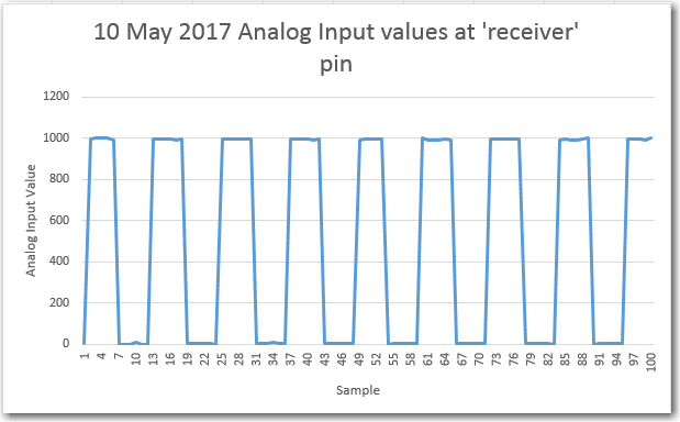
Analog readings with 500Hz square wave input
As can be seen, the analogRead() function is plenty fast enough to accurately reproduce the digital square wave signal, with about 10-13 samples/cycle. So, at least in principle I should be able to detect a square-wave-modulated IR beam, and determine its ‘field strength’ (analog reading when the beam is ON) for homing purposes.
Stay tuned!
Frank
Pingback: IR Phototransistor Sensitivity/Dynamic Range Study - Paynter's Palace
Pingback: IR Homing Module Integration Part X - Paynter's Palace