
Posted 07 April 2017
After getting the wall-following mode re-implemented in the ‘new-improved’ Wall-E2 operating system, I re-enabled the IR homing part of the code, only to discover that Wall-E2 thought it could see the IR homing beam everywhere, in the atrium, even though the IR homing LED wasn’t even in the room (and was turned OFF, besides)! This didn’t make a whole lot of sense, until I realized Wall-E2’s sensors were ‘seeing’ IR from the overhead floodlamps. I confirmed this by having my ‘lovely assistant’ wife turn the atrium lights on & off and monitoring the detector outputs. Same thing for the entry hallway (see data below)
I thought I had solved this problem way back when I first started working with the IR detection/homing idea back in October of last year. In that initial post where I investigated the OSEPP IR Light Follower’, I found I had to turn OFF the LED track lights in my lab in order to avoid swamping the detector array. Over the next month or so this project evolved into a custom designed array of Oshram SFH309FA-4 phototransistors (see http://gfpbridge.com/2016/11/ir-light-follower-wall-e2-part-vi/), and as part of this I discovered that the Oshram devices weren’t at all sensitive to the LED track lighting in my lab. From this I concluded (erroneously as it now turns out!) that I didn’t need a ‘sunshade’ at all, which allowed for a much simpler installation on the robot (see http://gfpbridge.com/2016/11/ir-light-follower-wall-e2-part-vii/). Finally, when this module was transferred from the 3-wheel test bed to the Wall-E2 and combined with the charging status display panel, we arrived at the ‘final’ arrangement shown in the following photo
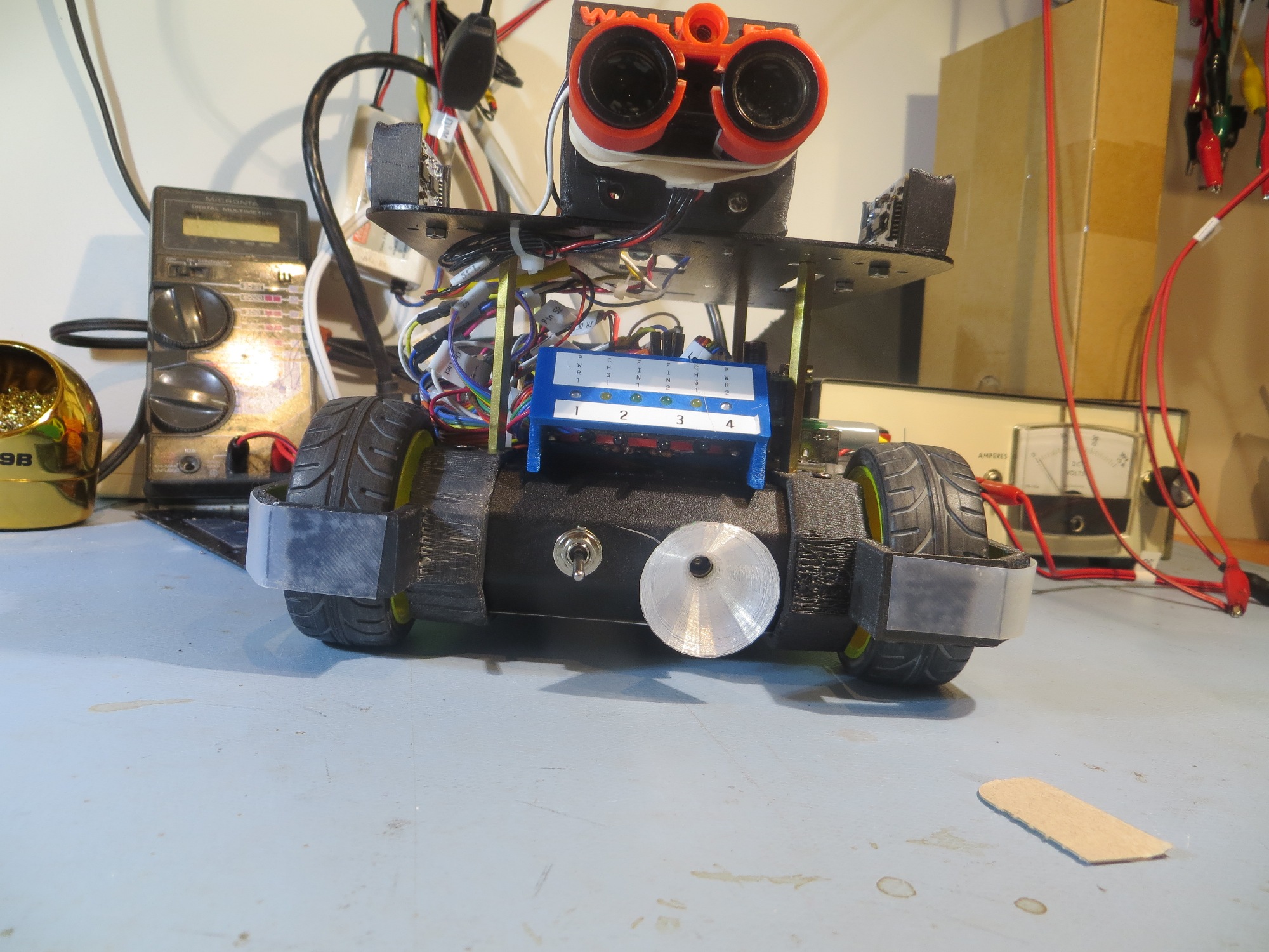
IR detector module (red) shown beneath charging status display panel (blue)
This worked great for all my in-lab IR homing tests with my all-LED overhead track lighting, but as soon as I started testing out in the rest of the house, the overhead incandescent and halogen lamps swamped out the detectors. So, it was back to the drawing board – again :-(.
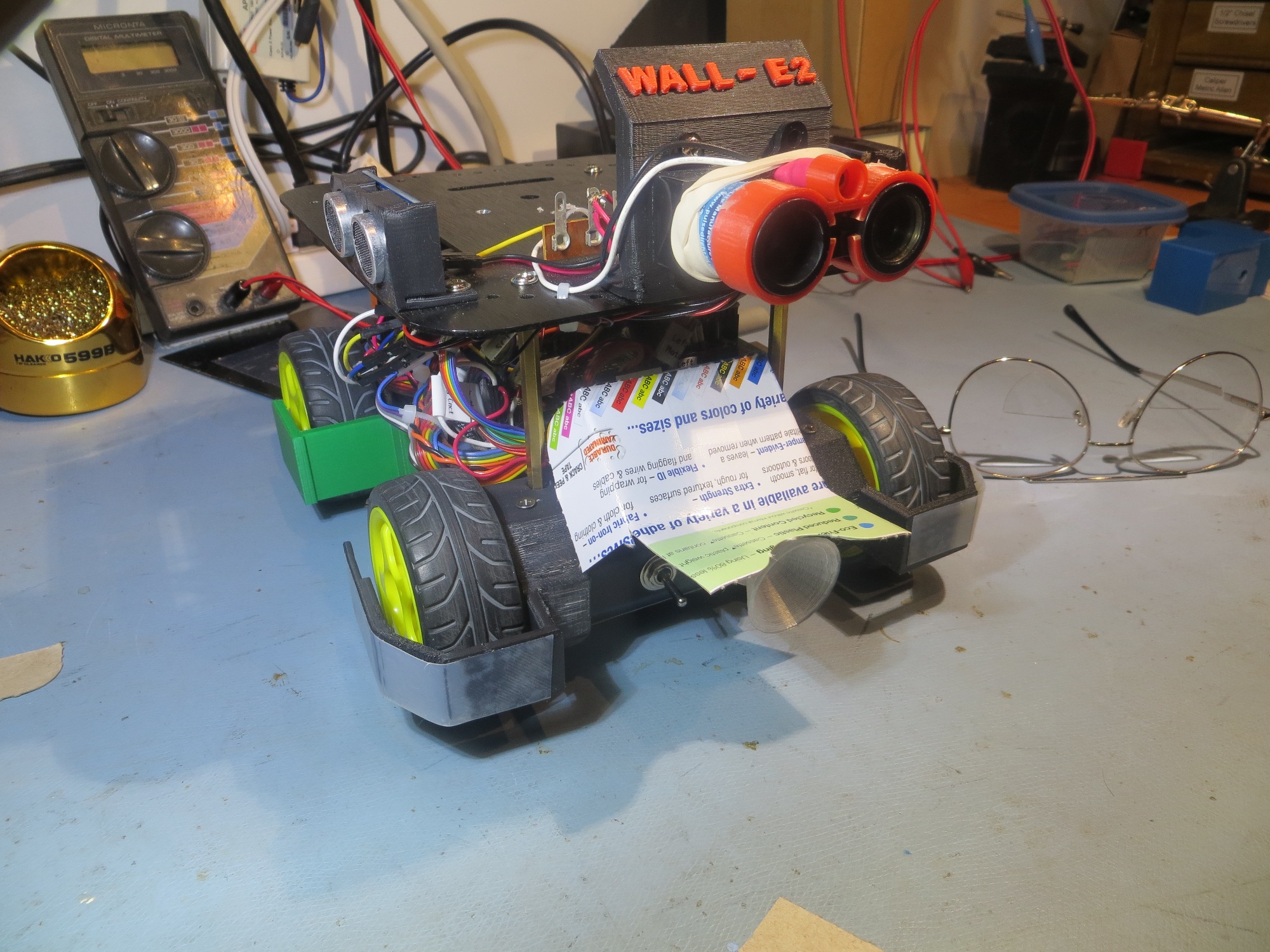
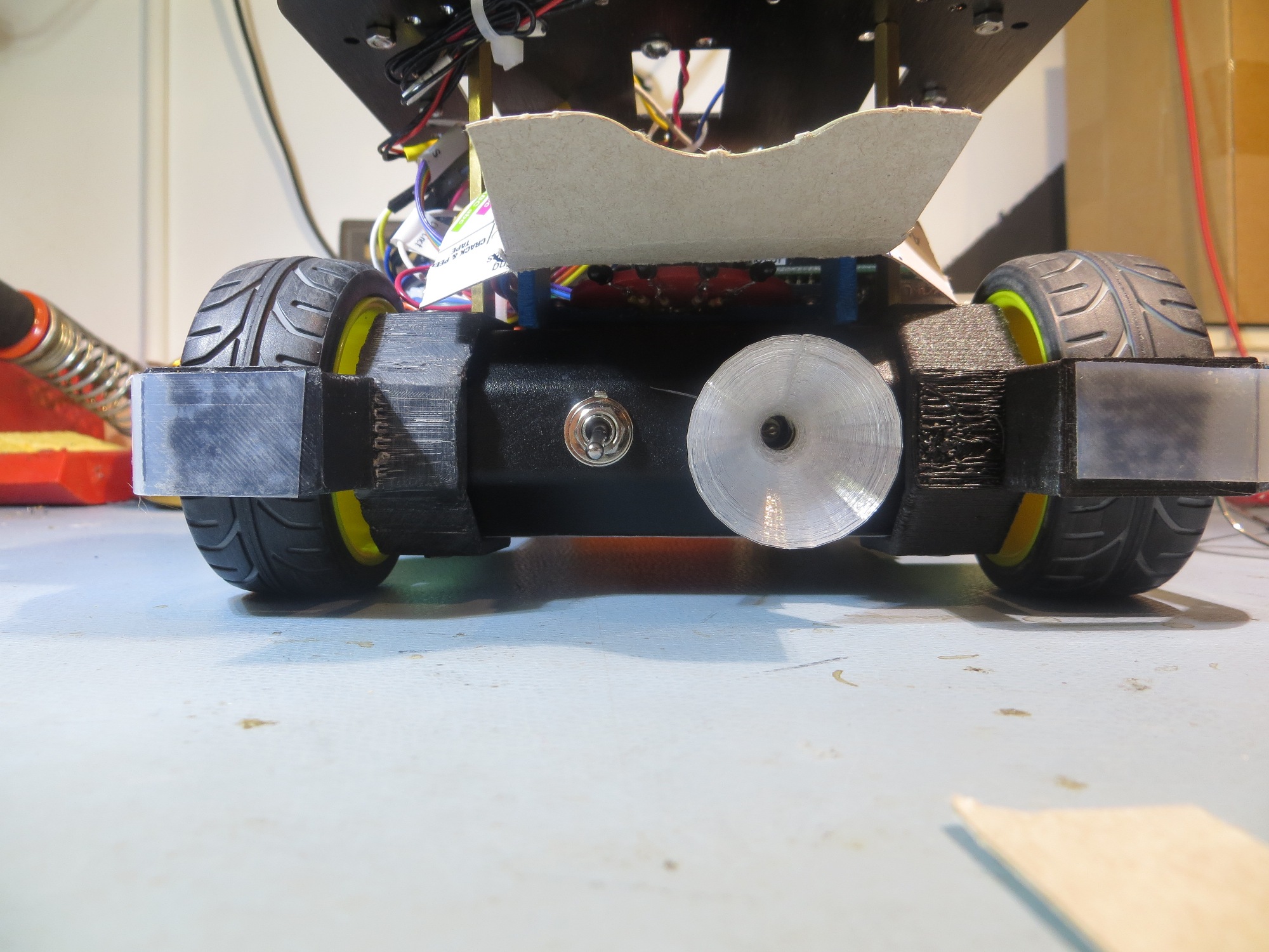
The first thing I did was to confirm that the IR detectors were indeed getting swamped by the overhead lighting, and that it was possible to prevent this by some sort of shielding. I started with a wrap-around cardboard shield that completely covered the IR detector module, as shown below, and placed the robot on the floor of the entry hallway in a normal ‘wall-following’ position
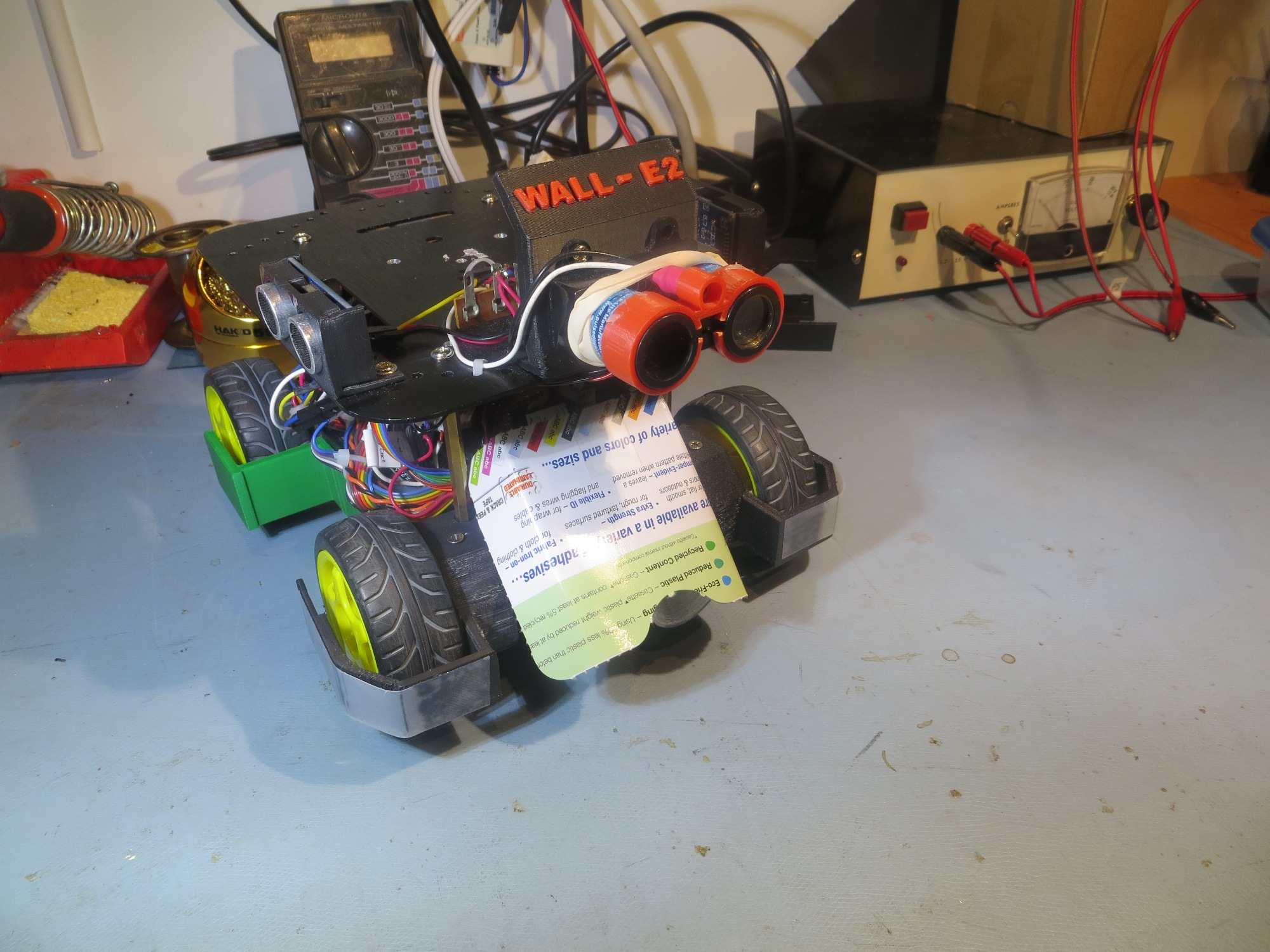
Sunshade V0. Not very practical, but does set the baseline for the rest of the tests
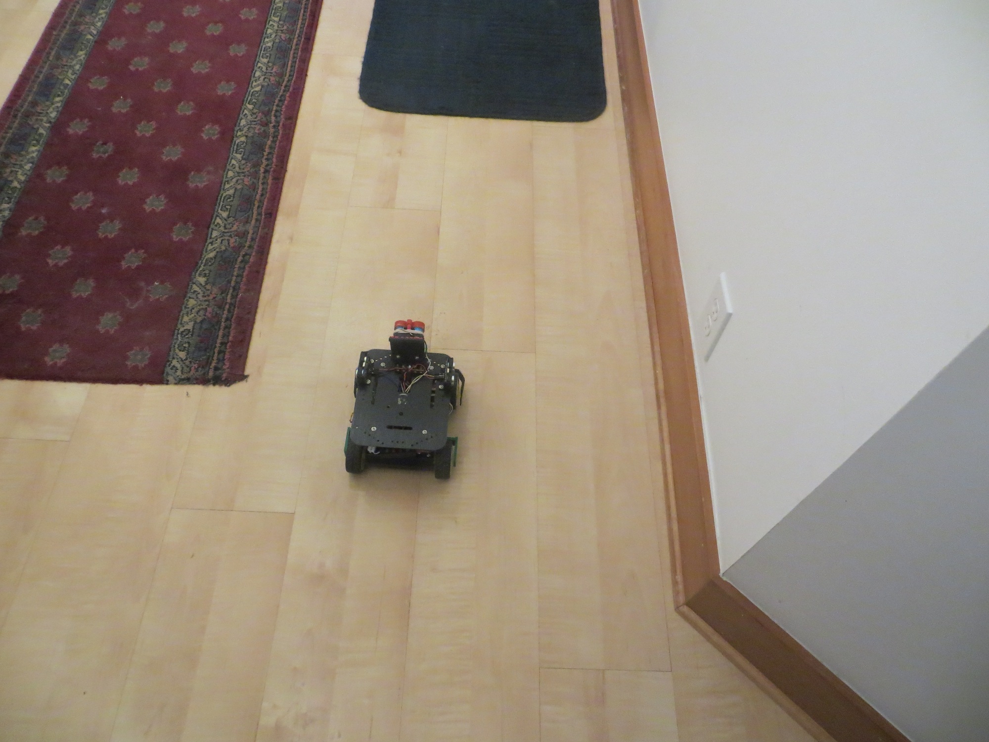
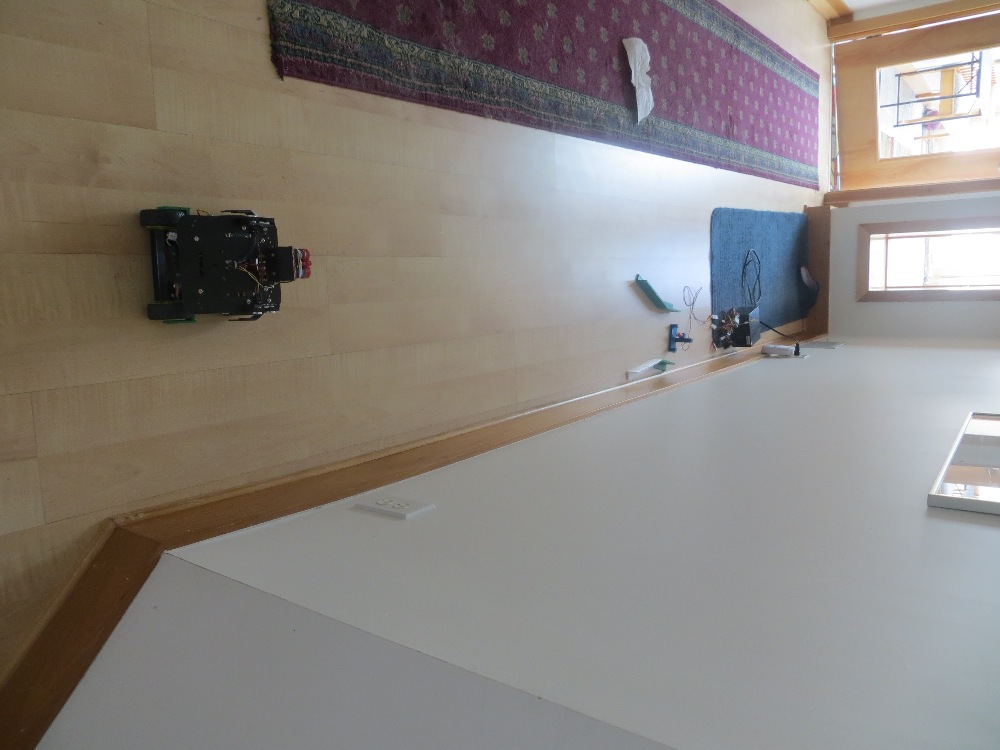
Test position for 07 April 2017 sunshade tests
With this setup, Wall-E2 was pretty much deaf to the overhead lamps, showing no reaction to cycling the lights. Of course, this configuration would also completely prevent it from detecting the charging station IR beam, but….
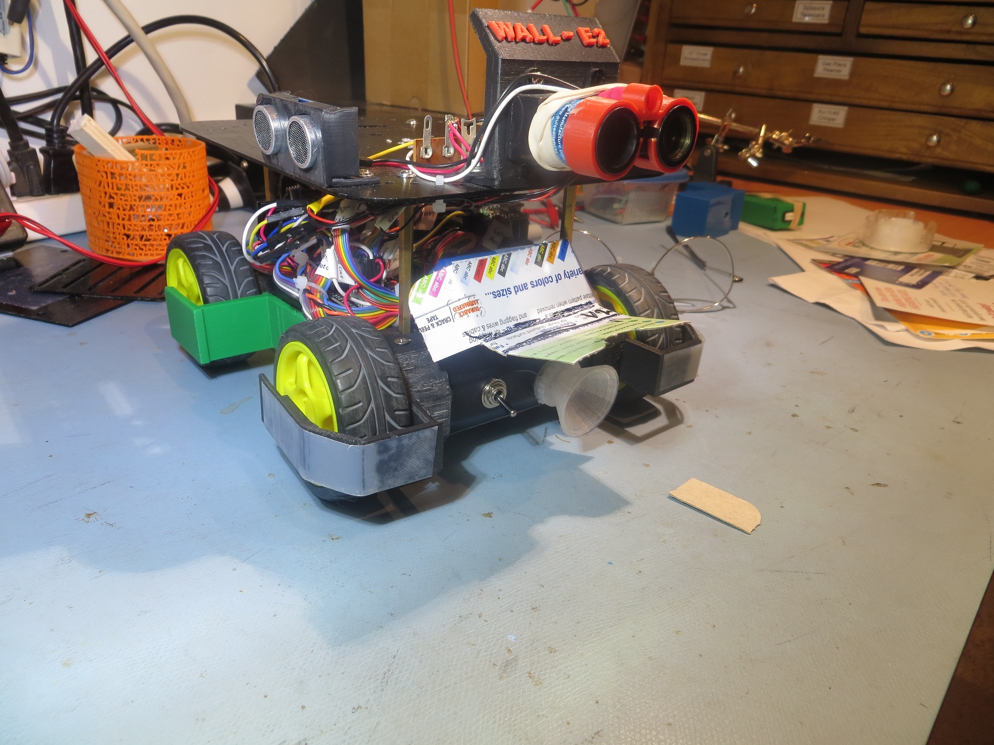
Next I modified the above V0 cover to allow a bit more visibility, as shown below:
Sunshade V1 oblique view
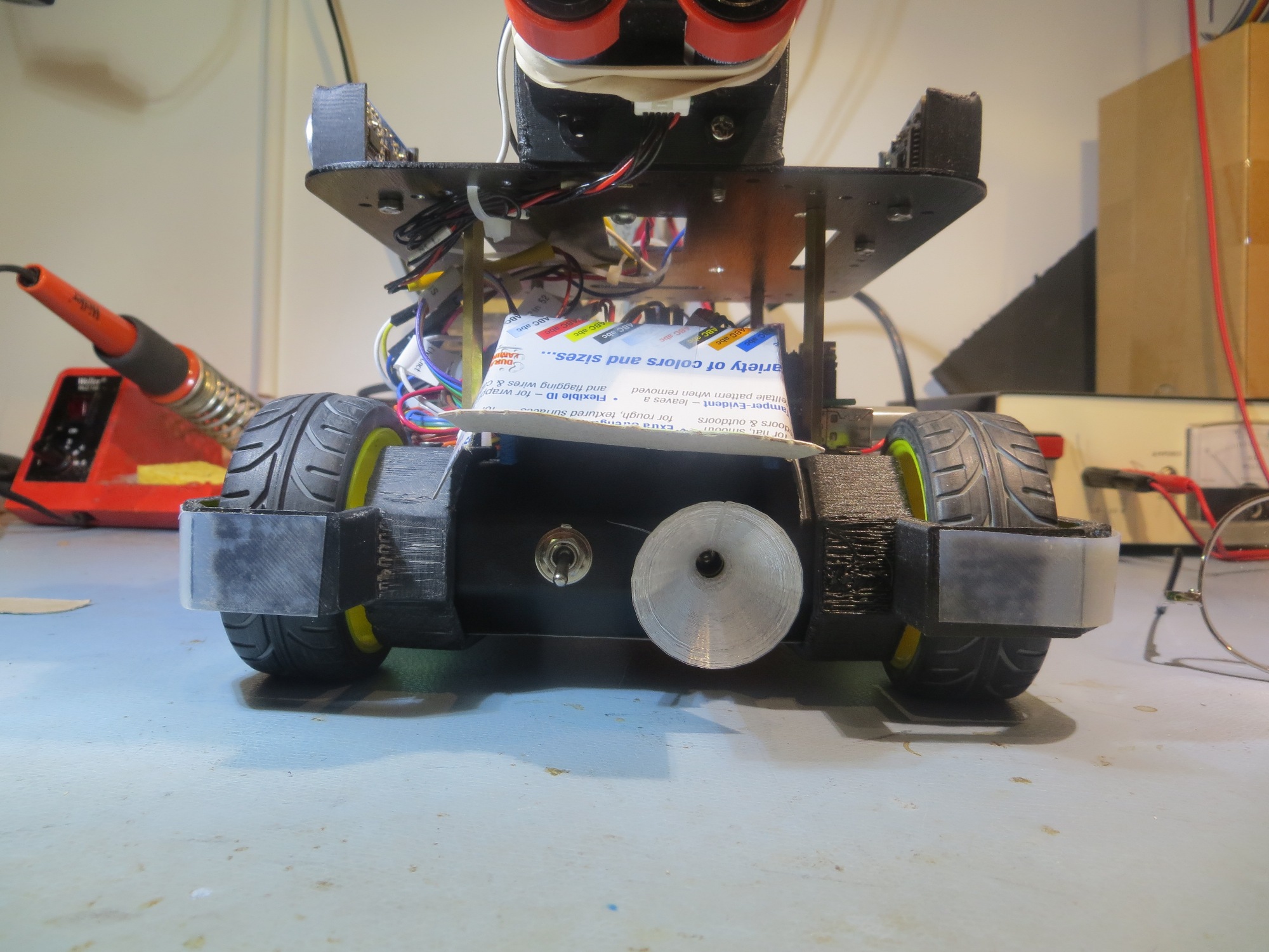
Sunshade V1 front view
This version is still a bit too restrictive for normal IR beam detection/homing, but was worth a shot for testing purposes. With this setup, the overhead lighting is noticeable, as shown below.
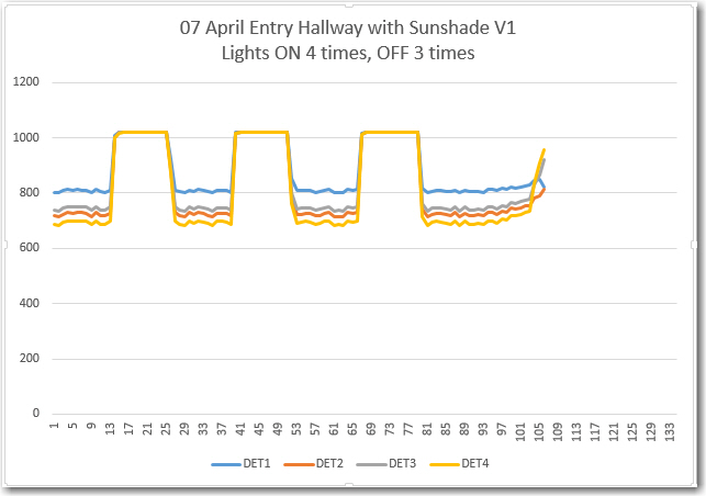
Sunshade V1 at sunshade test position. Lights ON four times for 5, 5, 5 and 10 sec
As can be seen from the plot, the V1 sunshade responds to the overhead lamp IR with an average A/D reading about 700 out of 1024.
Next, I modified the sunshade again so that it would just allow the IR detector module to ‘see’ straight ahead, on the theory that that would be the minimum requirement for successful IR beam detection/homing. With this setup, the overhead lamp response was stronger, but still not completely overbearing; the IR detector response to the overhead lights averages A/D values of about 600 out of 1024.
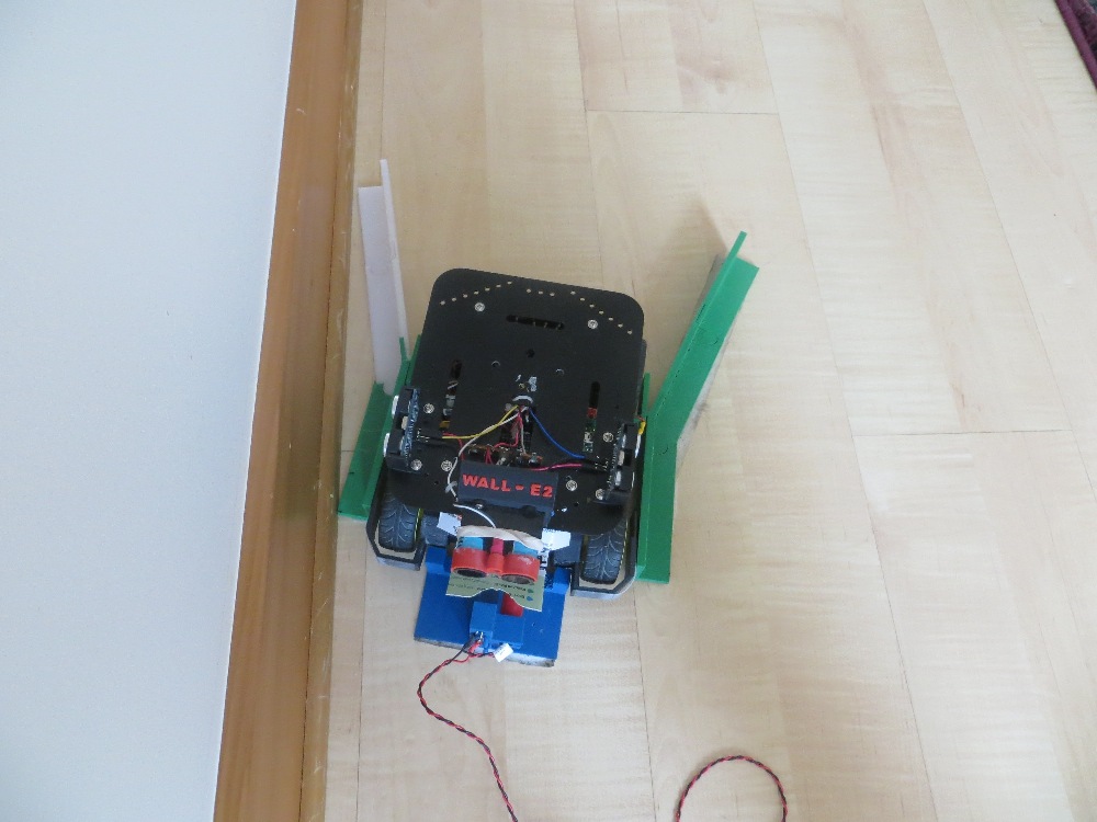
Sunshade V2 oblique view
Sunshade V2 front view. Note IR detectors visible from directly in front
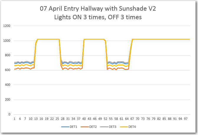
IR detector response to overhead lamps. ON three times for 5 sec each
When I ran a homing test with the V2 sunshade in my lab (with LED overheads, not incandescent), the robot homed successfully from about 1 m away, with the following IR detector/homing performance
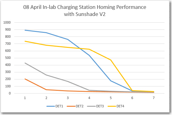
In-lab (LED overhead lighting) charging station homing performance with V2 sunshade
In the above homing test, the IR detector values started out at approximately 900, 200, 450 and 750, respectively. This means I could set the IR beam detection threshold at, say, 400 and still have a 200-count noise margin in both directions (200 down from the overhead IR flooding value, and 200 up from the typical 1-meter IR beam intensity). From the movie it is obvious that the minimum IR reading is switching back and forth between at least two detectors, so I think it is safe to say that IR homing would occur even in the presence of a 600 unit noise level, as the 200 or lower reading switched between detectors.
Next, I moved the charging station into the entry hall so I could test IR homing performance with the overhead lights on and off. My prediction was that Wall-E2 should be able to home successfully in both cases. For the test, the charging station lead-in rails were oriented in the preferred ’tilted’ orientation, as that should give the best homing performance, as shown in the photos below:
Hallway IR homing test setup
Robot shown in captured position. Note lead-in rail ’tilt’ relative to the wall
I made three runs; Lights ON, lights OFF, and Lights ON, as shown in the three video clips below:
As can be seen in the videos, Wall-E2 successfully homed to the charging station with the overhead lights OFF, but not with them ON – bummer!
So, further testing will be required to determine the particulars of the two failed runs, and what – if anything – can be done about it.
After moving my laptop out into the hallway so I could capture telemetry from the robot while also filming the runs, and checking everything out, I made two successful IR homing runs – one with the overhead lights ON, and another one with them OFF. I captured telemetry from both runs, and was clearly able to distinguish between the lights ON and OFF scenarios. The videos and the telemetry plots are shown below:
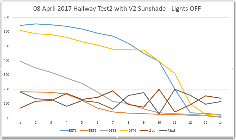
08 April 2017 Hallway Test2 with V2 Sunshade – Lights OFF
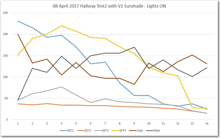
08 April 2017 Hallway Test2 with V2 Sunshade – Lights ON
From the above plots, the lights ON & OFF conditions are readily recognizable. In the ‘OFF’ condition, the ‘background noise’ is at about 600-700, and the IR beam is at 100-200. In the ‘ON’ case, the noise level is higher (lower count), at about 150-250, but the IR beam is lower too – around 50-150. I guess this makes some sort of sense, as the IR energy from the charging station beam is a separate, additive source relative to the overhead lighting. Also, both plots show good motor response curves – the left & right motor speeds are obviously being adjusted rapidly in response to IR detector changes.
So, at this point I’m pretty convinced that the V2 sunshade is working, so I plan to print up a permanent version that will (hopefully) simply slide on to the front of the existing charge status display panel.
Stay tuned!
Frank
Pingback: Charging Station System Integration – Part III - Paynter's Palace
Pingback: IR Modulation Processing Algorithm Development – Part XVII - Paynter's Palace