Monthly Archives: March 2017

Charging Station Design, Part XIII – More PID Tuning

Posted 28 March 2017

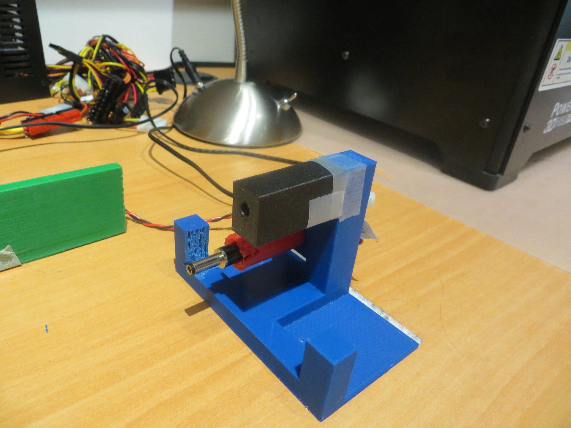
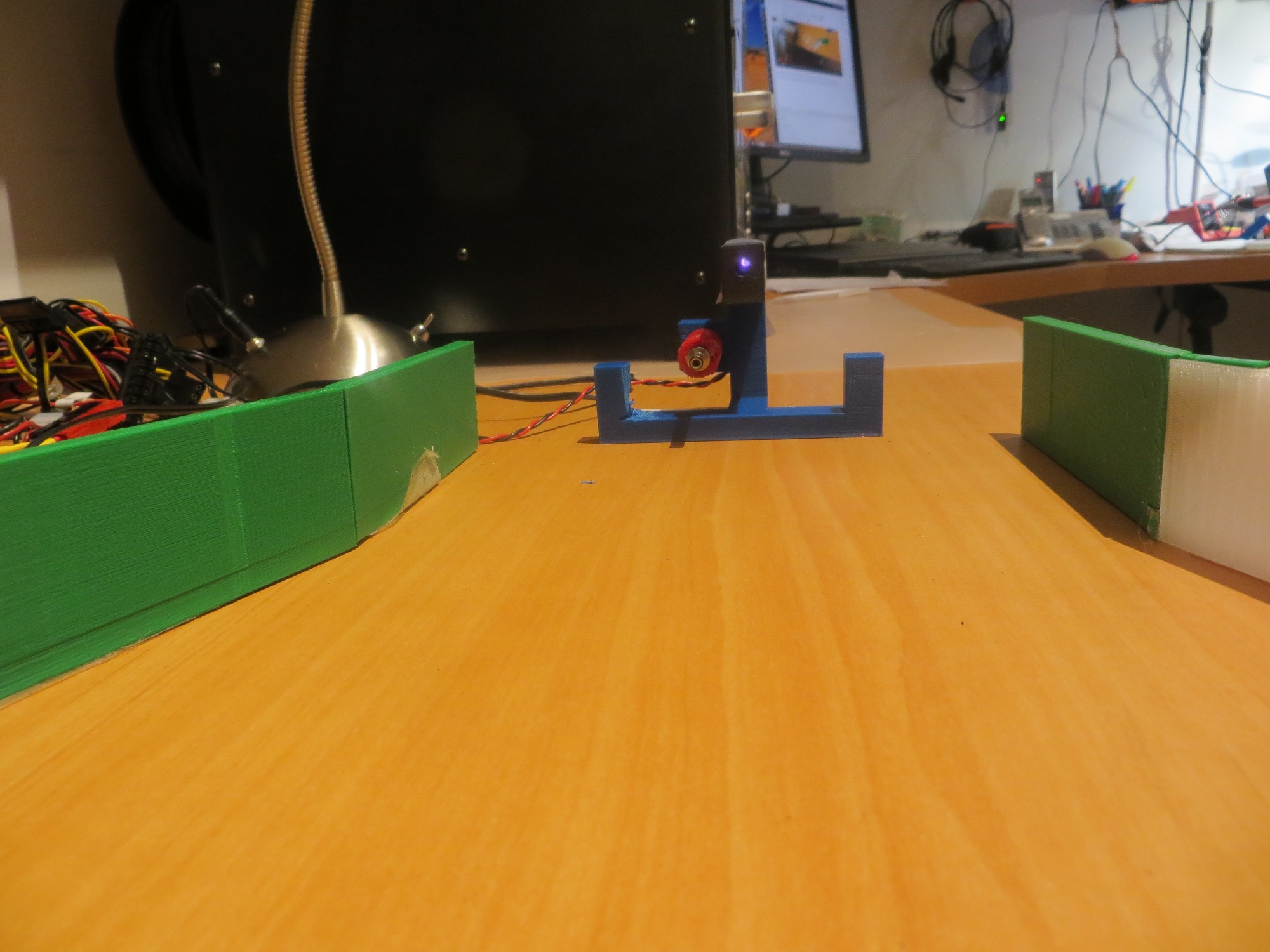
After my cleanup-and-label campaign documented in my last post, I was ready to get back to PID tuning for homing in on the charging station.  When my grandson was here, he pretty much took over my primary work area, so I was forced to move my bench-top testing range to another part of my bench.  This was not quite as convenient for reprogramming the bot, but it did give me a bit more distance between the initial bot position and the IR LED in the charging station, as shown in the following photo

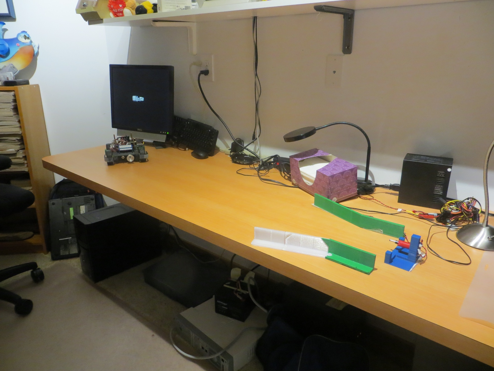
Wall-E2’s new PID test range

I started out by going back to the simplest possible PID setup – namely (p,i,d) = (1,0,0) and ran a series of range tests, as shown in the following video.

As is evident in the video, Wall-E2 has no difficulty homing into the charging station when initially placed near the edge of the bench, but won’t home properly from the other side.  After thinking about this for a bit, I came to the conclusion that the reason for this is that the center of the charging station is physically located near the edge of the bench, so when the bot starts at that edge, it is actually close to the centerline of the charging station, and therefore is almost perfectly lined up at the start. When starting from the other side however, the initial position is not lined up with the charging station centerline and therefore has to make more of a correction to get lined up.  From this I hypothesized that the PID setting of (1,0,0) doesn’t provide enough of a wheel-speed correction to make the required turn.

So, next I tried a PID of (2,0,0), and this worked much better, as shown in the following video

As can be seen from the first run above, the robot is doing a much better job of homing, but unfortunately ran into the left side rail instead of being captured.  This turns out not to be a PID tuning issue, but rather a problem with the IR beacon pattern relative to the lead-in rail arrangement.  The line from the robot’s starting position to the IR LED unfortunately intersected the outside of left lead-in rail instead of the inside.

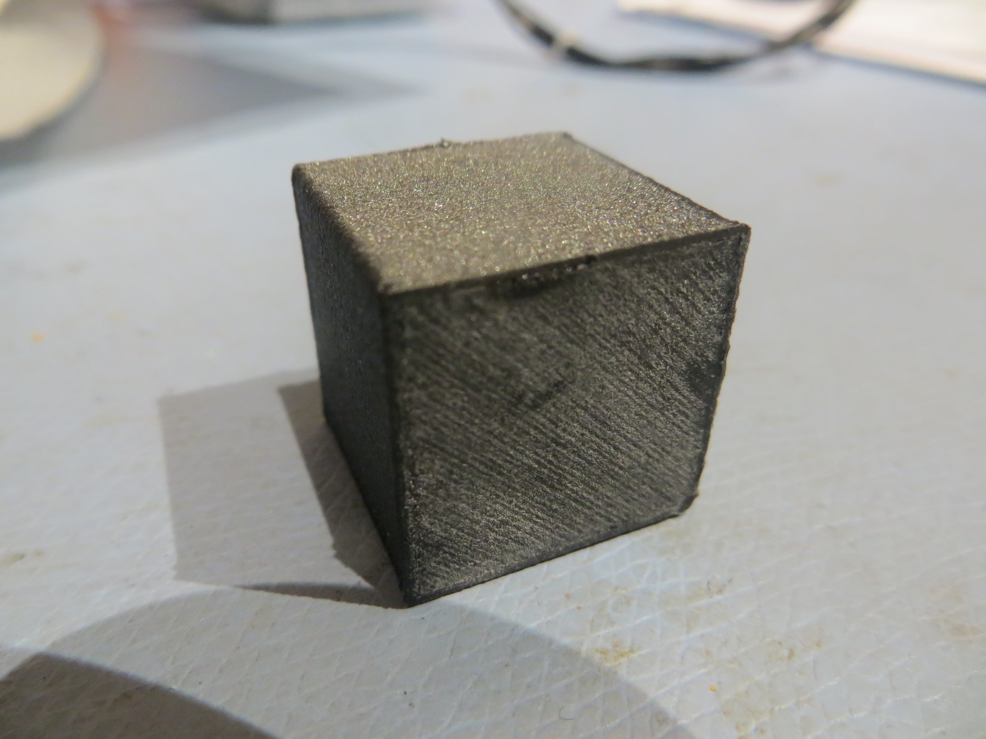
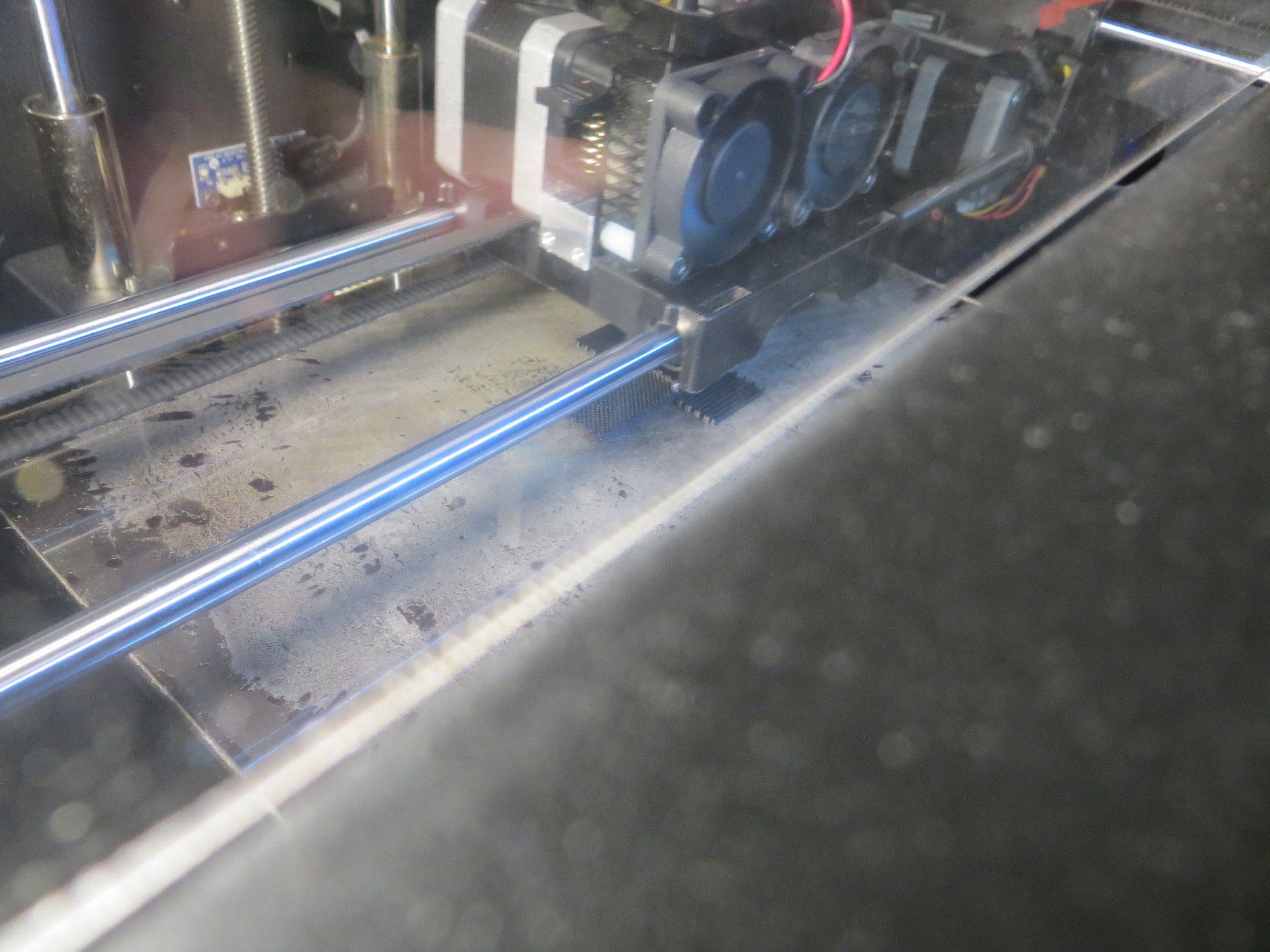
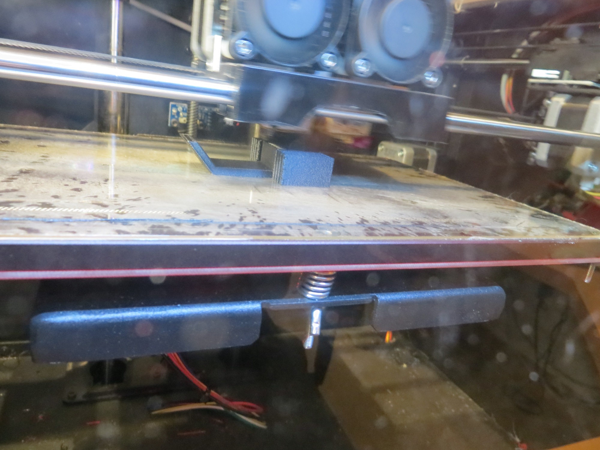
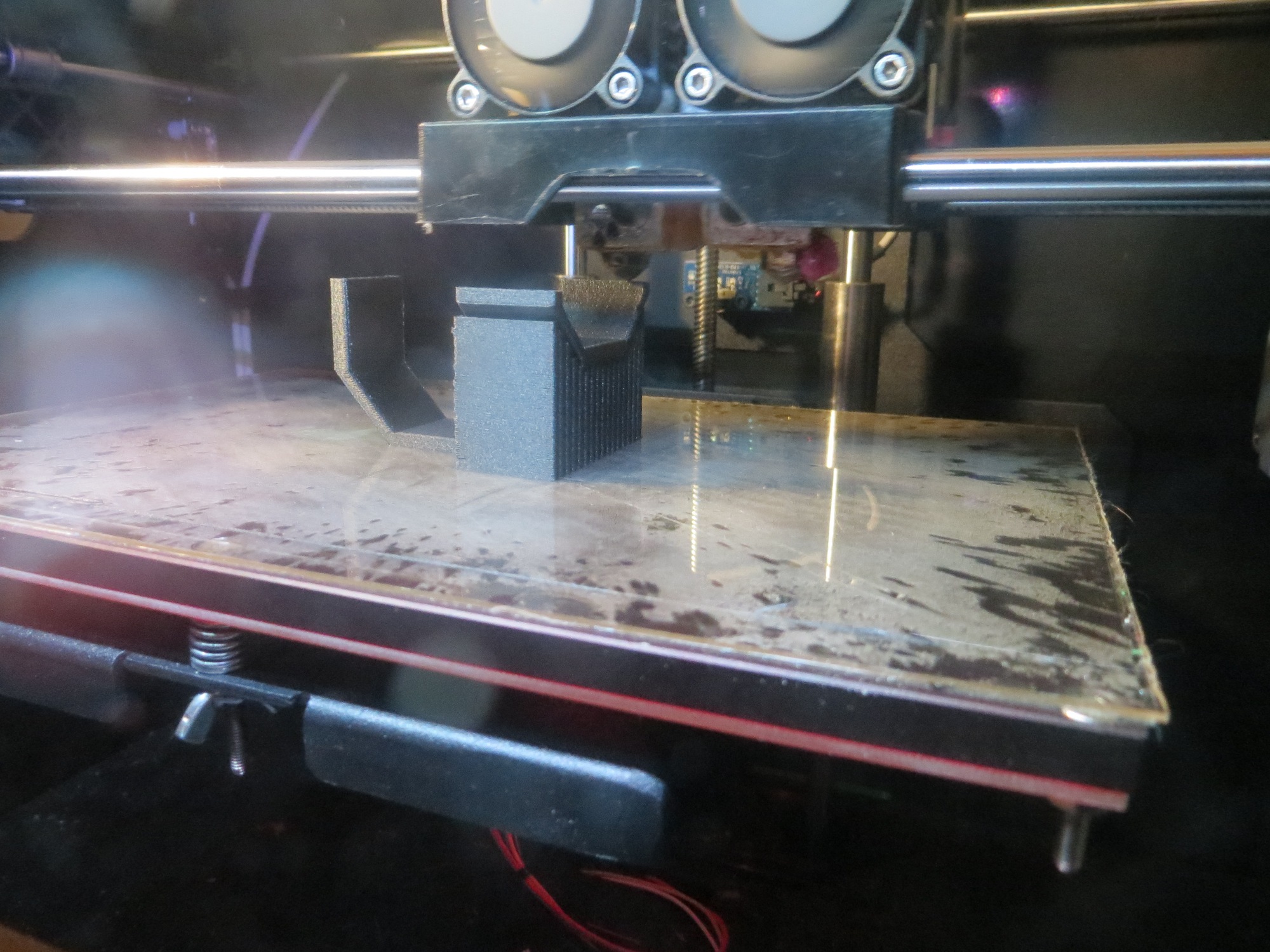
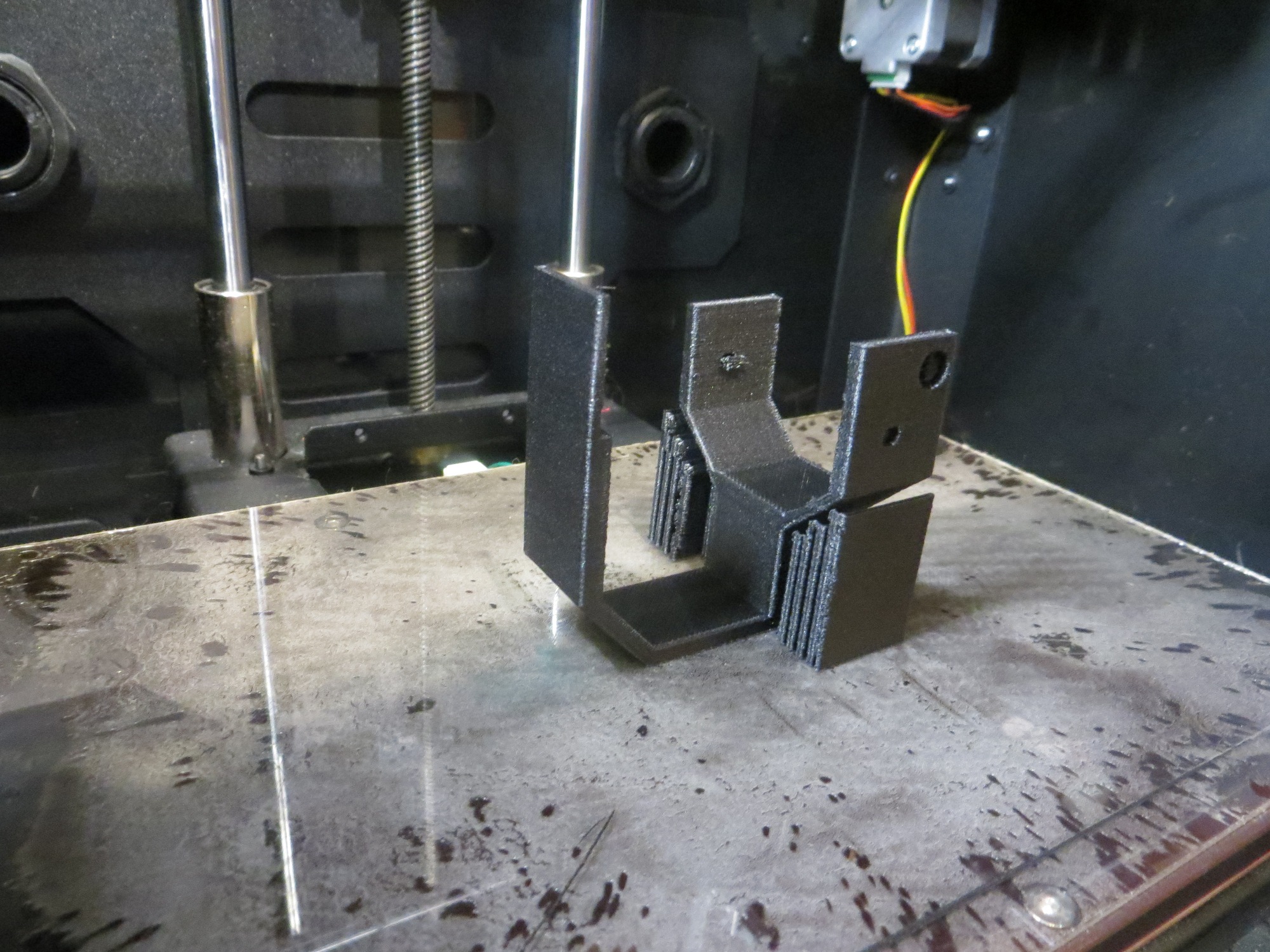
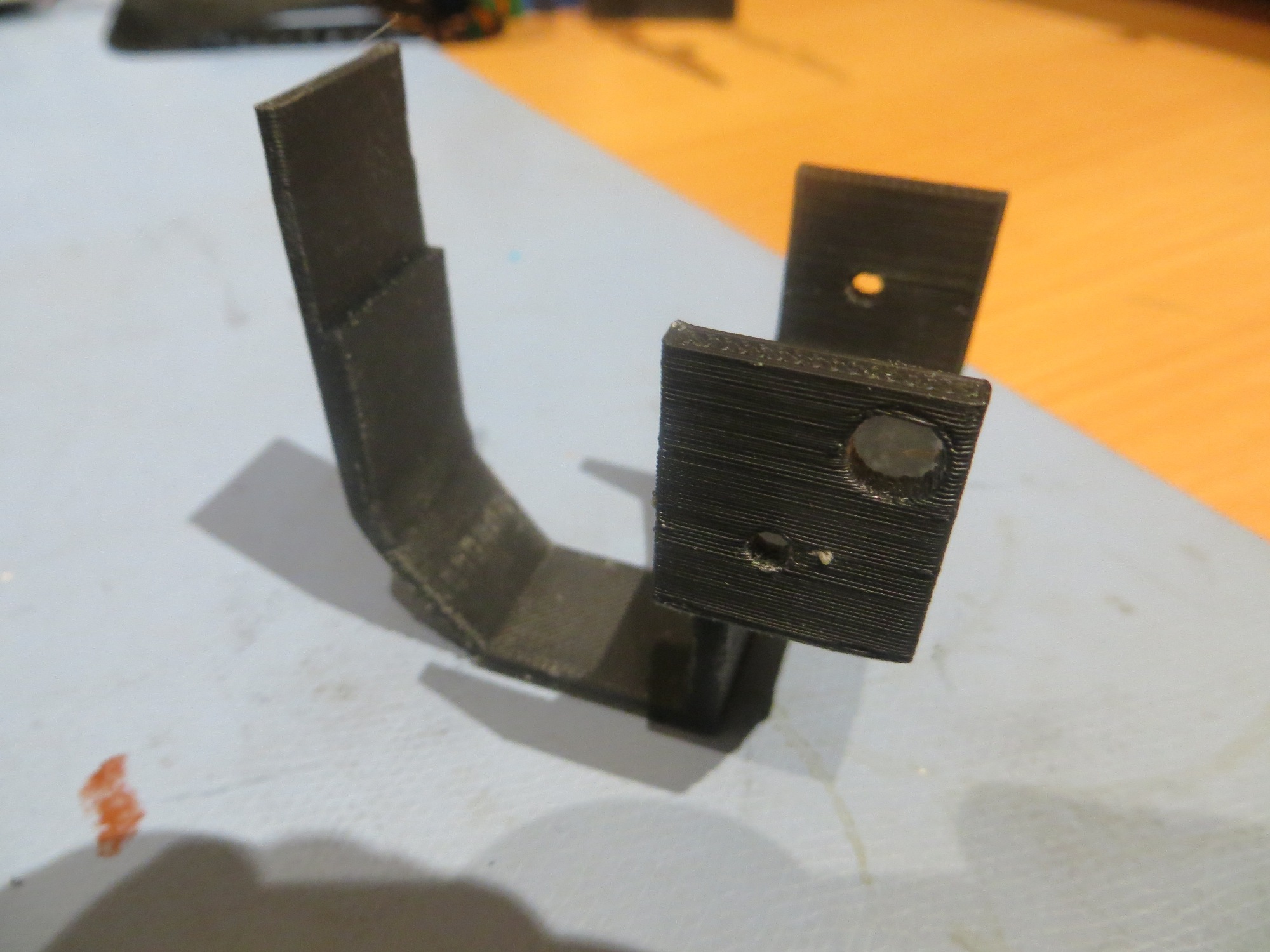
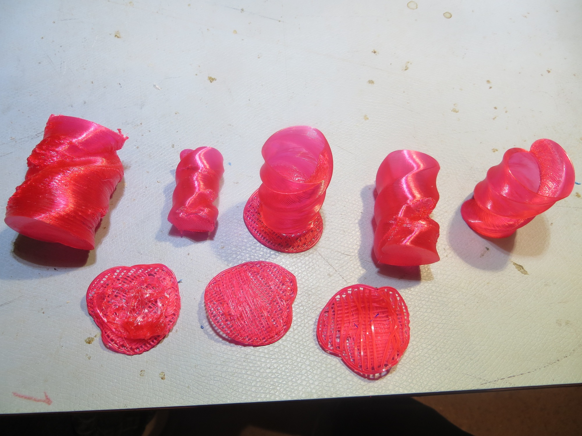
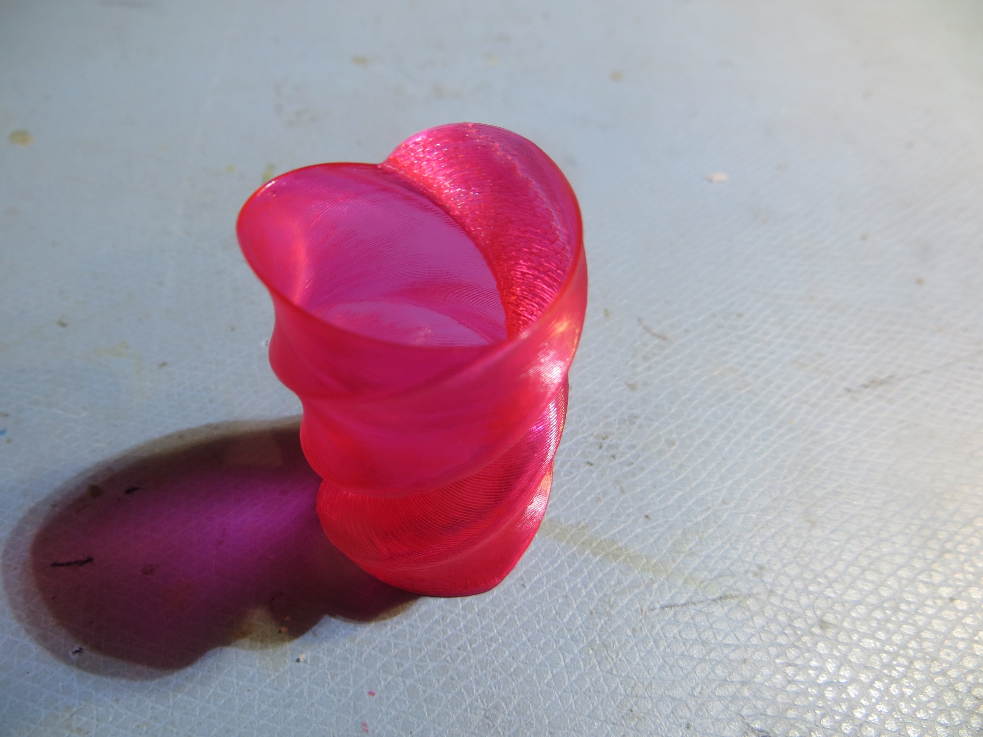
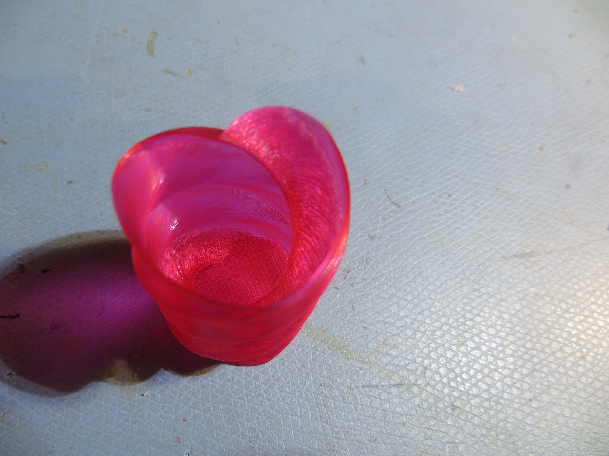
As an experiment to confirm the IR beam pattern hypothesis, I printed up an auxiliary part to restrict (not collimate, as that implies shaping) the beam to a narrower pattern, as shown in the following photos  ( taken with a digital camera with a wavelength range that covers the  IR wavelength being used)

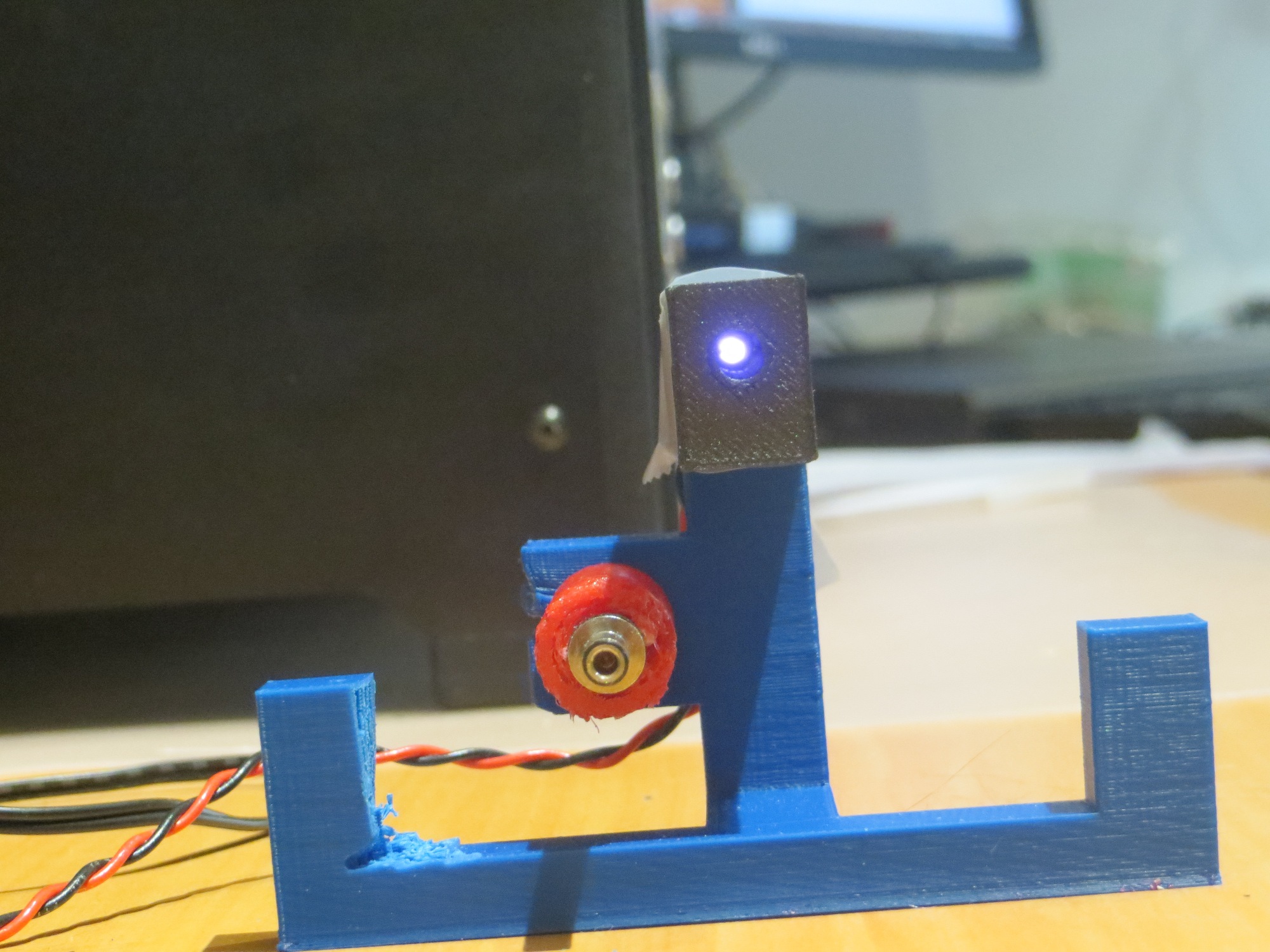
This experiment ‘worked’ in the sense that it showed that the IR beam was no longer visible outside the lead-in rail aperture, but it also made it so narrow that the robot had to be right on the centerline to sense the IR beam at all.  Although this solves the problem of hitting the rail, it would make it very difficult for the robot to ever find the charging station in the first place when approaching at the typical wall-following standoff distance.

So, although I plan to do a bit more fine-tuning of the PID parameters, it appears that the basic homing problem is solved,  but the challenge now is  getting the robot into a position where it can home in on the IR beam without running into a side rail.  The current wall-following algorithm doesn’t have a set stand-off distance, so the robot may be ‘cruising’ at anywhere from 10-70 cm from the wall being tracked.  Assuming that one lead-in rail is against the wall, the IR led is located about 20 cm out, and the front end of the outside lead-in rail is about 35 cm out.  When the robot is just captured by the outside rail, its centerline is about 16 cm out.  The angle from the IR LED to the center of the robot at this point is about 11-12 º.  So, assuming the robot is wall-following and at some point intersects the IR beam and starts homing, the angle from the robot to the IR LED has to be less than 11-12 º or the robot will not be captured by the lead-in rails.  The situation is shown graphically in the following diagram.

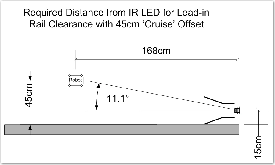
Capture parameters for the robot approaching a charging station

As shown above, if the robot is ‘cruising’ at 45 cm from the wall, then it has to start homing from no less than 1.7 m or so from the charging station in order to get captured by the lead-in rails.  This is  a large, but impossible distance.  The robot can currently home from about 1 m out, so getting out to 1.7 m might be as easy as increasing the IR LED current;   it is  currently running at about 30 mA, and it is rated for 100.

Another possibility is to angle the capture gate out slightly with respect to the wall. There’s no real reason the charging station rails need to be parallel to the wall – it’s just my neat-freak mentality that makes me do things that way.  If I angle it such that the inside lead-in rail touches the wall at both its forward and trailing ends, that will angle the beam out at about 13 º, and move the minimum capture distance in to about 1.0 m, as shown in the following diagram.  1.0 m is just about where the robot is capturing now – yay!!

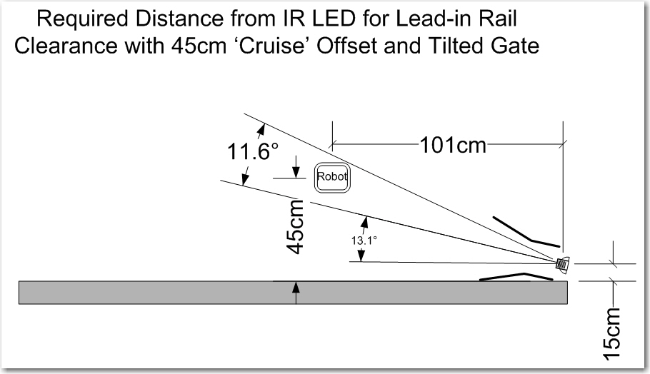
Tilted gate option. The tilt decreases the minimum required IR beam capture distance from about 1.7m to about 1.0m

So, it appears that tilting the capture gate is the way to go; this doesn’t cost anything but a slight ding in my ‘neat-freak’ index, and should  eliminate or greatly reduce problems with charging station capture failures.

Stay tuned,

Frank


Charging Station Design, Part XII – A Pause to Clean Up

Posted 22 March 2017

This last weekend was devoted to a whirlwind visit by the St. Louis family, which includes my 13-year old, growing-like-a-weed, 3D printing enthusiast grandson.  So, I didn’t get a whole lot of time to work on Wall-E2’s problems, as Danny basically took over my entire lab ;-).  So, now that the horde (can one 13 year-old kid constitute a ‘horde’?) has departed, I can get back to some sort of normalcy and make some progress.

At the end of my last post on this subject, I had concluded that I needed to go back and verify the details of the IR homing hardware and software, as the results I was getting didn’t make sense.  So, I set up some experiments where I could carefully watch the raw output from all 4 IR detectors, and the changes from physically blocking one IR LED at a time.  This experiment convinced me that something was definitely wrong with the hardware; at least one detector appeared to be dead, and it also looked like blocking one detector affected the outputs of more than one – strange!

So, back to the hardware; After dismounting the combined charge status display panel/IR detector module and separating the two, and physically inspecting the IR detector module I  found  a bad solder joint (what – a bad solder joint!?  I  never make bad solder joints! – must have been someone else!) on one of the detector connections to the interface  header.

After repairing the bad solder joint, I carefully worked my way through the cabling maze on Wall-E2 to the microcontroller end of the IR detector cable, to verify proper connection on that end.  The connections looked good, so I did some more testing, only to find that one of the IR detector outputs appeared to be dead – it’s analog reading stayed around 4-500 no matter what I did.  Some more physical inspection revealed the problem – my 4-pin IR detector cable was connected to A2-A6 on the Mega board, but I was reading A1-A5, so the A1 input was essentially ‘open-circuit’ – oops!

After fixing this booboo, things started to perk up and act a *lot* more normally! ;-).  However, instead of immediately going back to testing mode, I decided that I needed to get serious about labeling and indexing cables (I use red fingernail polish to index one end of each connector to the corresponding microcontroller pin) and connectors  on Wall-E2, so I would have less trouble in the future with the large number of ribbon cables and loose wires now festooning the robot.   Fortunately I have my wonderful Brother P-touch label maker to help me with this task. As an aside, if you are a ‘maker’ hobbyist like myself, a label maker is an absolute godsend, and I can’t recommend the Brother P-touch highly enough.

After my labeling and cleanup campaign, Wall-E2 is  a lot more self-documenting, as shown in the following photos

Printing with 3DXTech Carbon-Fiber PETG – Solved!

A couple of months ago, I got some 3DXTech carbon fiber PETG filament to play with, and I have been having mixed success printing with it on my PowerSpec 3D PRO (FlashForge Creator PRO clone) dual-extruder machine.  My first few prints were pretty nice, but lately I’ve been having problems.  The prints turn out messy and stringy, with almost no strength – as if the layers aren’t fusing at all. I can easily snap pieces apart, where before they were quite robust.

In an effort to troubleshoot the problem, I have done the following:

  • Replaced both nozzles with 3DxTech hardened steel models
  • Re-leveled the build plate
  • Gone through the excellent XYZFABS PETG printing tips here.
  • Set the z-axis offset to 0.02mm in S3D gcode
  • Set the filament feed multiplier to 0.88 as recommended
  • Set the extruder temp to 220, bed temp to 100

With the above settings, I tried a 20mm cal cube, but it  started ‘air-printing’ after about 15mm from the base (filament under feeding?).

  • Set the filament feed multiplier to 1.20 and tried again.  This time I got a nicer print, but it still failed at 15mm with a feed jam and obvious gear tooth wear on the filament – clearly over-feeding.
  • Set feed multiplier back to 1.10 and tried again.  This time it started ‘air-printing’ at about 4mm up.
  • Changed extruder temp to 230 and tried again.  This time it failed to adhere 1st layer to print bed.  This caused a ‘blob’ on the extruder tip, which resulted in sidewalls that were over-printed and ragged.
  • Changed print multiplier to 1.00 and tried again.  This time the print didn’t adhere to the print bed at all
  • Changed z-axis offset back to 0.00.  This resulted in an almost perfect print.  Sidewalls were very nice, and although there was some ‘globbing’ during bridging on the top, the final top layer was almost perfect.

So, the final settings for a good print are:  Feed multiplier = 1.00, Bed temp = 100, extruder temp 230, z-axis offset 0.00, unused extruder temp set to 25 (can’t set to 0, as this gets overwritten by printer), as shown below in the S3D process settings screenshots

23 March Update:

Last night I printed a second 20mm cal cube using the same settings as above, and this time the bottom layers did not print correctly (sides and top did OK).  So I tried again this morning, with the following change:

  • Changed z-axis offset from 0.00 to +0.01mm, and changed the unused extruder temp from 25 to 75 (this last settings change is an attempt to fool the printer into showing percentage completion as normal. With an unused extruder setting of 25, the top line of the display shows ‘heating’ continuously)

With the above changes, I got an essentially perfect cal cube print, *and* the top line of the display showed percentage completion instead of just ‘heating’ (the right extruder temp display showed 75/75, so that pretty much confirms my theory about the printer having to match actual and requested temps in order to progress to the ‘percentage completion’ display mode)

Essentially perfect 20mm cal cube print with 3DXTech Carbon Fiber PETG filament

Unfortunately, when I tried to print the TinkerCad model shown below (it’s the front right wheel bumper for my robot), I could not get a decent print no matter what I did.  Either the first layer wouldn’t adhere, or the filament feed failed partway through the print, or the finished print was way to fragile for use.  I finally had to give up on the 3DXTech filament entirely and print the bumper using ABS (which printed perfectly the first time!).  This was very disappointing to me, as I had previously successfully printed two of these wheelguards using the 3DXTech filament – so I’m not sure what changed to make it difficult/impossible to do it now 🙁

Right wheel guard for Wall-E2 (blue material is support). Printed perfectly the first time with ABS, but not with 3DXTech Carbon Fiber

ABS with ABS support printed perfectly on the first try

Frank

25 March Update:

Yesterday I did what I should have done when I first started having problems with the filament, namely shooting off an email to 3DXTECH.  I quickly got a response back from Matt Howlett, the  company’s founder, with a what looks like their stock reply for people having problems.  Most of the stuff in the list I had already covered, but there were a couple I hadn’t tried, and one of them was raising the extruder temp from 230 to 240-245.

So, I reloaded the carbon fiber PETG on my printer, and printed a 20 mm cal cube with Matt’s recommended settings, except for a bed temp of 90 vs 65 (because I have a PEI bed and don’t want to use hairspray, and print speed of 3000mm/min vs 4000.  This time the cal cube printed perfectly, and I could not damage the finished cube with finger pressure like I could before.

Next, I tried a full print of my right wheel guard model for Wall-E2.  To simplify things, I used the carbon fiber PETG filament for both the model and the support material (I was having trouble before getting the support material to stick at the bed temperature I was using for the carbon fiber PETG material), and lo-and-behold, this print also turned out perfectly, as shown in the following shots.

Just starting the print

About 1/4 the way through, printing nicely

About 2/3 of the way. Note how well both the model and the support area adhered to the bed

Finished print!

Finished product – and quite strong.

When I made this one change, all of a sudden I was getting almost perfect prints!  Now I feel like an idiot for going through all this wailing and gnashing of teeth when all I needed to do was raise the extruder temp 10 deg!  Now I have been forced to ‘eat my hat’ (and my complaints to 3DXTECH!) – OOPS!!  However, since I am now back to being able to make strong carbon fiber prints, I’m more than willing to accept the trade-off! ;-))))

Stay tuned,

Frank


Charging Station Design, Part XI – PID Tuning

Posted 14 March 2017

As I was doing the IR homing tests described in my last post, I noted that Wall-E2 wasn’t all that great at homing; in particular it missed the opening in the lead-in rails on several occasions, instead hanging up on one side or another.  This was a bit mystifying to me, as I thought I had the homing code working very well with my old 3-wheel robot (see ‘IR Light Follower for Wall-E2, Part X – More PID Tuning‘).  At the time, I decided to use one of my best scientific research tools and simply ignore the problem, hoping it would either go away, or my subconscious mind (by far smarter than my conscious one!) would figure it out in the shower or while drifting off to sleep.

And, in fact, last night while drifting off to sleep, I remembered that the PID tuning for the 3-wheel robot had to take into account the fact that  even small  differences in drive wheel speeds get magnified by the free-castering front wheel.  Wall-E2, with its all-wheel drive  behaves entirely differently, and since small wheel speed differences don’t get amplified into big directional changes, the PID tuning parameters appropriate for the 3-wheel version are too passive for the 4-wheel one.

So, I went back to the drawing board (again!) for PID tuning for the 4WD Wall-E2, starting with the current 3-wheel parameters as the ‘too passive’ baseline.  From my previous article, the final PID parameters were P = 0.1, I = 10, D = 0.2, with the input scaled by 1, 5, or 10 depending on IR beam signal strength.  My initial thought is that the 4WD robot needs a lot more ‘D’ (differential) to increase its turn rate with respect to IR beam heading changes, so I tried a couple of runs with the D value increased from 0.2 to 2 (factor of 10 increase).  As the following video shows, this did seems to increase Wall-E2’s agility somewhat, but still not enough to overcome even minor initial heading offsets, especially to the left.

After some more testing with different values of P,I,D, I began to wonder if I might be having problems with the basic IR detection hardware and homing software, independent of the PID tuning issue.  When I did the previous PID study, I also captured the raw detector data, which allowed me to determine how the PID tuning and the basic detection hardware/software were interacting.  I may have to go back and do that again with the 4WD setup

Stay tuned,

Frank


Charging Station Design, Part X

Posted 11 March 2017

The last few days have been spent partially implementing the software structure and state design described in my ‘Wall-E2 Operating Mode Review‘ of 06 March.  Up to this point, the only thing Wall-E2 knew how to do was wall-following, but there were (and still are) a number of ‘sub-modes’ associated with wall-following.  Now all of this code has to be grouped into the  ‘Wall-Following’ state/function under the main program, and the new ‘Charging’ and ‘IR Homing’ state/functions added.

For purposes of testing, I decided to basically comment out all the wall-following code and concentrate on the IR Homing and Charge modes.  To do this, I added the new operating mode determination and top-level case switching code at the top of ‘loop()’, and left the MODE_WALLFOLLOW: case un-implemented.  the MODE_CHARGING code is all new, but the MODE_IRHOMING code was copied from my previous work with the 3-wheel robot last November.

After getting most of the MODE_CHARGING and MODE_IRHOMING code implemented, I ran some bench tests to see how well things work.  After finding and fixing a number of typos, logic errors, and downright goofs, I was able to video a successful IR home to charge, followed by a charge-completion  disconnect (instead of waiting for a full charge termination, I tied execution to manual charge plug disconnect).  Here is the video


A couple of side notes from the above video

  • It is evident that the IR homing with PID works very well, to the point where the lead-in side rails almost aren’t needed (but only ‘almost’, I fear)
  • The fixed charging station fixture isn’t quite high enough.  In order to more accurately line up with the center of the charging port, I had to raise the fixture by about 5mm
  • The disconnect routine backs up far enough, but doesn’t quite make a complete 90 º turn.  I should be able to tweak the turn duration a bit to make that happen.

So, at this point, I think I have most of the new parts of the operating system working, although some parts are hard to test due to the long charge times.  Here’s what I think remains to be done:

  • Reconnect and test the LIDAR and ping sensor hardware; this will be required to test wall-following and the charge station avoidance sub-mode
  • Reprint the charging station fixture with 5mm more height
  • Set up the full lead-in rail arrangement and confirm proper homing/engagement, along with proper dis-engagement, and proper avoidance when the battery isn’t low.
  • re-implement and test the wall-following code in the new structure, as MODE_WALLFOLLOW.  This  should be just a bunch of cut-and-paste operations.
  • test the various ‘normal’ state transitions; wall-follow to IR homing to charge monitoring to wall-following
  • test the wall-follow to IR homing to charge station avoidance transition.
  • fully test the end-of-charge scenario.

12 March Update

I reconnected the LIDAR and ping sensor hardware, and confirmed (not without some wailing and gnashing of teeth!) proper operation.

I reprinted the charging station fixture with a 5mm pedestal, and transferred the LED/charging plug from the old fixture to the new one.

Set up the lead-in rails on my benchtop so that I could test both the ‘hungry’ and ‘not hungry’ IR homing scenarios.

Tested the ‘not hungry’ scenario by setting the ‘full’ threshold back down to 7.4V (50% charge, per http://batteryuniversity.com/learn/article/lithium_based_batteries).  The following video shows one of the test runs:


13 March Update:

After a bunch of software and hardware bugfixes, I think I finally have the ‘home to charge’ scenario working, as shown in the following video clip and edited telemetry capture:

The significant parts of the video are:

  • The POST test  in the first few seconds
  • The successful IR homing operation
  • The successful charger plug engagement.  When the robot senses the charger plug, it commands the motors to stop.
  • Just after the charger plug engages, the charger’s battery relay is enabled, which disables power to the motors (note the red motor controller power LED goes OFF).
  • For this test, the BATT_CHG_TIMEOUT_SEC parameter was set to 10 seconds.  Rather than wait the entire 10sec, all but the first few and last few seconds were clipped.  Note that after the 10sec timeout, the robot disables the charger relay which re-applies motor power to the robot (note the red motor controller LED is re-enabled), and the robot backs off the charger plug.
  • The robot now backs completely clear of the lead-in rails, and turns away from the nearest wall before going back to wall-following mode.

I have also posted an edited version of the telemetry captured during this test.  As you can see, the robot transitions to IR homing mode, successfully homes on and engages with the charging plug, monitors the charging process, an then executes the ‘ExecDisconManeuver()’ to disengage from the charger and back out of the charging station area.

Loader Loading...
EAD Logo Taking too long?

Reload Reload document
| Open Open in new tab

Download


Stay tuned,

Frank


Wall-E2 Operating Mode Review

Posted 06 March 2017

At this point in the 4WD robot’s development, I think it might be time to review all of  Wall-E2’s different operating modes, and  what external sensor conditions determine which operating mode is active.  Previous to this point, the robot had only one operating mode – the ‘Wall-Following’ mode.  Now that the new battery pack has been added, along with the new capability for homing in on an IR beam to connect to a charging station has been added, the robot operating system must be enhanced to manage the additional operating modes.

Operating Modes/States:

  • Wall-Following:  This is the ‘normal’ operating mode, active when nothing else is going on (no IR beam present, no charging voltage present)
  • IR Beam Homing: Occurs when an IR beam is detected.  In this mode, a PID controller determines wheel speeds in an attempt to home in on the IR source.  This mode has two distinct sub-modes, depending on the battery state of charge.  if the battery is relatively full, then the front obstacle avoidance distance is  increased such that the obstacle avoidance turn will occur before the robot gets captured by the lead-in side rails.  Otherwise, the obstacle avoidance distance is disabled entirely, allowing the robot to be captured and the charging connection to be made
  • Charging:  Occurs when the robot is connected to the charger.  In this mode, the charging status lines are monitored to detect end-of-charge (EOC).  When EOC is detected, the robot backs straight out of the lead-in rail area, and then turns 90 º away from the nearest wall and transitions to wall-following mode.

Here is a draft state-transition diagram for the system

Loader Loading...
EAD Logo Taking too long?

Reload Reload document
| Open Open in new tab

Download

As can be seen from the diagram, the system starts out in the POST (Power On Self Test) state, and transitions to one of the other states depending on sensor input.

  • If no IR beam is detectable, and the charging station is not connected, then the system transitions to the normal ‘Wall-Following’ state.  The wall-following state continues until either an IR beam is detected, or  a physical connection to a  charging station is detected.  The normal exit condition from the wall-following state is via detection of an IR beam, which causes transition to the ‘IR Homing’ state.
  • In the IR Homing state, there are two possible behaviors; if the battery is more than 3/4 full (not quite sure how I’m going to define that, but…), then the robot will actively avoid the charging station by performing an obstacle avoidance 90 º degree turn at a  front distance larger than the extent of the charging station lead-in gate, and transitioning back to the ‘Wall-Following’ state.  If the battery is less than 3/4 full and a charge is desired, then the robot will continue to home in on the IR beam until a physical connection to the charging station is detected, whereupon the system transitions to the ‘Charging’ state.
  • In the Charging state, the system monitors the charging status signals, waiting for both ‘Fin1’ and ‘Fin2’ signals to become TRUE.  When this happens, the robot  backs out of the charging station lead-in gate area, executes a 90 º turn away from the nearest wall, and transitions back to the ‘Wall-Following’ state.

Here is a first cut at a system software structure chart that incorporates the above modes/states

Loader Loading...
EAD Logo Taking too long?

Reload Reload document
| Open Open in new tab

Download

Twisted Heart 3D Print Using Magenta PETG

A little over a year ago, in December 2015, I printed a ‘twisted heart’ vase for my wife, using  Gyrobot’s ‘Twisted_Heart_Vase_Hollow_-_Hi_Res.stl’ file from Thingiverse (http://www.thingiverse.com/thing:42570/#files).  At the time, I had been 3D printing for about a year using a Printrbot Simple Metal and I had just purchased some bright Magenta PETG 3D filament.  As usual I printed several versions to get the one I (actually, my wife) wanted, and wound up with a small 30% scale model that my wife used as her daily pill cup.

As it happens, this model wound up in the hands of a grand-daughter, so my wife asked me to print her a new one.  “Piece of cake” I thought; after all, I have a better printer – a dual extruder PowerSpec 3DPRO (FlashForge 3D Creator Pro knockoff) with enclosed build space and a heated print bed with PEI, the top-of-the-line Simplify3D plater/slicer, and plenty of PETG magenta filament remaining – what could go wrong? 😉

So, I tracked down the print file I used last time, threw it into S3D, scaled it down to 30%, and voila – NOTHING – WTF!!??  After some experimentation, I found that any time I scaled the print below 50%, the sidewalls disappeared – ugh!  After some due-diligence Googling, I finally gave up and posted to the S3D support forum, and in very short order I had a couple of replies. Turns out the answer was that the sidewall thickness was getting scaled with everything else, and once it got below about 1/2 extruder thickness – it got rounded down to zero thickness – duh!  Fortunately, poster Brian had the answer – tell S3D to make the object a solid model, and then set the infill to 0% and the sidewalls to 1 perimeter width – yay!

So, this got me to the point where I could actually slice the model and send it off to the printer, where I discovered an entirely different set of problems.  I don’t remember having any real problems with my old trusty Printrbot, but I sure was having them with the PowerSpec.  The PETG filament was sometimes refusing to stick to my PEI print bed surface, and when it did stick, it had a tendency to stick to itself and ball up in to a huge blob after several to many layers.  When it didn’t do any of these bad things, I would get ugly inclusions and/or voids in the sidewalls – not the kind of thing I wanted to show my wife – yuk!!

So, back to Google, looking for advice on printing with PETG.  Fortunately, after just a short hunt I came across a very detailed treatment for PETG printing by ‘Jules’ at XYZFabs.  The good news – it was very detailed and thorough, so it was very likely to cover my problem; the bad news – it was very detailed and thorough, and so required a lot of concentrated study to follow.

In my case, the problem resolution was to do the following, as suggested in the above article

  • Modified the Z-axis calibration in S3D’s G-code section to move the extruder another 0.02mm away from the print bed, to accommodate PETG’s enhanced stickiness.
  • Enabled the ‘wiping’ feature, and confirmed that I had ‘retraction’ enabled
  • Set the extrusion multiplier to 0.88 to significantly under-extrude.  Before reading this article, I had had other occasions to over-extrude slightly with others filaments, but this was the first time I had a reason to  under-extrude.
  • Switched back from ‘high resolution’ (0.1mm layer height) to ‘medium’ (0.2mm layer height).  Not sure this was really necessary, but it seemed that the theme for PETG was ‘keep the layer separation as high as possible without actually air-printing’, so…
  • Slowed the print speeds down slightly.  Again, not sure this was absolutely necessary, but the combination of this and all the above were definitely going in the right direction.

As a result of these changes, print quality improved dramatically, to the point where my next 30% scale print was a ‘winner’  – one that I could proudly present to my wife and accept my reward (“well, it’s not as good as the one I had before, but I guess it’ll have to do”) ;-).  Hey, after almost 50 years of marriage, that’s about as good as it gets!!

I have included some photos of some of the failed versions, and a couple of the successful one.

The twisted-heart menagerie. The successful print is shown on the far right

Successful 30% scale twisted heart print, using magenta PETG

Successful 30% scale twisted heart print, using magenta PETG

I have also included screenshots from my S3D setup for the successful print.

Frank