Posted 27 February 2017
In a previous post I described a charging status display panel that was co-mounted with the front-mounted IR detector assembly. The status panel showed charging power, ‘on-charge’, and ‘Finished charging’ status lights for both chargers. This is what I was after with this panel, but I ran into some problems that led me to reconsider this whole arrangement.
- In the original design, the status signal lines from the charger module ran directly to the display panel, but not to the controller. The controller has to be ‘in the loop’ for charging status, as it has to decide when to disconnect from charging power and from the charging station. I added lines to piggyback the signals to the controller, but this became ugly very quickly
- The physical panel I came up with worked OK, but was more than a little un-elegant; the LED mounting holes were way too big, so the physical alignment of the LEDs was very poor.
So, I decided to re-do this entire physical module and wiring layout. When considering the wiring, I had a couple of alternatives.
- I could essentially re-do the original wiring plan – i.e. run a cable from the charging module to the display panel, and then tap off this cable to the controller. This is messy, but only uses 6 controller pins.
- I could run the cable from the charging module directly to the controller, and then run a separate cable from the controller to the display panel. This uses 12 controller pins, but has the advantage of being much neater, and considerably simplifies the display panel wiring.
Considering these two alternatives, the natural question becomes ‘can I afford to waste 6 controller pins just for neatness/elegance?’ To answer this question I decided to do an audit of the current Mega pin usage. I created a nice little Excel spreadsheet listing all the available Mega pins, their nominal functions (analog/digital/serial) and their current assignments, as shown below:
 Loading...
As can be seen from the document, there are lots of unused pins available, so using an additional 6 pins for neatness/elegance seems like a pretty easy trade-off. So, my plan is to run the charger module status cable to controller pins 34, 32, 30, 28, 26, 24 & 22 (Pwr1, Chg1, Fin1, Coil En, Fin2, Chg2, Pwr2), and a corresponding LED drive cable from controller pins 35, 33, 31, 29, 27 & 25
04 March 2017 Update
After adding all the status signal input and status LED output lines associated with the Charger Module and moving the ‘Charger Connected’ line from pin 2 to pin 23 to be in the same group with all the other charger-associated lines, I updated the pin assignment spreadsheet as shown in the following PDF document:
Loading...
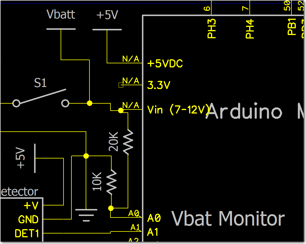
The next challenge was to reorganize and update the system schematic to reflect all the new inputs, outputs, and function blocks. The complete system schematic is shown below:
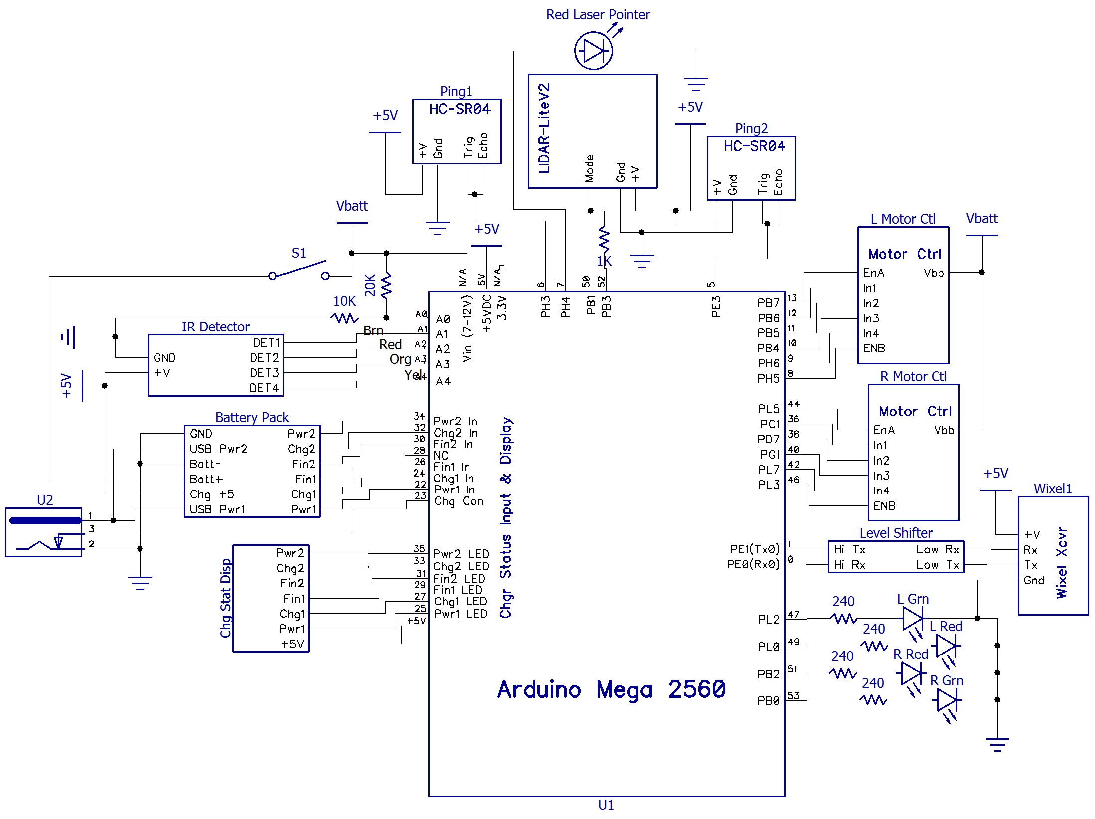
4WD Robot System Schematic with pin assignments as of 05 March 2017
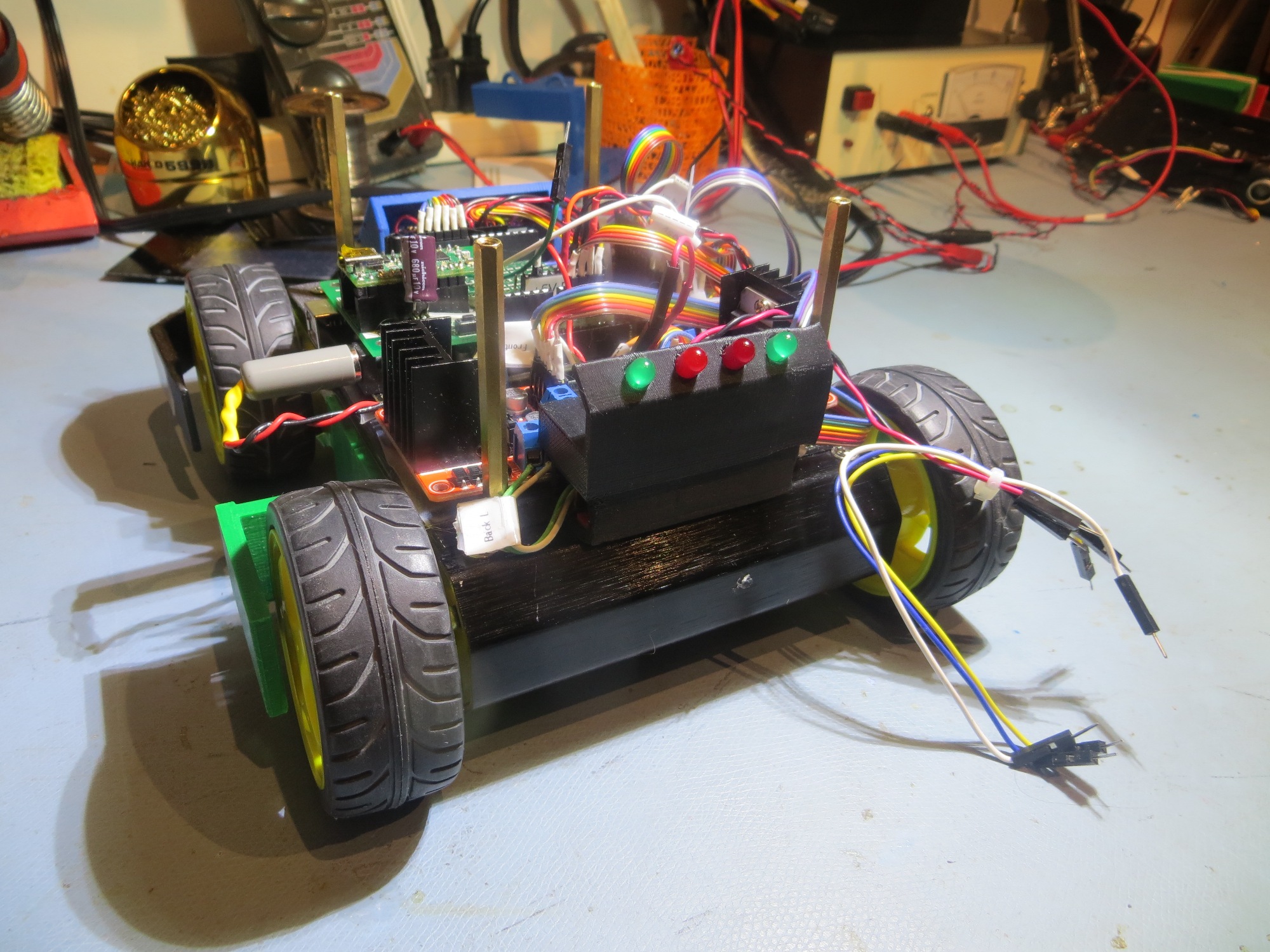
For completeness, I have included front, rear and both side views of Wall-E2 in its current state of construction. The new battery pack and associated charging electronics has been fully integrated into the internal volume, and all the charging-station related modules/electronics have also been mounted. The only thing missing physically at this point is the second deck with its two sonar ping sensors, the LIDAR forward distance sensor, and the forward red laser pointer
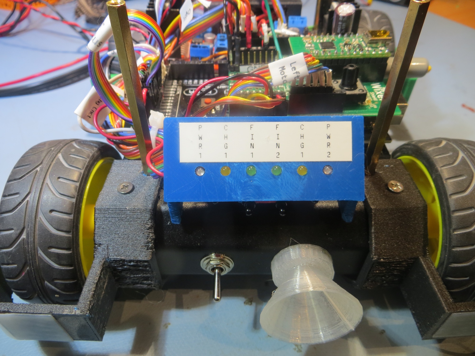
Front view showing charger jack coupler and new charge status display
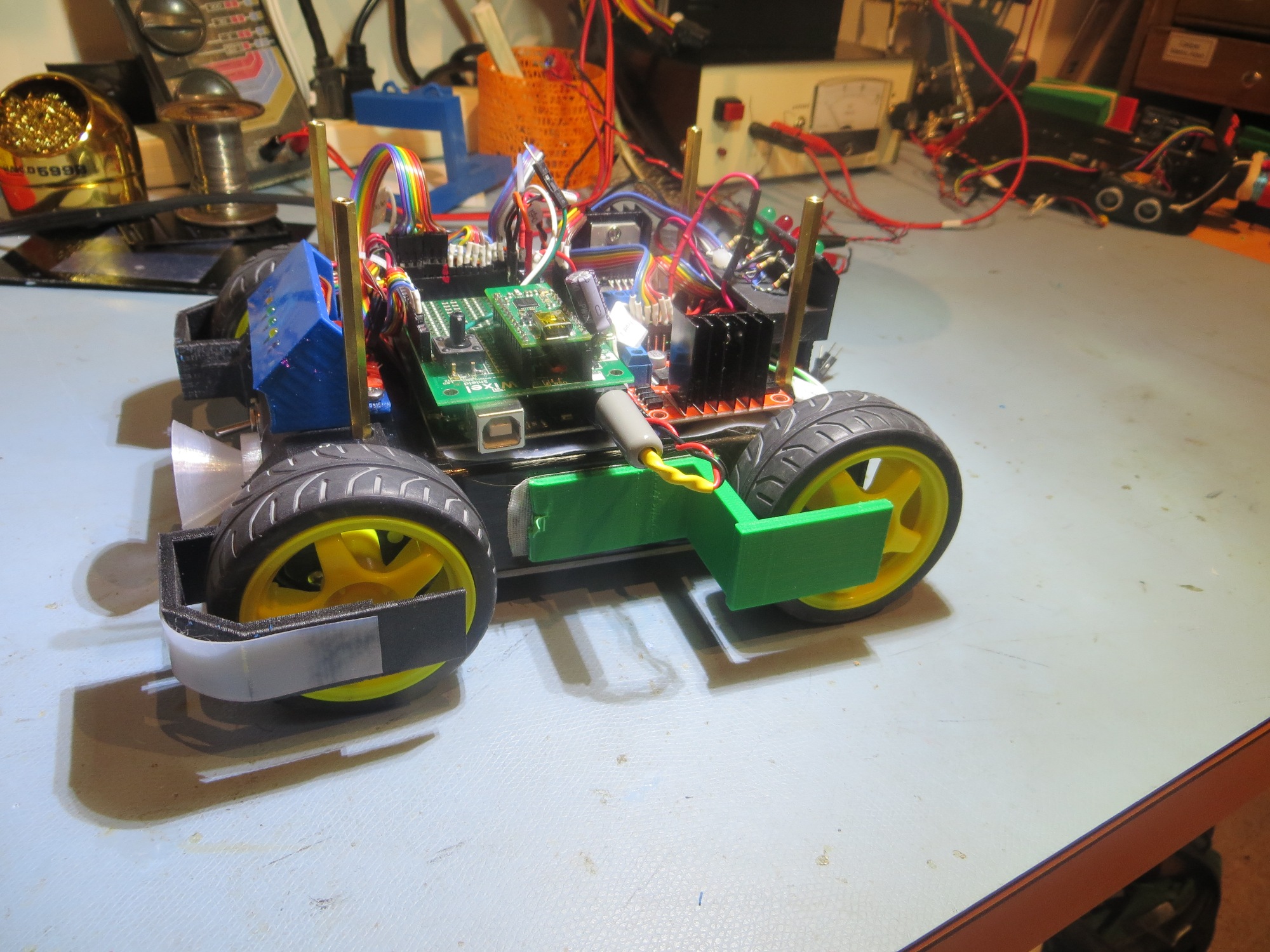
Left-side view. Nothing much has changed in this view
Rear view showing ‘taillight’ assembly. Loose cabling is for 2nd deck ping sensors
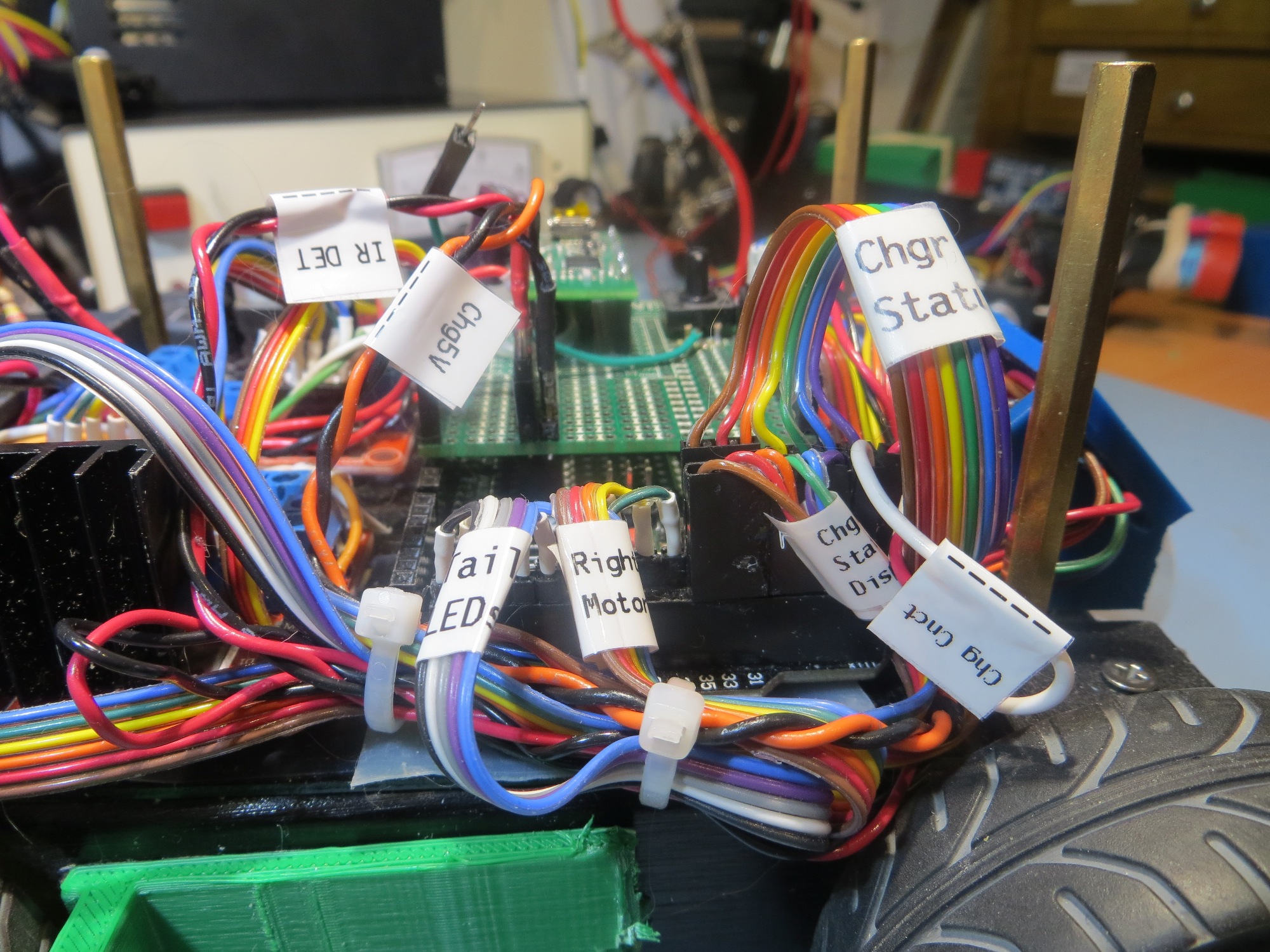
Right-side view showing some of the new cable bundles
Frank