Posted 18 Dec 2016
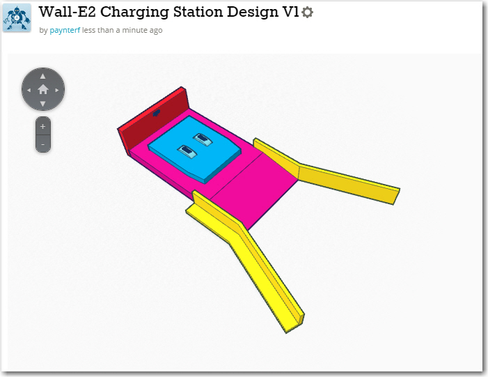
The new charging system for Wall-E2 consists of three major parts:
- The two 3.7V Li-Ion battery packs and battery chargers (one charger for each battery pack)
- The contact array that connects the charging platform to the chargers.
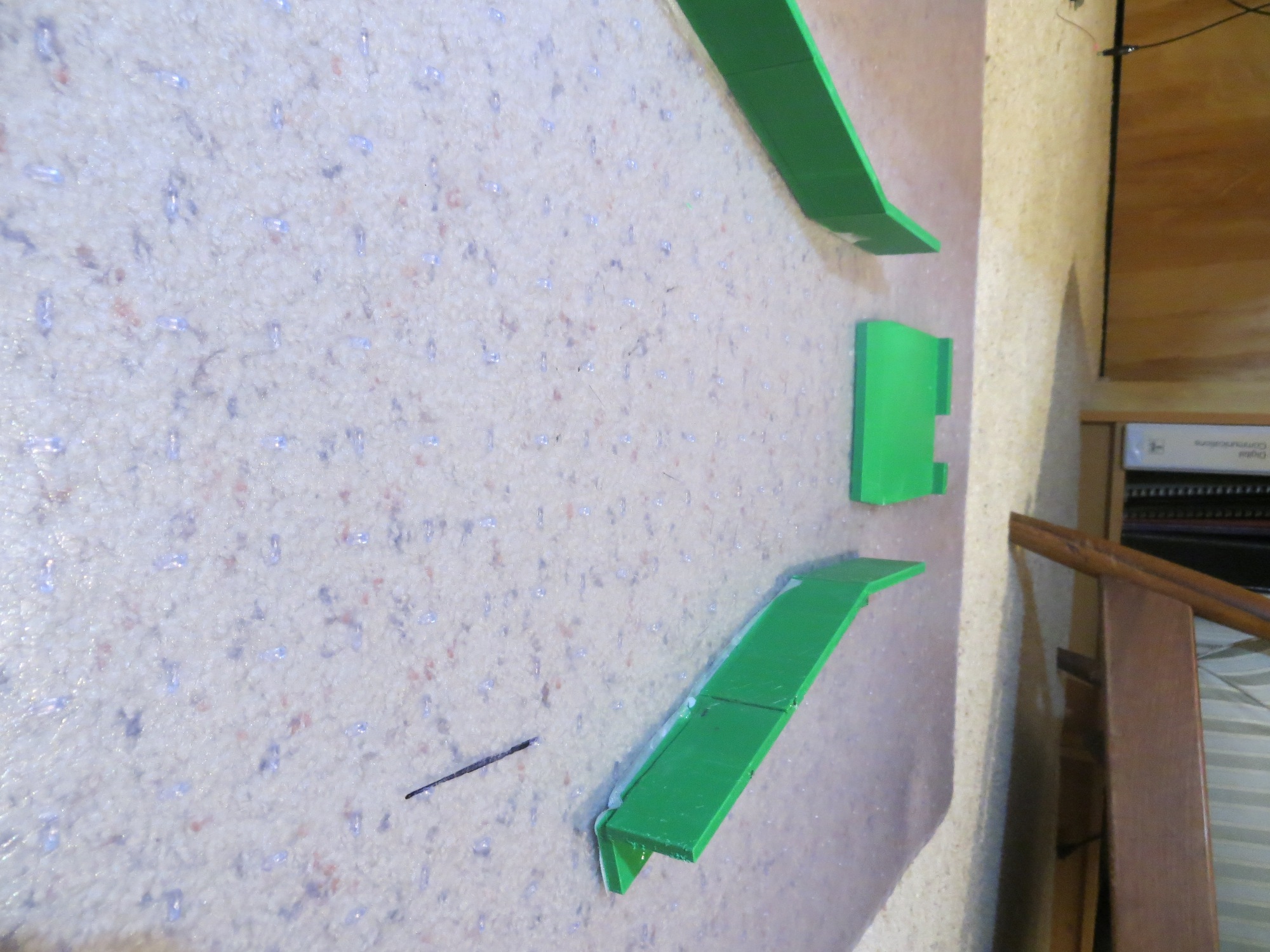
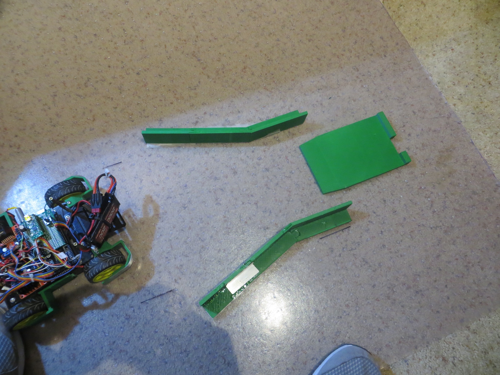
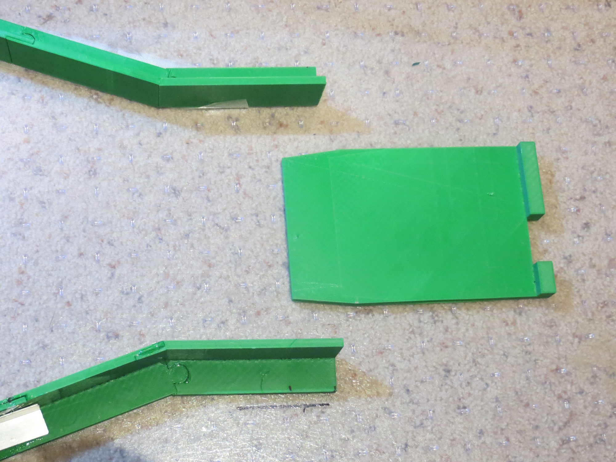
- The charging platform and charging power supply
I have spent the few days or so working on the first two items above, building up the battery pack and charging circuit for Wall-E2, and working out the details of the contact array for connecting Wall-E2 to the charging platform.
Charging Module:
This is actually the third time I have attempted a charging system for a 7.4V Li-Ion battery pack consisting of two 3.7V cells. The first one was for my original Wall-E, and it is still cooking along. The second one was for Wall-E2, and it didn’t go as well. After all the work of building up the module and tucking it into the robot, I discovered that the system just wasn’t robust enough for Wall-E2’s higher power requirements, so I wound up going with a high-current RC battery and an external charger. This wasn’t really satisfactory either, as the battery pack was just too big and awkward, and having to physically disconnect the pack from the robot to charge it was a real PITA. Plus, I still harbored the desire to make Wall-E2 more human-independent by giving it the capability of recharging itself. So I made another run at the dual-pack charging universe, and this time I found an article by the Adafruit guys about a ‘simple balance charger’ using two of their Li-Po chargers and a manual 3PDT switch. This article very closely matched the charger setup I had used previously, except for one extra pole on the switch. In the Adafruit circuit, this third pole was used to switch the positive side of the upper 3.7V pack from the load to the upper charger. My previous designs didn’t have this switch, and on closer examination, I realized that without this third pole, the upper charger might see the entire 7.4V on its output port – oops! The reason for this is that the chargers aren’t truly isolated from each other – they share a common ground, and when the circuit is in series (RUN) mode, the upper charger’s plus output is still tied to the upper battery’s positive terminal, while its negative output is still at ground. This puts the entire 7.4V across the upper charger – a BAD thing!
So, I needed a third pole, but although small 3PDT manual switches are easy to find, small/compact 3PDT relays are not. In my previous designs I had used the very nice Axicom V23105 2PDT telecom relay, but 3PDT relays in the same form factor were nowhere to be found – grrr! So eventually I decided to use two of the Axicom relays and gang the coils to get a 4PDT relay, one pole of which would go unused. Also, learning from previous mistakes, I made sure I could easily remove/replace the battery packs and the chargers if necessary. The final charger schematic is shown below, along with some images of the finished charger module.
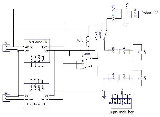
Dual cell balance charger. Note the two Axicom relays ganged to form the required 3PDT switch
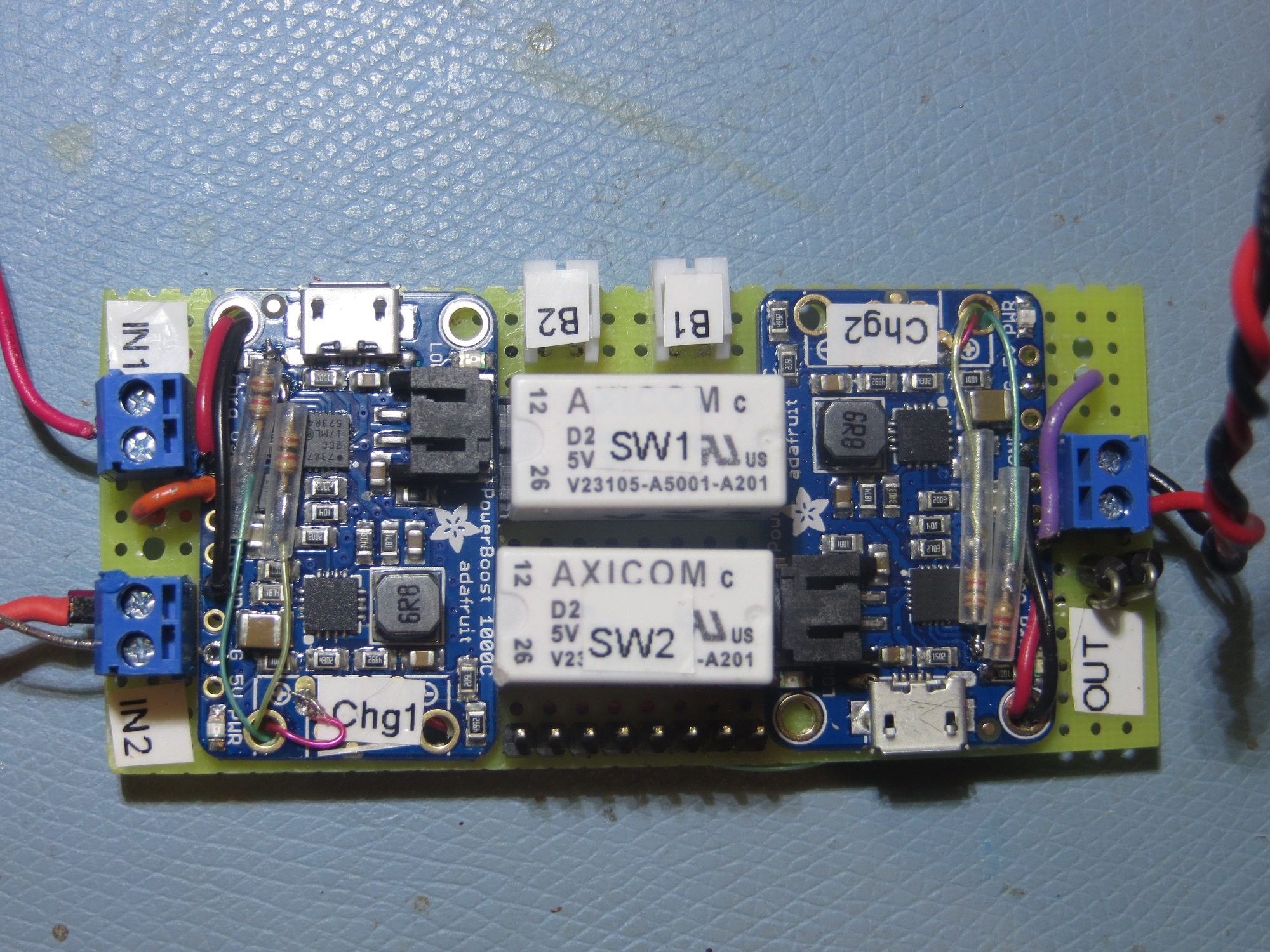
Closeup of the completed charging module. Note the two Axicom relays used to implement a 3PDT switch
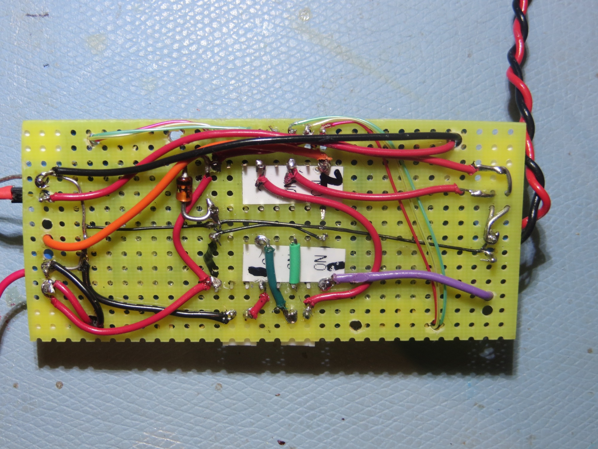
bottom wiring layer of charging module
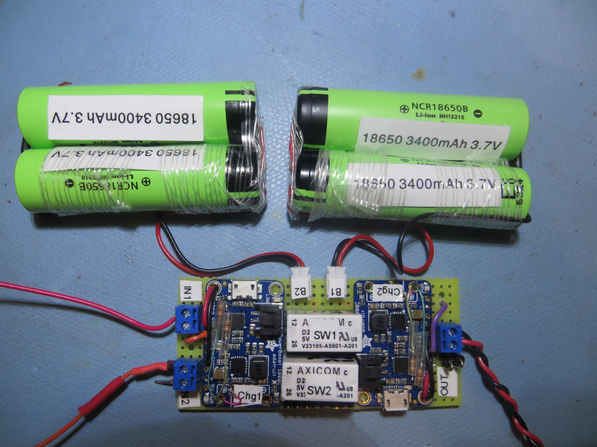
Finished charging module connected to two 2-cell 3.7V battery packs
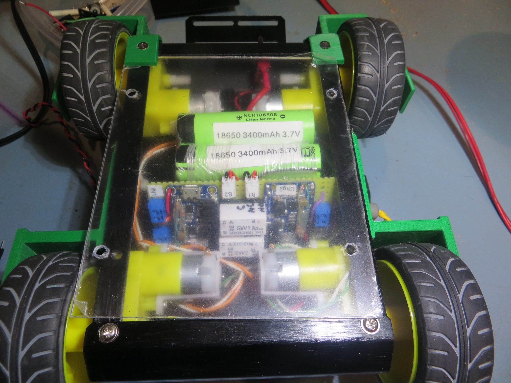
Bottom rear view of 4WD robot showing battery packs and charging module
Signal/Power Contact Array
The next challenge was to figure out how to connect the robot to the charging station. In addition to supplying +5V to the two chargers, I wanted to bring out the power, charging and charge-completed status signals from both. This requires a total of 8 contacts ( 6 status signal lines, +5V in, and GND). I also decided to bring out the power line to the robot, for a total of 9 contacts. The idea here is to place contact strips on the bottom of the robot, which will make contact with spring-copper sliding contacts on the charging platform. I played with a number of contact layouts, but ultimately decided on a straight-line array of contacts due to space restrictions in the robot. In the image below, the contact array layout is shown, with the ‘Pwr LED2’ position partially implemented.
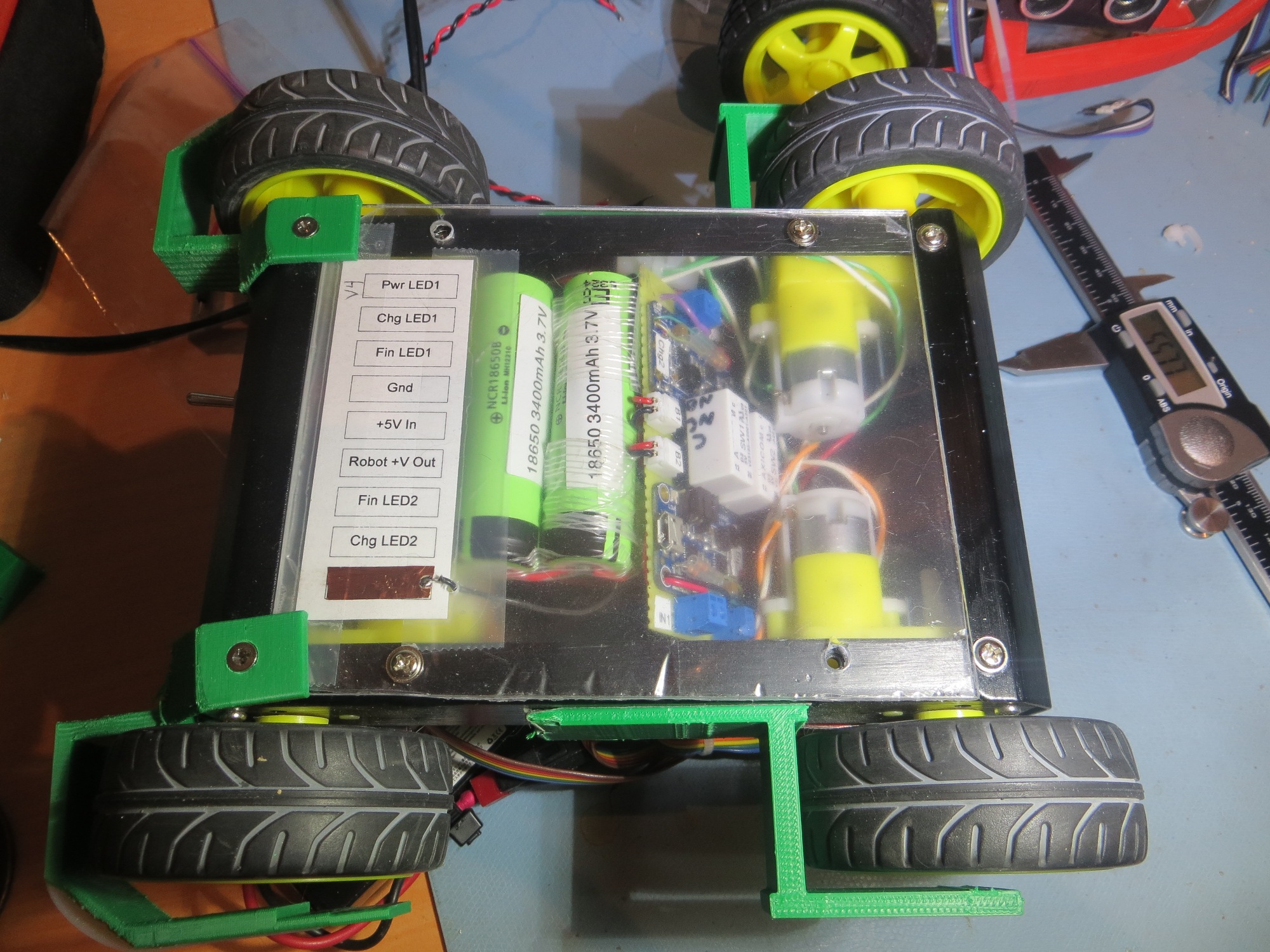
Bottom side view of 4WD robot showing contact array layout with the ‘Pwr LED2’ position partially implemented
Some time ago I purchased a length of beryllium-copper finger stock used for fabricating EMI gaskets, with the intention of using the individual fingers as contacts for the charging station. In order to do this, I needed a way of capturing each finger in the top surface of the charging station. I went through several iterations as shown below
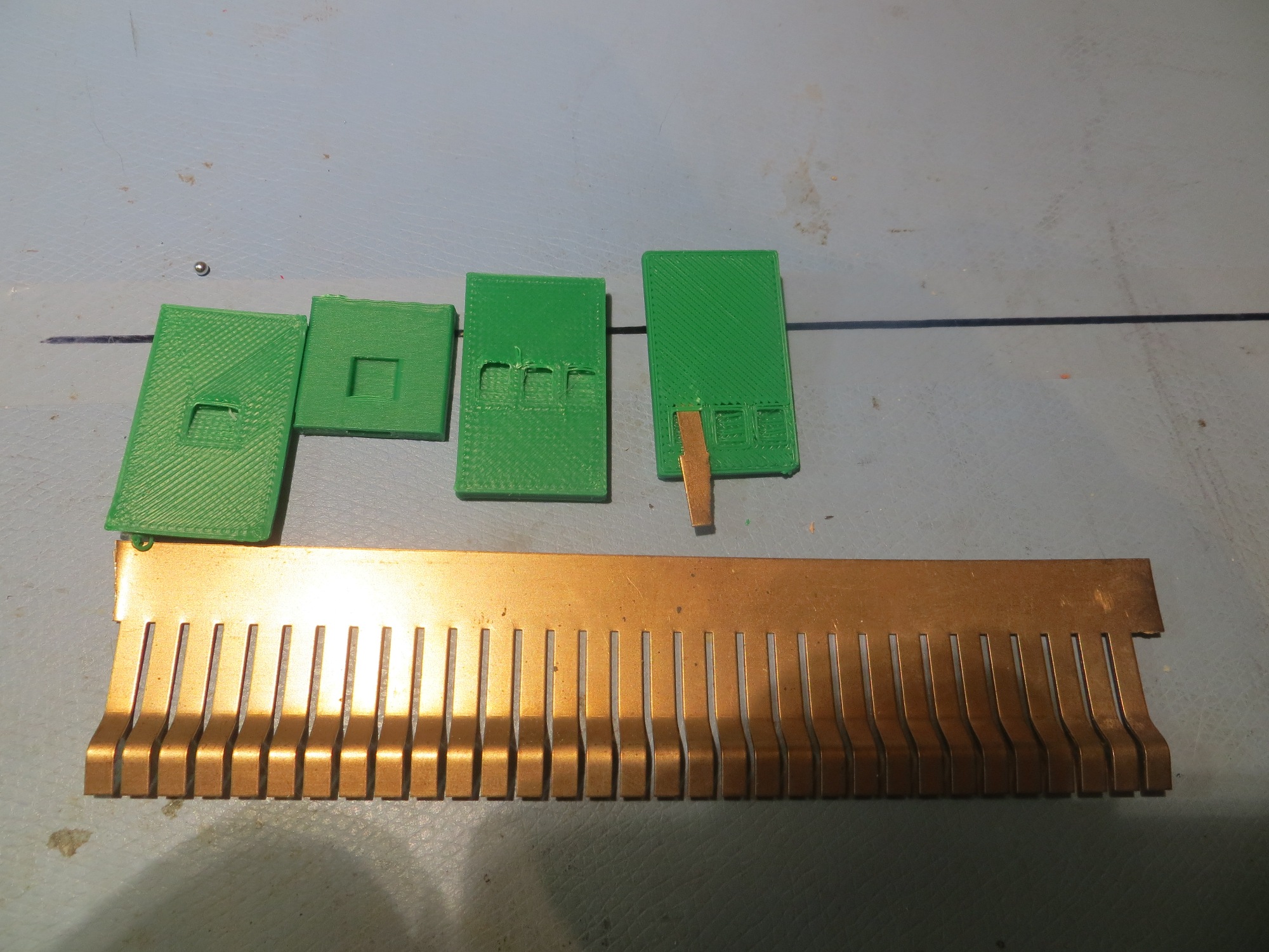
After playing around a bit with a single contact finger and the contact arrangement shown above, I realized that a small misalignment between the robot and the charging platform could cause a finger to bridge two contacts or even connect with the adjacent circuit. So, I went back to Visio and redesigned the contact layout, as shown below
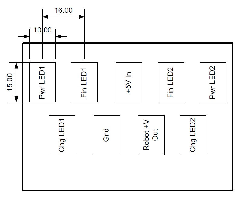
two-row contact layout. Contacts are 15x10mm with 16mm center-center spacing
As shown in the following photos, this is a much more robust arrangement in terms of contact mis-alignment protection, at the cost of taking up more space on the bottom of the robot

Contacts just prior to engaging
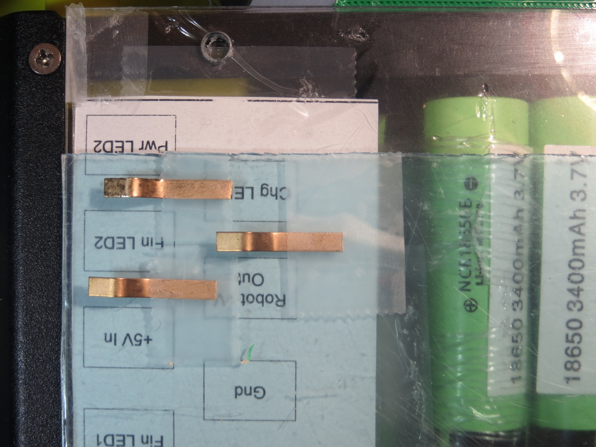
Contacts mis-aligned low
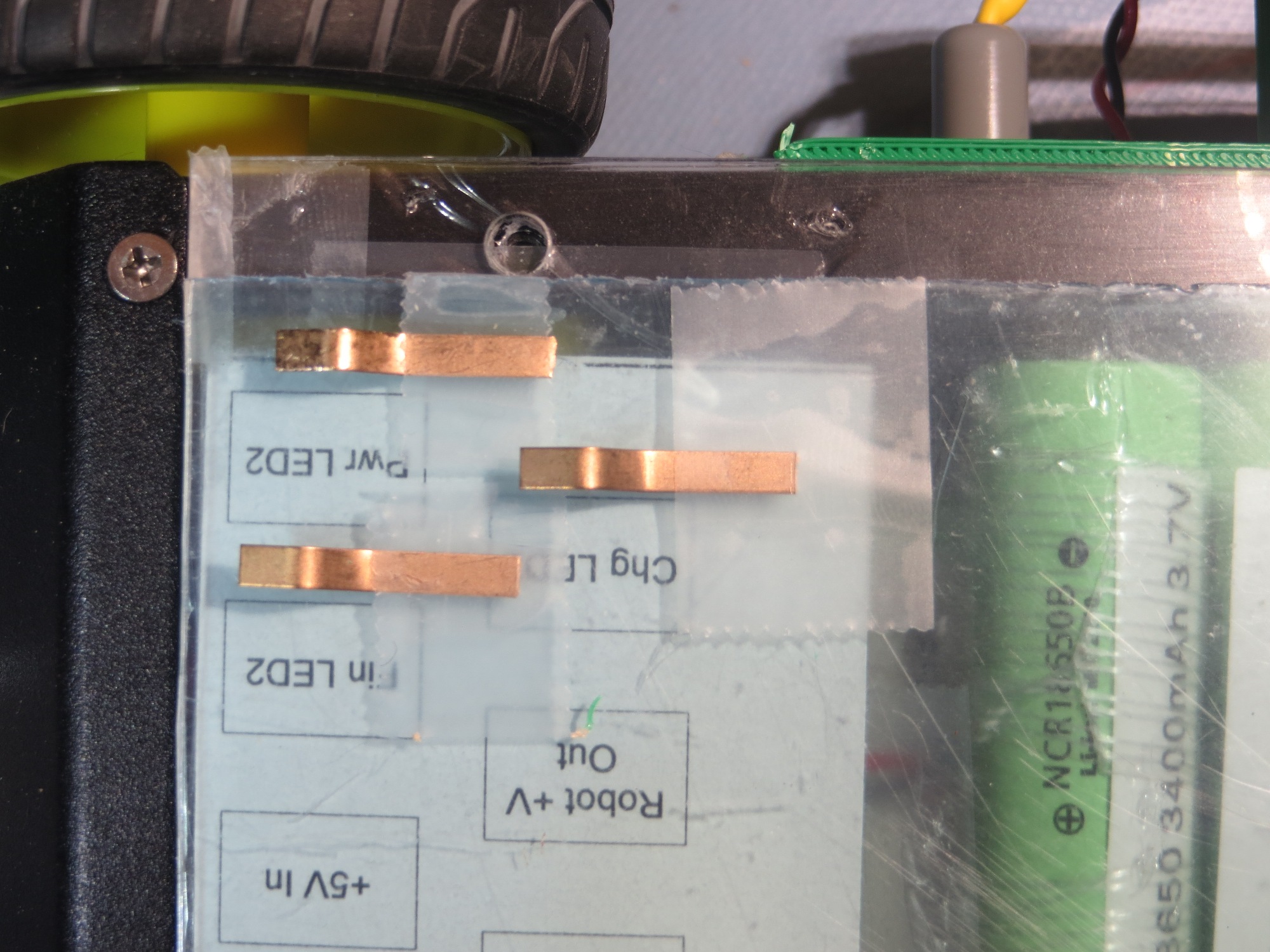
Contacts mis-aligned high
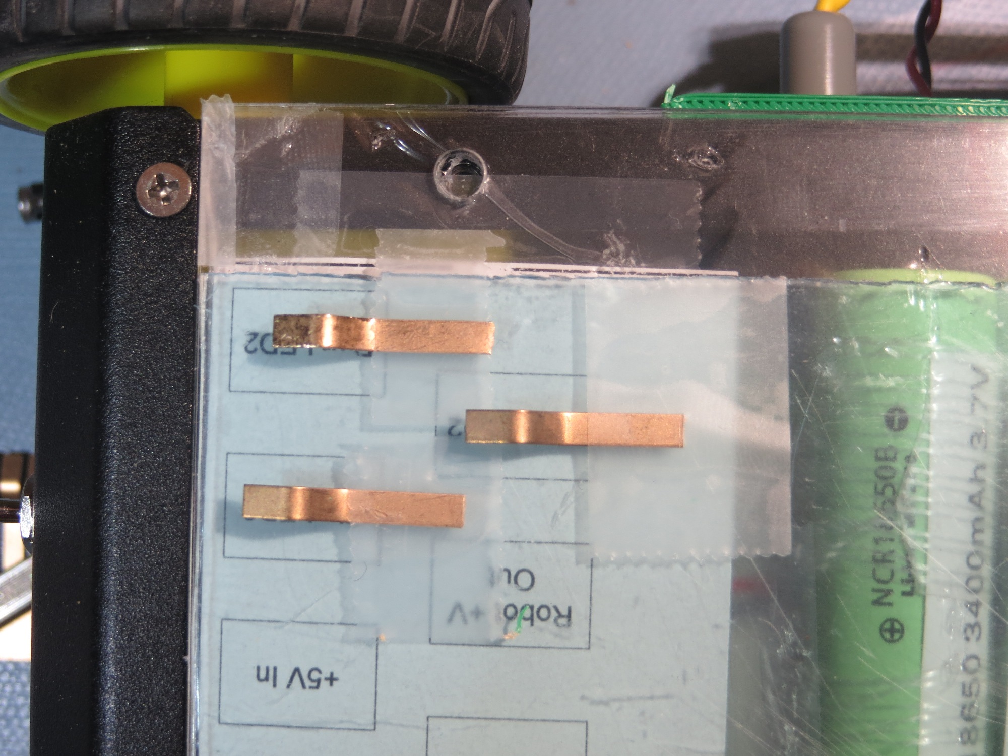
Contacts in the fully engaged position
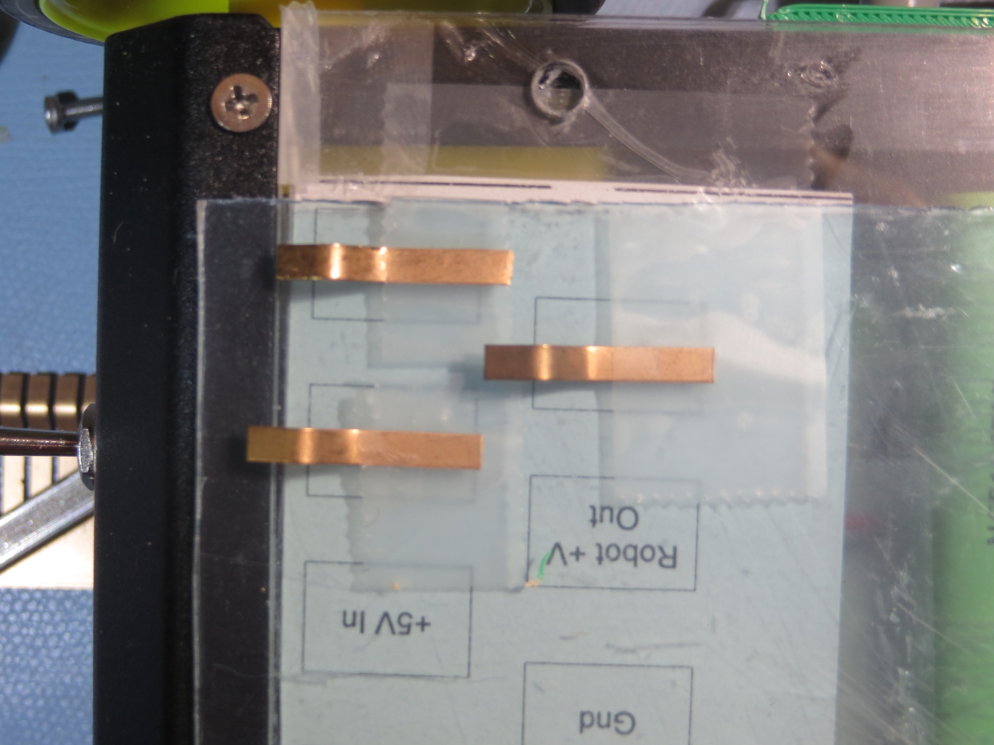
Contacts just before engaging
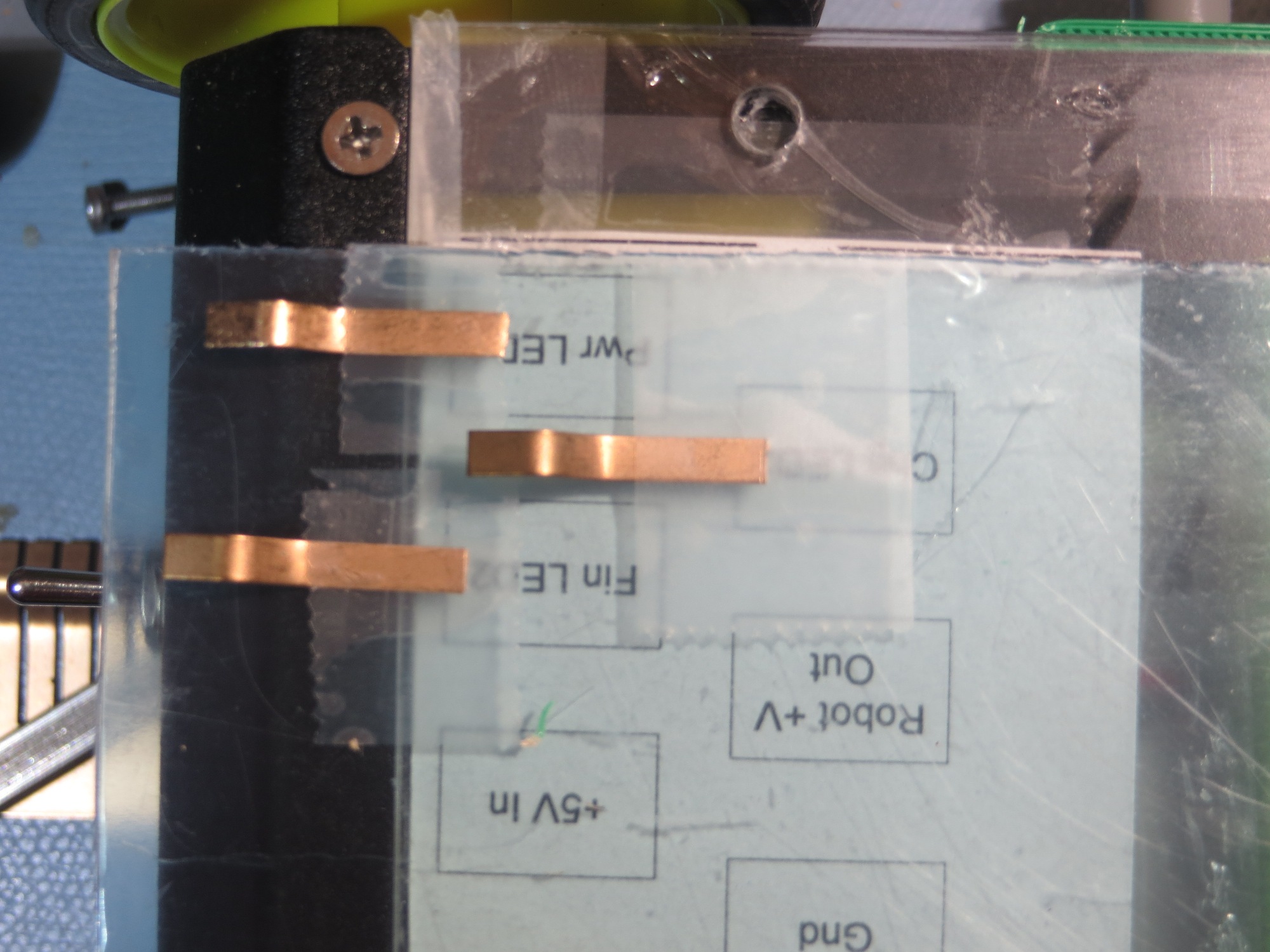
Contacts well before engaging
With the above arrangement, there is basically no possibility of a contact finger bridging the gap between two contacts, and even drastic mis-registration of the robot onto the platform will result in correct contact engagement. That’s my story, and I’m sticking to it! ;-).
Here’s a short video clip of a few simulated engagement/disengagement cycles
The next step was to fabricate the robot-bottom contacts from copper tape and wire them to the charging module. Here are some photos of the finished product.
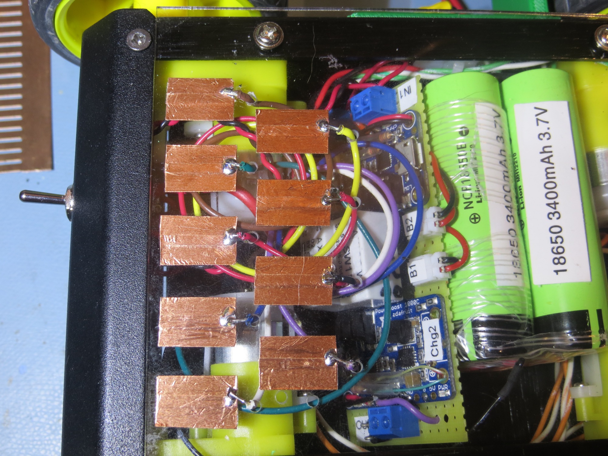
Interface contacts fabricated and wired to charging module
When I looked at the completed module, I recognized that I still had two issues remaining. The first and more important one is that I needed a strip of insulation to having the sliding contacts short to ground or each other as they moved across it on their way to their final destination. The second one was that it would be nice to label the contacts so that I wouldn’t have to trust my very untrustworthy memory. As I thought about this, it occurred to me that I could kill two birds with one stone by placing a label strip on the chassis, as shown below – cool huh!
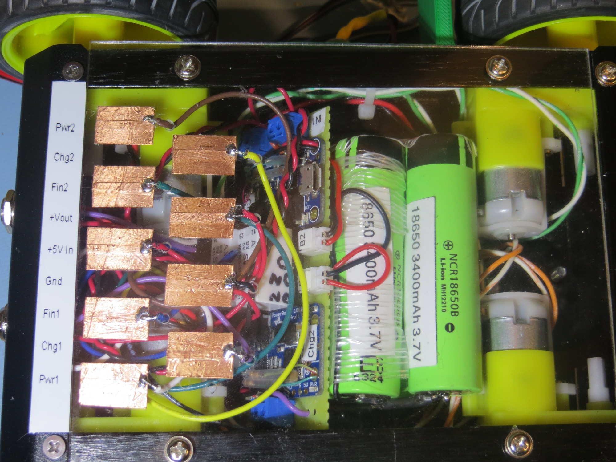
Added labelling to contact array. This was a ‘two-fer’ as it also prevents contact shorting to chassis
Frank
