Posted 19 November 2016
Well, as usual, things aren’t quite as simple as they seem, and the ’10 minutes, tops’ rule still applies (whenever someone says ’10 minutes, tops’, they are lying by at least one order of magnitude!). But, on the bright side, I really do understand PID control systems a lot better now (a low bar, as just the other day couldn’t remember what the ‘P’ in ‘PID’ stood for!), and I now think that WallE (and/or WallE2) has a pretty reasonable chance of homing in on an IR beacon with sufficient accuracy to be captured by a charging station setup.
In my last post on PID tuning, I had assumed that the PID compute engine normalized the tuning constants before doing the computation, and I decided I needed to check that assumption before continuing. When I looked into the actual code in the Arduino PID library, I found that this was not true – the PID compute engine does not normalize. It simply computes the PID expression:
output = kp * error + ITerm- kd * dInput;
where ITerm is ITerm+= (ki * error)
However, what this means is that my previous attempts to simplify the tuning problem by eliminating the I and D terms and just tuning the P term was doomed to failure – there was no way ‘do just P’ because the physical dynamics are too complex. The response curves of the IR detectors (shown below),
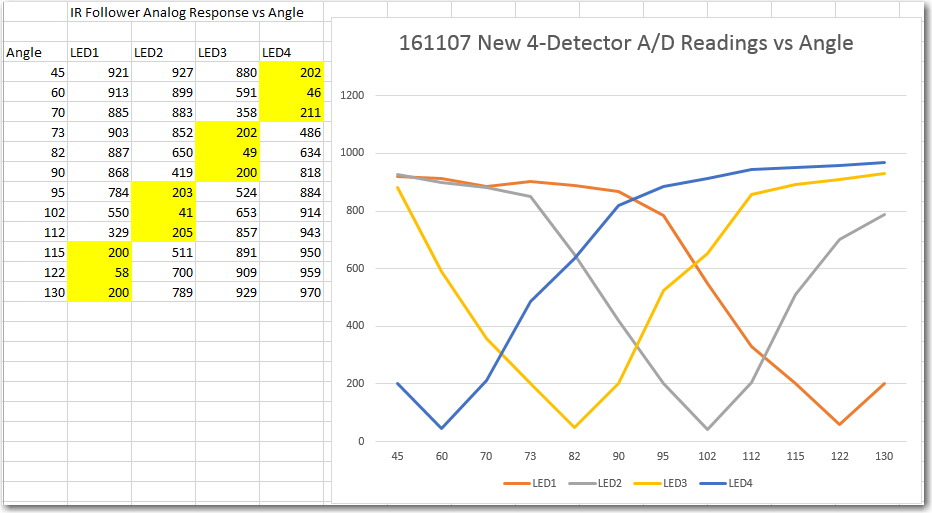
4-detector heading test results
combined with the physical dynamics of the robot itself, require more than just a proportional response to the error (the difference between the sums of the two left and two right detector readings) term. Ken suggested I could do this by using a pulse train (similar to PWM) for the motor drive signal, but I think that is equivalent to adding some ‘D’ to the PID tuning parameters.
In addition to the physical dynamics issues, there is also the problem of the detector response versus distance. At maximum detection range, all detector readings are near 1000, so the error term is very small, on the order of 10-50. However, as the robot gets closer to the emitter, that error term rapidly gets much larger, on the order of 500-900. This means that the PID tuning parameters appropriate for the ‘far’ case will be wildly inappropriate for the near case (another consequence of not normalizing the PID values internally).
In any case, after a loonnnggggg series of floor field tests, I think I have arrived at a reasonably effective homing algorithm. Instead of trying to modify the PID tuning parameters as the robot approaches the emitter, I found it more effective to keep the PID tuning parameters constant, and instead scale the PID input (error) signal in three steps; 1 (no scaling) for error term values below 200, 0.2 (divide by 5) for values between 200 & 500, and 0.1 (divide by 10) for values above 500. A representative set of data and some videos are shown below. The last video shows a ‘side capture’ scenario, where the robot approaches at right angles to the IR beam and successfully captures the beam and homes in on the emitter.
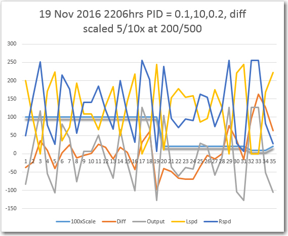
Typical run with 1/5/10x scaling as emitter is approached. Scaling term is shown here at 100x for clarity
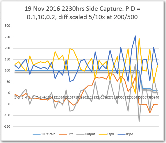
Side capture scenario. Scaling term is shown 100x for clarity
So, at this point I’m convinced that the PID/input scaling arrangement will work, and that I can get WallE2 to home in on an IR beacon. The next challenge will be to integrate the IR homing function with the normal wall-following function, and to design/fabricate the charging station itself. Stay tuned! ;-).
Frank
Pingback: Wall-E2 Charging Station Design, Part I - Paynter's Palace
Pingback: Charging Station Design, Part X - Paynter's Palace
Pingback: Charging Station Design, Part XI - PID Tuning - Paynter's Palace