Posted 13 November 2016
After reviewing the benchtop field test results, I decided to try implementing a PID (Proportional/Integral/Derivative) controller for WallE. There is a quite nice PID library in the Arduino eco-system, thanks to Brett Beauregard (br3ttb@gmail.com), and I already had it installed on my system from a previous project. Getting it implemented for my project wasn’t too much trouble, but of course the issue with PID controllers is getting it ‘tuned’ (i.e. finding the values for P, I, & D) for the particular physical setup.
For my 4-detector system, I used the difference between the sum of the two left detector values and the sum of the two right detector values as the input to the PID controller, and chose a setpoint of zero – i.e. the idea was to drive the difference in the detector sums to zero, which should mean that the robot is pointed directly at the IR source. The output from the controller was used in a differential fashion to drive the motors; the output was fed directly to the right motor driver as a 0-255 PWM value, and the left motor drive value was 255-Output.
The first step was to set the PID values appropriately, and I had absolutely no idea how to do that – so I just started with the default values of 2, 5, and 1 for the P, I, and D values respectively, and DIRECT for the sense indicator. Then I ran some tests on my 24″ benchtop range to see what happened. Of course the first thing that happened is that WallE immediately departed from the plan and dove off the benchtop (I caught it before it hit the ground). This was fixed by changing the PID output sense from ‘DIRECT’ to ‘REVERSE’, and I started getting some successful runs.
The next step was to make some more realistic homing tests, and for this I moved the IR emitter from my benchtop down to the floor at one end of my bench, and started WallE from the other end – about 1.5 m away. I made a number of runs, changing the PID tuning parameters to try and find a reasonable arrangement. After some playing around and some more Googling, I arrived at a tentative arrangement with a dual parameter set – one for small left/right differential excursions, and another for large excursions. As the following video shows, WallE successfully homed in on the IR emitter.
I also captured telemetry from the run, and plotted the left/right differential in Excel, as shown below:
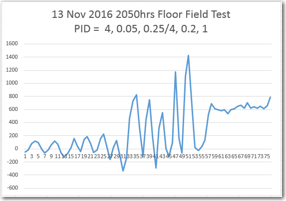
Left/Right differential from 13 November floor field test
In the above plot, a marked difference can be seen between the differential behavior up to about point 33, and the differential between 33 and the end of the run at about 55 (the data after 55 was captured after I stopped the robot and picked it up, and before I got it shut down). I believe this change is due to my use of two different values for I & D, triggered when the differential became greater than 200 (due to increased received signal strength at the detectors, and possibly due to higher angle deviation as the robot neared the emitter). More testing will be required to determine the best set of parameters for the 3-wheel WallE robot.
Once I get comfortable with IR homing using WallE, I plan to transition the capability to WallE2, the 4WD robot. This will probably require significant re-tuning, as WallE2’s steering dynamics are quite different.
Stay tuned!
Frank