Posted 11/12/16
In my last post on this subject, I demonstrated a 4-detector IR-homing setup that I constructed using some nice OSRAM IR phototransistors. The next step is to mount this module on my robot to see how/if it can be used to home in on an IR source. Rather than try to integrated it onto my already crowded 4WD WallE2 robot, I decided to see if I could resurrect my original 3-wheel WallE robot and use it as a test platform.
As I mentioned previously, I had found that the OSRAM phototransistors (in stark contrast to the OSEPP 6-detector IR Follower module) were not at all sensitive to my overhead LED lighting, eliminating the need for a sunshade entirely. This made the mounting chore a lot easier, and by happy circumstance, the mounting holes in the 4-detector module matched up with the front caster wheel mounting holes on the original robot. So, mounting turned out to be just a matter of exchanging the original 3x6mm mounting screws with 3x12s and adding 1/8″ standoffs, as shown in the following photos.
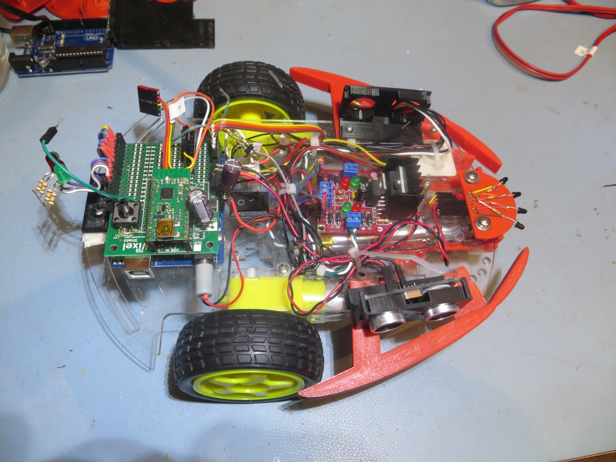
Original 3-wheel WallE, with 4-detector module mounted at the front
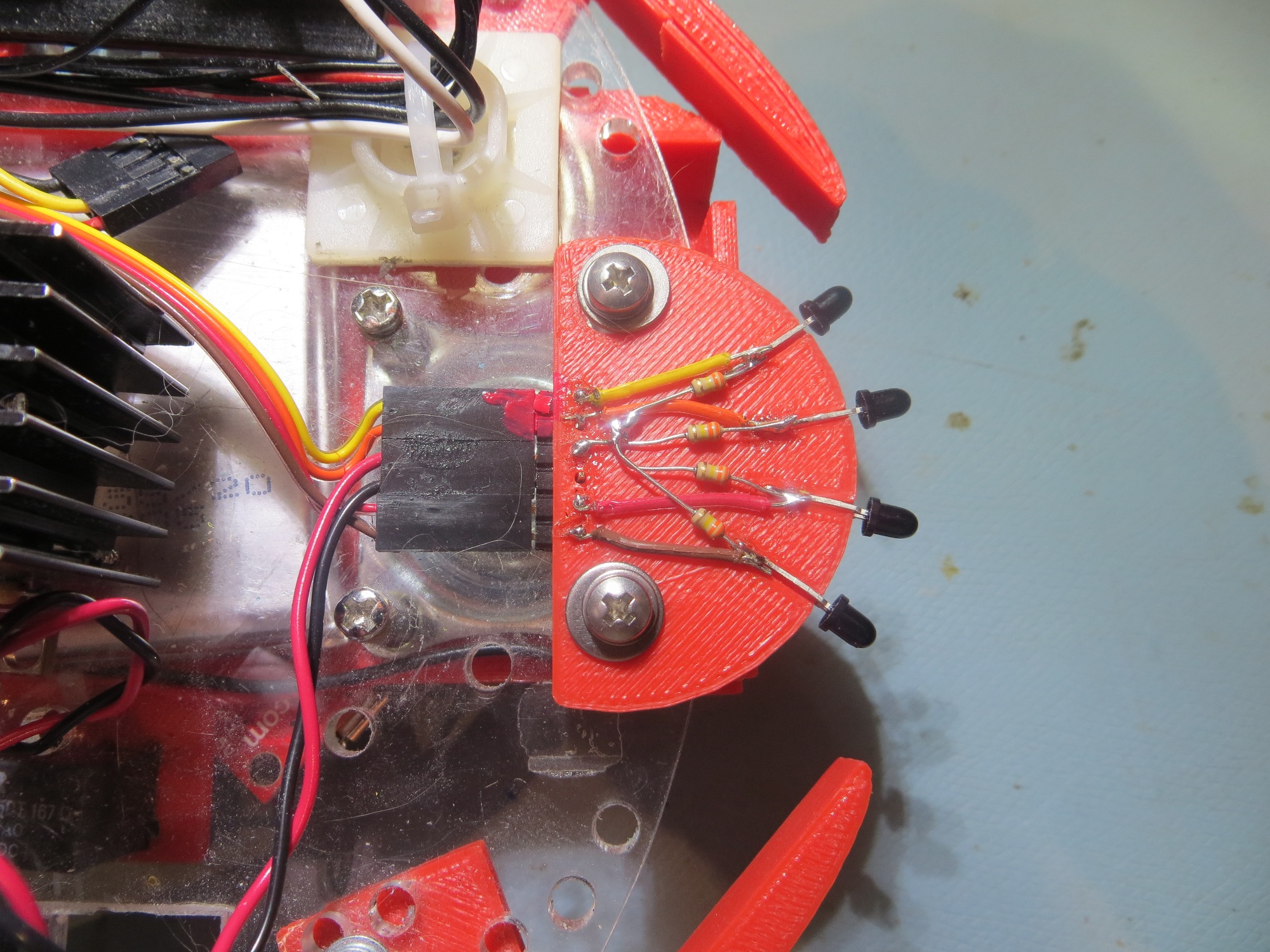
Closeup of the 4-detector module mount
Next, I went back through all my old Arduino code projects and found the latest version of my 3-wheel robot code (I did mention that I never throw anything away, didn’t I?). Then I copied the relevant motor management code from this project into the project I had already started for testing the 4-detector module, and ran a couple of benchtop field tests. For the tests, the robot started out about 75-80cm from the IR emitter, and (after some tweaking of error feedback factors) was able to home in on the emitter, as shown in the video clip below
I ran this test several times, and the robot was able to home in on (and actually strike) the IR emitter. A representative final position is shown in the following photo
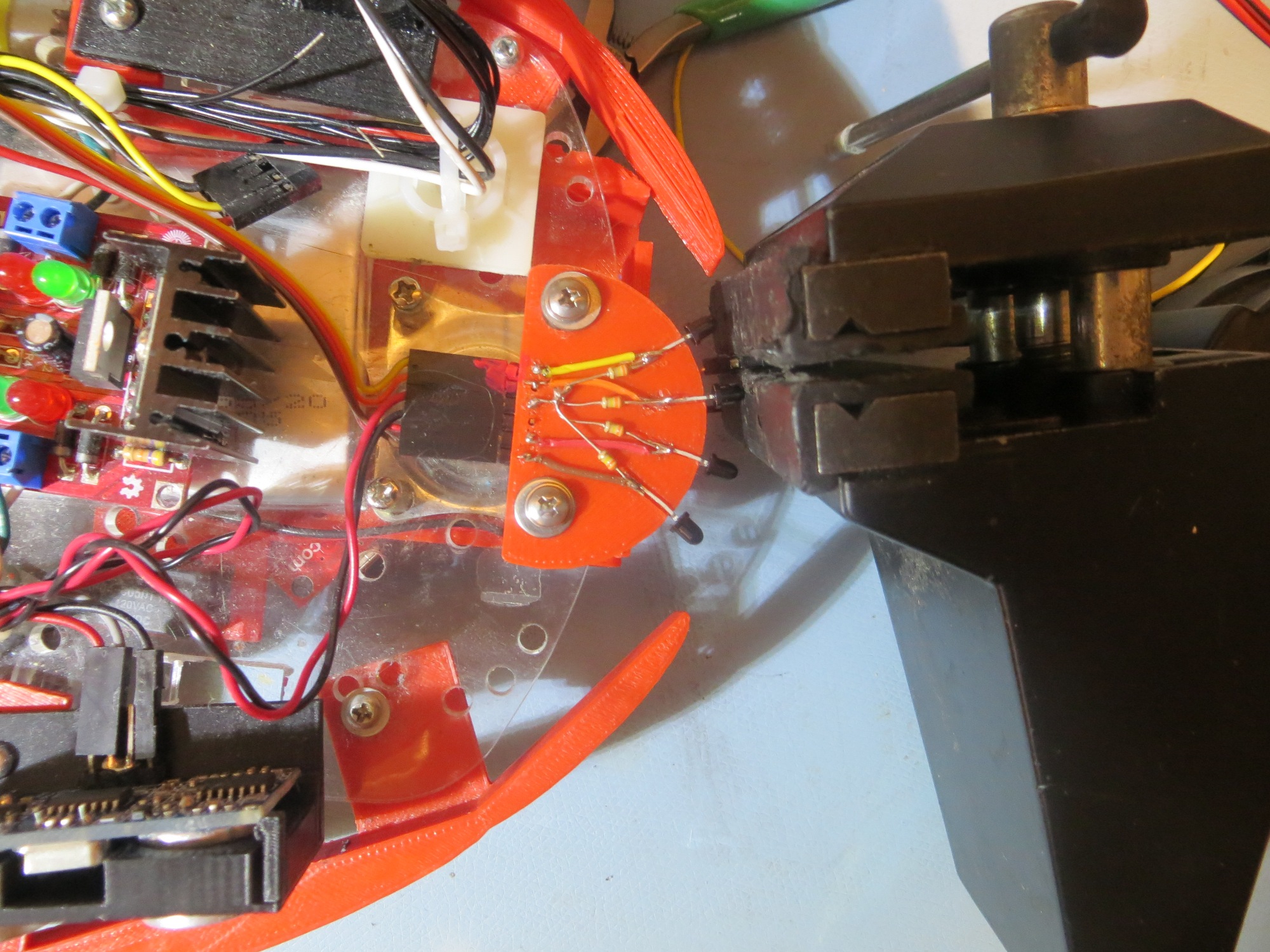
Final position after IR homing run. Note that the IR detector module actually struck (and bent) the IR emitter diode.
All in all, I think the ‘benchtop’ field testing was a qualified success. I wasn’t particularly ecstatic about the back-and-forth wandering of the robot as it tracked, but it certainly got the job done (or at least I thought it did until I looked at the actual tracking data as shown below). As the plot below shows, the left/right differential value appears to be growing larger in each cycle, until the robot ran into the IR LED at about point 82. This may well be due to my artificially limiting the max differential motor speed value (to less than 1/2 max speed) to keep the robot on the bench top, or possibly due to the positive feedback effect of the castering nosewheel. Remains to be seen.
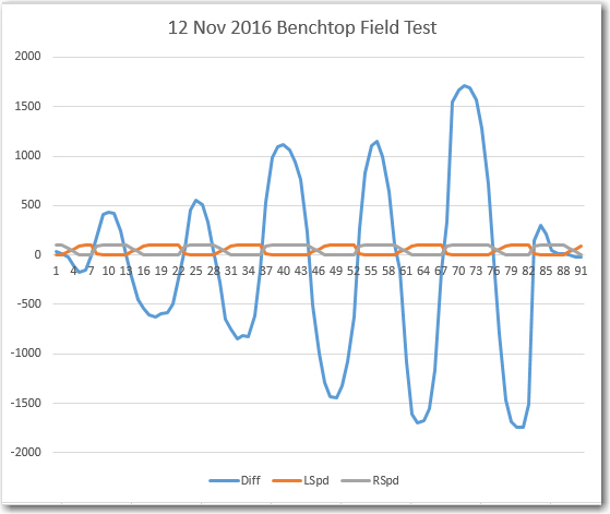
left/right Differential (Diff) and Left/Right motor speed values vs time for the 12 Nov 2016 Field Test
It remains to be seen whether or not the castering front wheel contributed to the ‘hunting’ behavior, and/or whether a different selection of error feedback factors would do any better. Suffice it to say, however, that the tests were certainly successful enough to encourage me to continue this line of development.
Next steps might be to set up a longer range field test, and maybe to set up a situation where the robot has to transition from wall following to IR homing behavior.
Stay tuned!
Pingback: Charging Station System Integration – Part II - Paynter's Palace