Posted 21 November 2016
Currently Wall-E2 is powered by a 2-cell LIPO 2000maH, 20C RC battery as shown below.
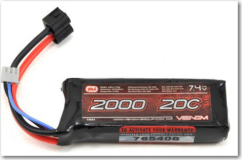
Current Wall-E2 battery pack
The charger I use is a X-Charger C6 model, which works great, except it has to be manually connected to the main T-connector, and manually started using front-panel pushbuttons.
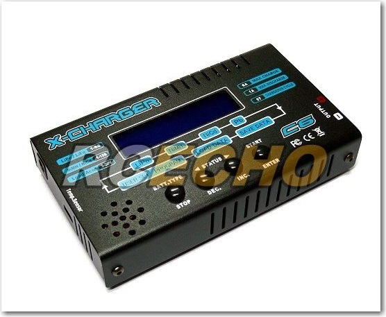
LIPO Battery Charger
For my planned charging station, I need a charger that can be automatically activated, either by simply driving Wall-E2 up onto the charging platform, or by computer control (Arduino or some such controller). After Googling around for a while, I thought I was pretty much going to be forced to roll my own high-rate 2-cell charger, as I couldn’t find anything like the XCharger above but with a computer control option. Then, in an uncommon burst of inspiration, I realized I could use the balance connectors associated with all these high-rate packs to charge both cells in parallel, using any one of the many popular computer-controllable single-cell LiOn/LiPO chargers, like this one from Adafruit, shown below:
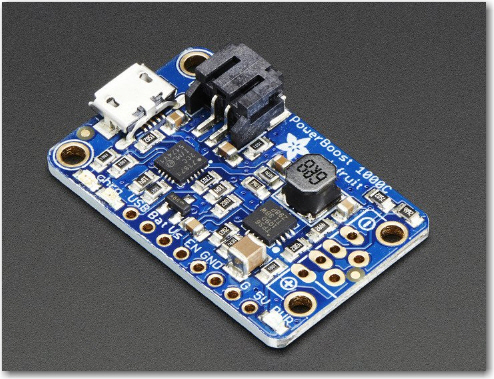
Adafruit PowerBoost 1000 LiOn/LiPo charger
And some LiPo batteries to go along with it, like these
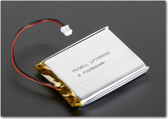
Adafruit 3.7V 2500mAh LiPo battery
After thinking about this for a while, it now occurs to me that I might wind up with something very close to the setup I had in my original Wall-E wall following robot, with two 3.7V single-cell batteries and two charging modules on the robot, with a DPDT relay to switch the cells from series connection (to run the robot) and independent (for charging).
The issue is how to charge the battery pack; I can charge a 2-cell pack with my XCharger, but that requires manual interaction each time, and the XCharger is physically large. Physical size isn’t a huge problem for the fixed-position charging station, but the manual interaction issue is a deal-breaker. There are some designs for DIY multiple-cell LiPo chargers out there, but I don’t want my wall-following robot project to metastasize into a LiPo charger design project (I already have enough alligators in this swamp – no need to add more!). So, since really nice single-cell charging modules are already available, why not use them? As a bonus, the chargers can be mounted on the robot within easy reach of the standard 2-pin JST-PH connectors, so all I need on the charging station side is +5V DC power, which I can apply through the planned spring-loaded connectors on the bottom of the robot. As an added bonus, I might be able to fit the entire assembly into the bottom cavity along with the motors – this would free up lots of space and dramatically simplify the currently somewhat messy wiring layout
The following images shows the Wall-E wiring diagram from about 18 months ago
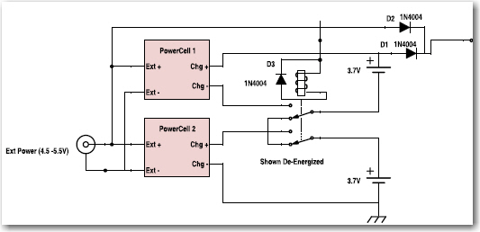
Wall-E charging setup from early 2015
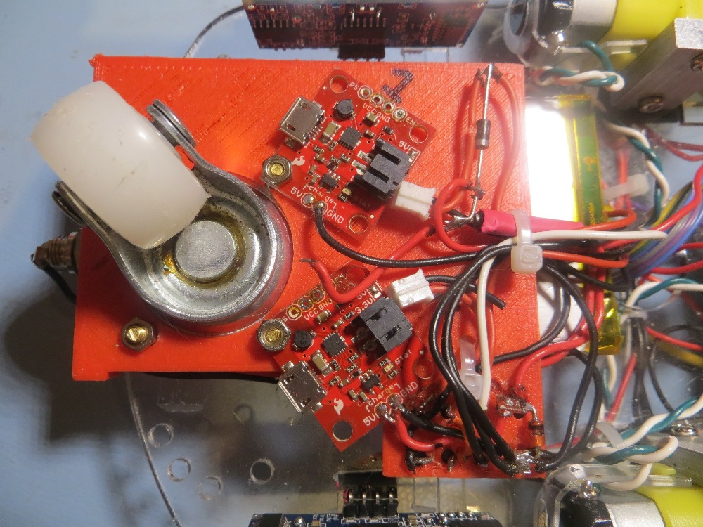
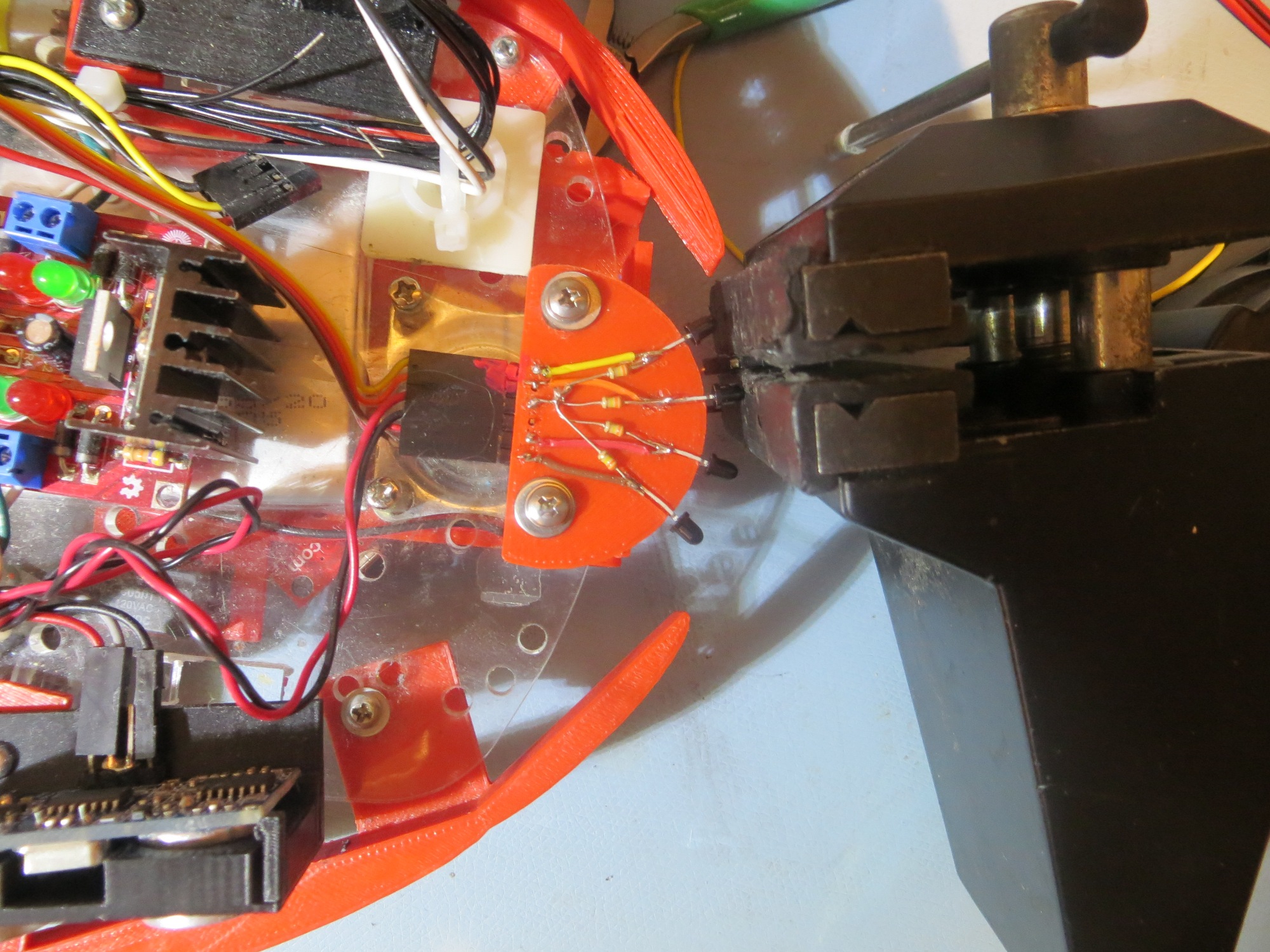
Original Wall-E battery charger and relay installation. Relay is at bottom right corner of the photo
The only difference between the above setup and my planned one for Wall-E2 is the batteries themselves are 2500mAh instead of 2000, and the charging modules are a heavier-duty type.
Stay tuned!
Frank