Posted 22 October, 2016
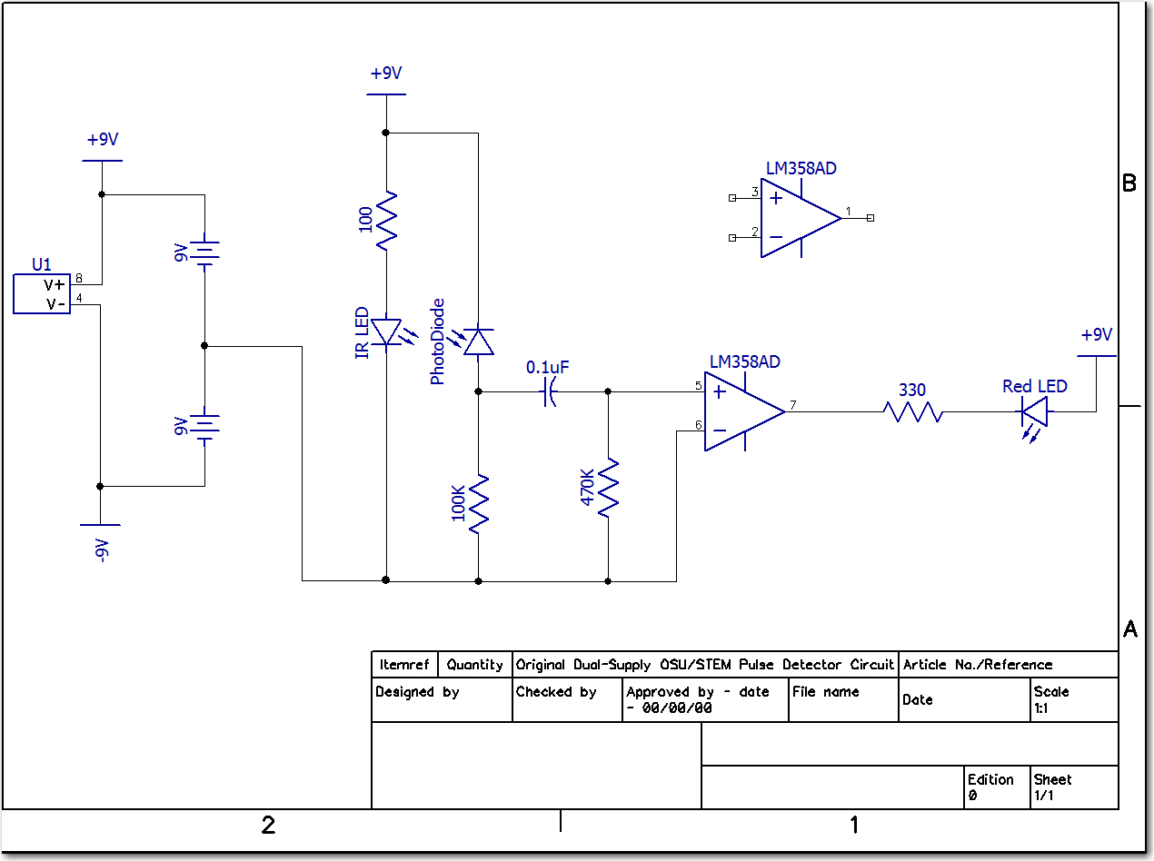
In my last post on this subject, I discussed a modification to the OSU STEM Outreach’s Pulse Detector schematic to eliminate the dual 9V battery supply in favor of a single one, taking advantage of the LM358 op-amp’s single supply operation capability. However, before actually recommending that the new arrangement be adopted, I wanted to make sure that it would work properly with the OXO ‘Soft-Clip’ finger clip module instead of the one I created for testing in my lab. It should work, but as a long-time engineer I have been bitten more than once by the difference between should and would! ;-).
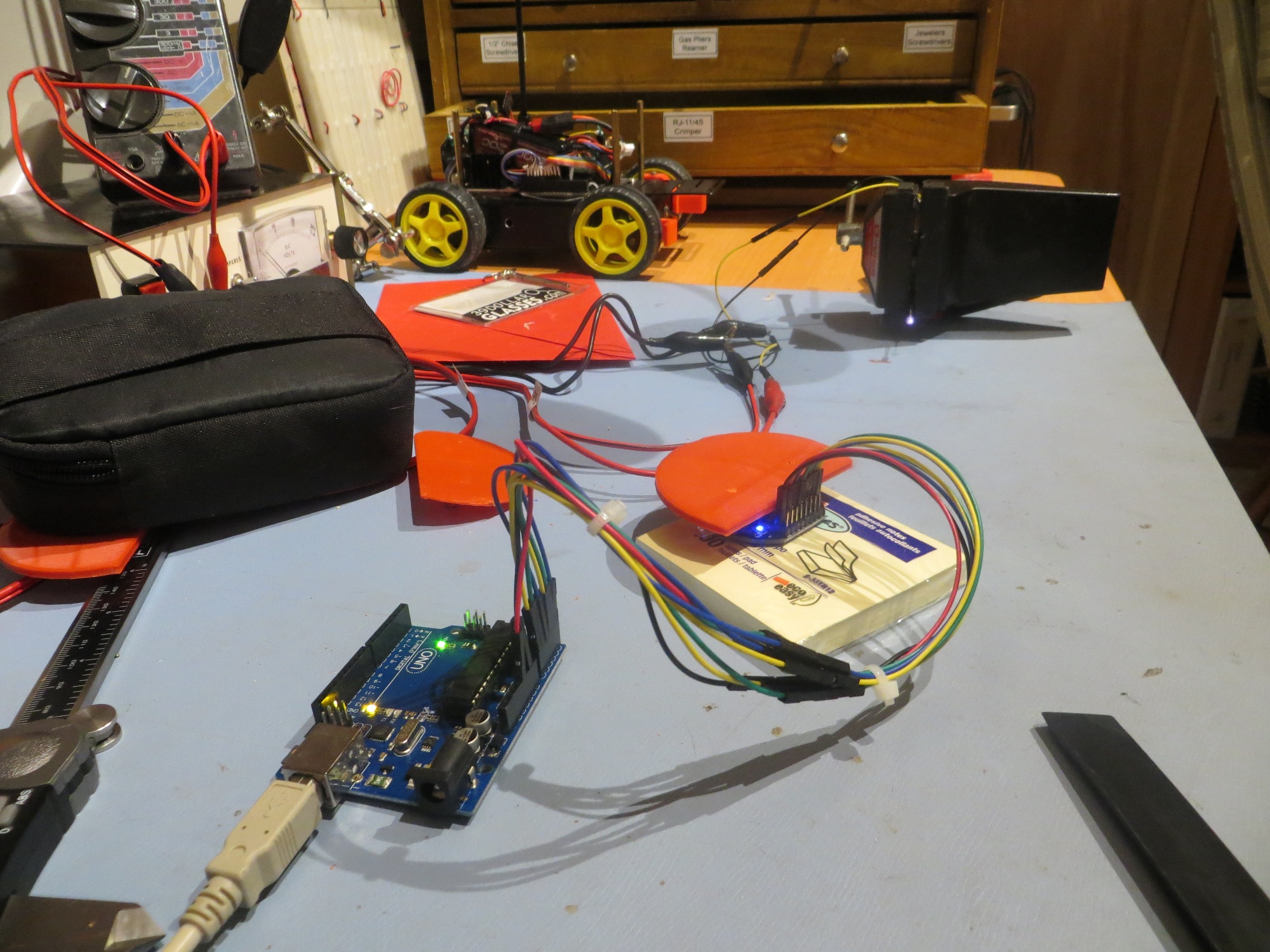
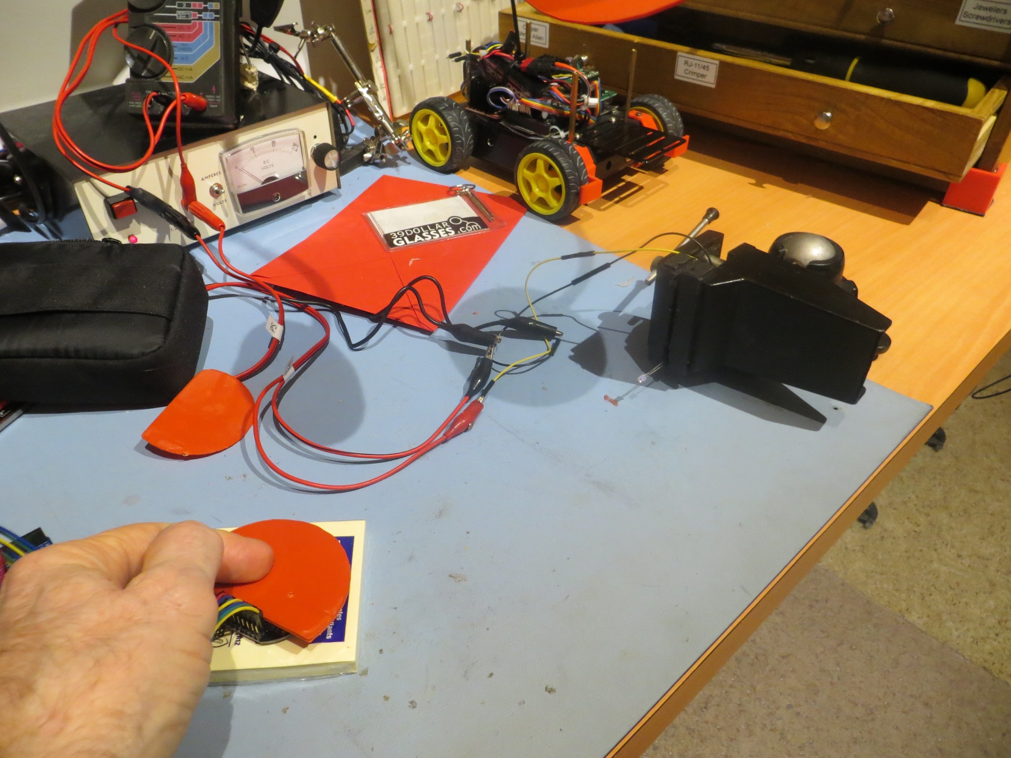
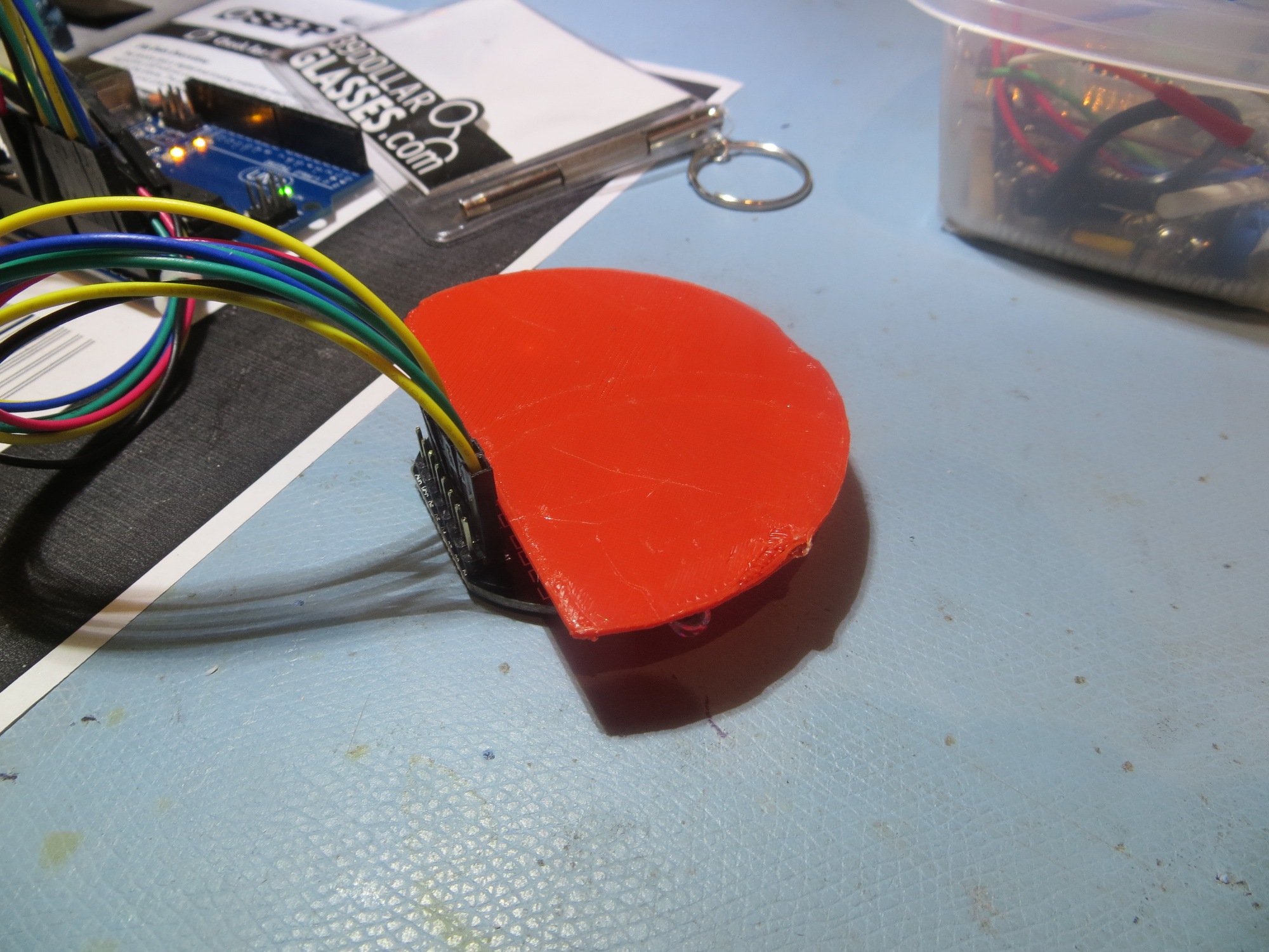
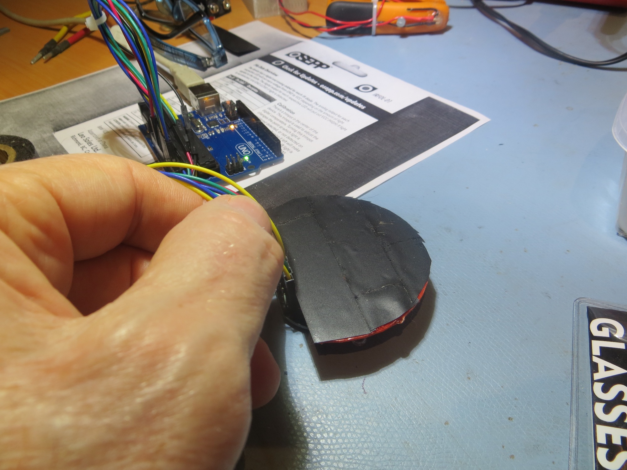
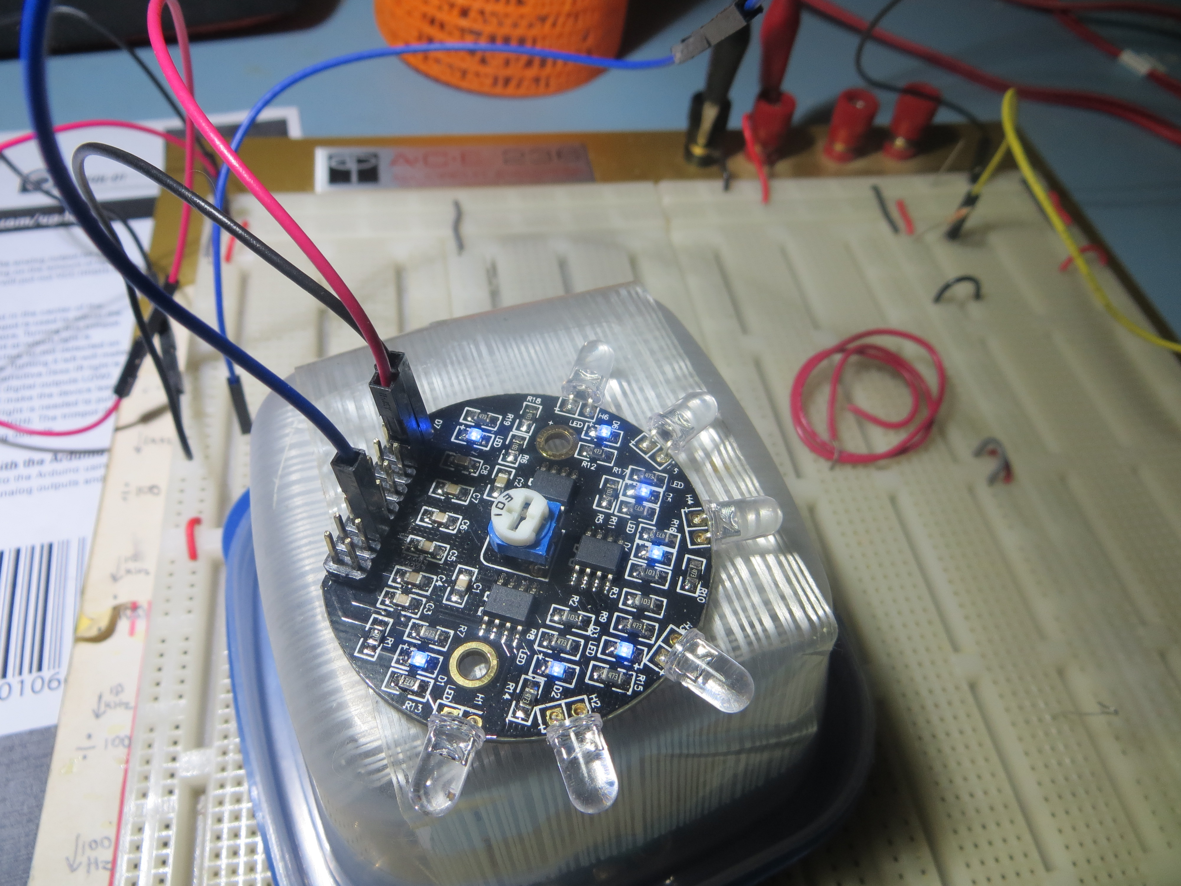
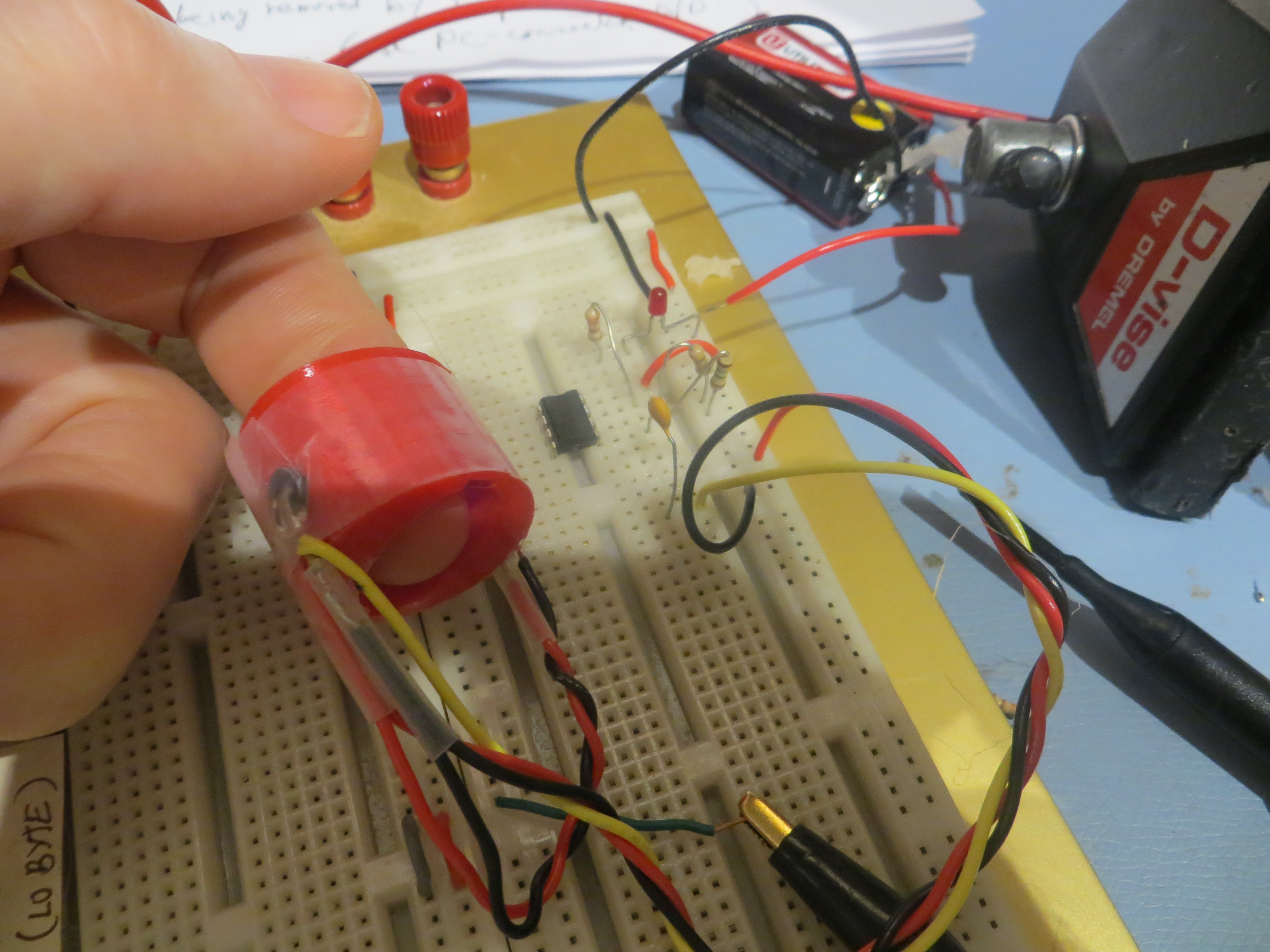
So, Prof Anderson was gracious enough to bring a spare OXO clip to our next Outreach session, and since then I have had the opportunity to test this clip with my new circuit, as shown in the following photo.
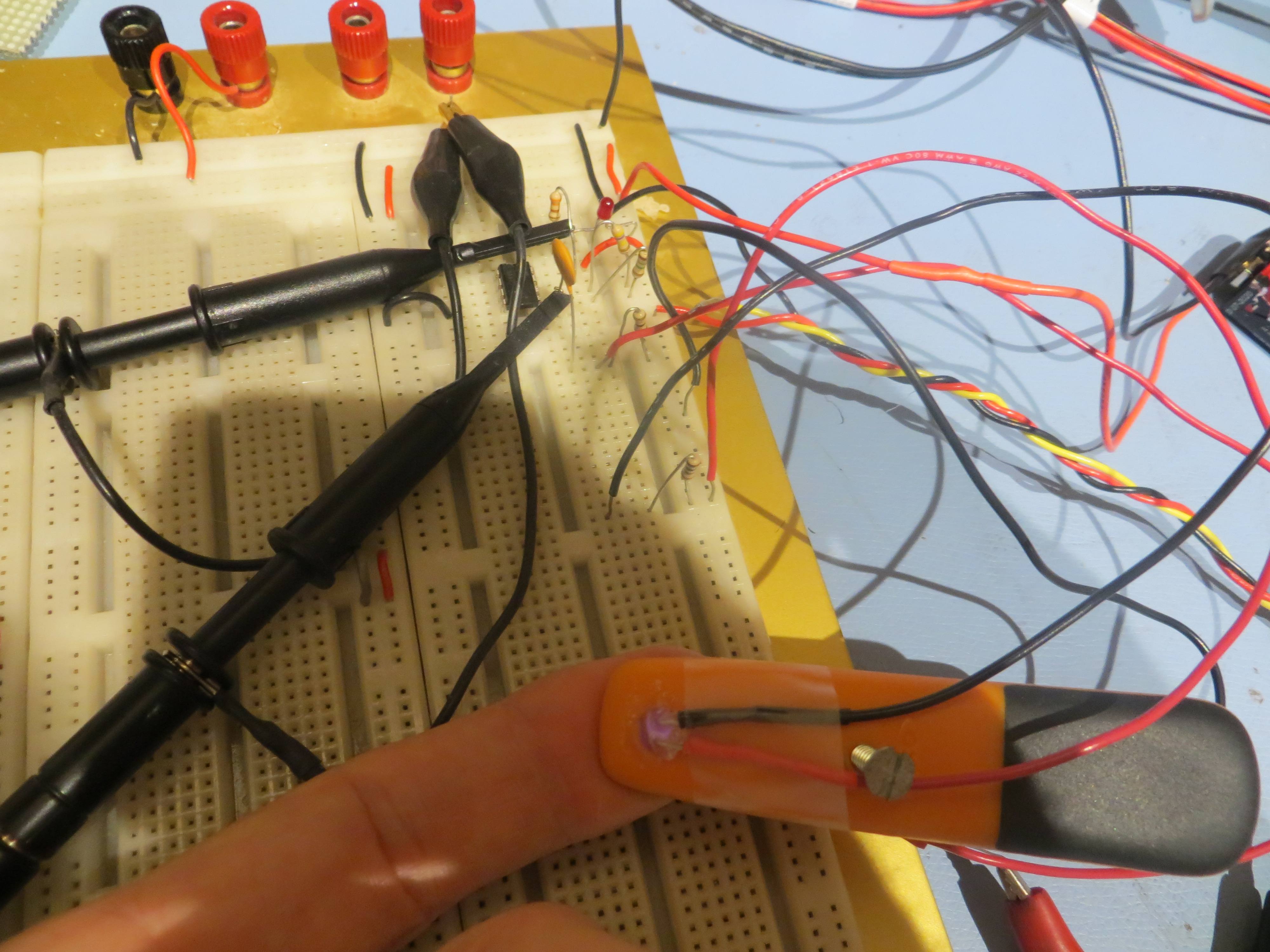
OXO ‘Soft-Clip’ finger clip with new circuit in background
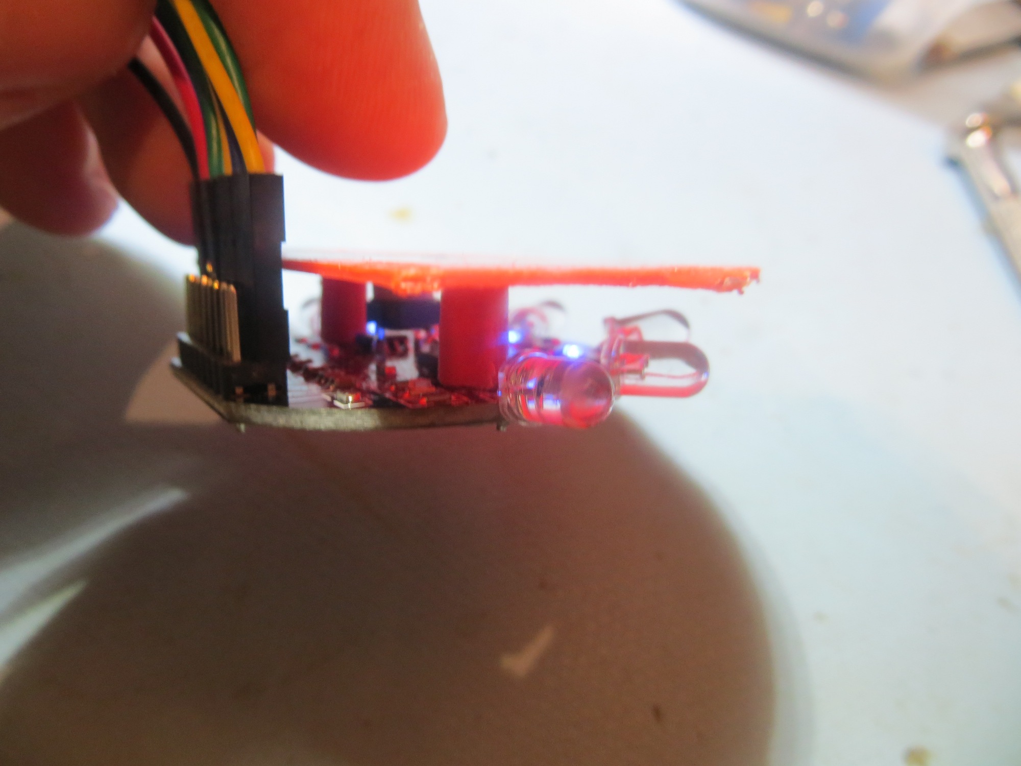
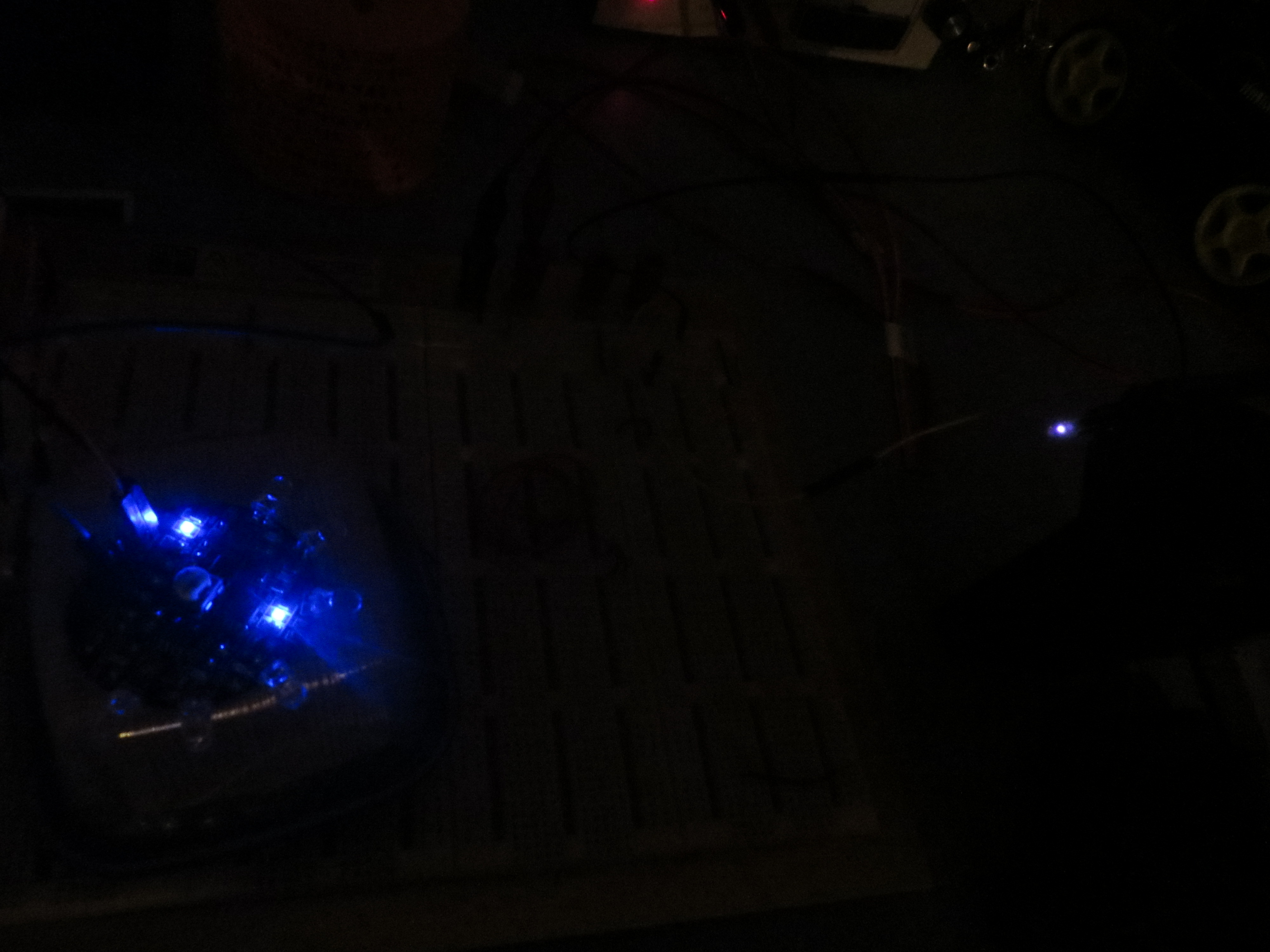
After fiddling with the tension screw a bit, I got the Soft-Clip tension set properly for my finger, and lo-and-behold, the pulse detector circuit worked out quite nicely, as shown in the following short video clip (as you watch the clip, note that the IR beam from the IR LED is visible as a blue-white glow).
At this time I also made one other minor change. In the original OSU circuit, the DC blocking capacitor (C2 in the schematic) was a 0.1uF, but in my circuit this value was changed to 0.01uF, because that’s all I had on hand. In the meantime, however, I got some 0.1uF’s from Mouser, and so my final circuit as shown above incorporates a 0.1uF vice the original 0.01.
The next step in this project is to transfer the detector circuit from plugboard to a more permanent version on perfboard. This will allow me to demonstrate the new circuit to Prof Anderson and the rest of the OSU STEM Outreach team, to lend credence to the idea of modifying this project’s documentation to eliminate the now-unneeded second supply. Stay tuned!
Posted 10/24/2016
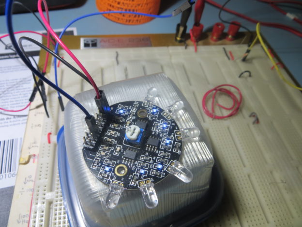
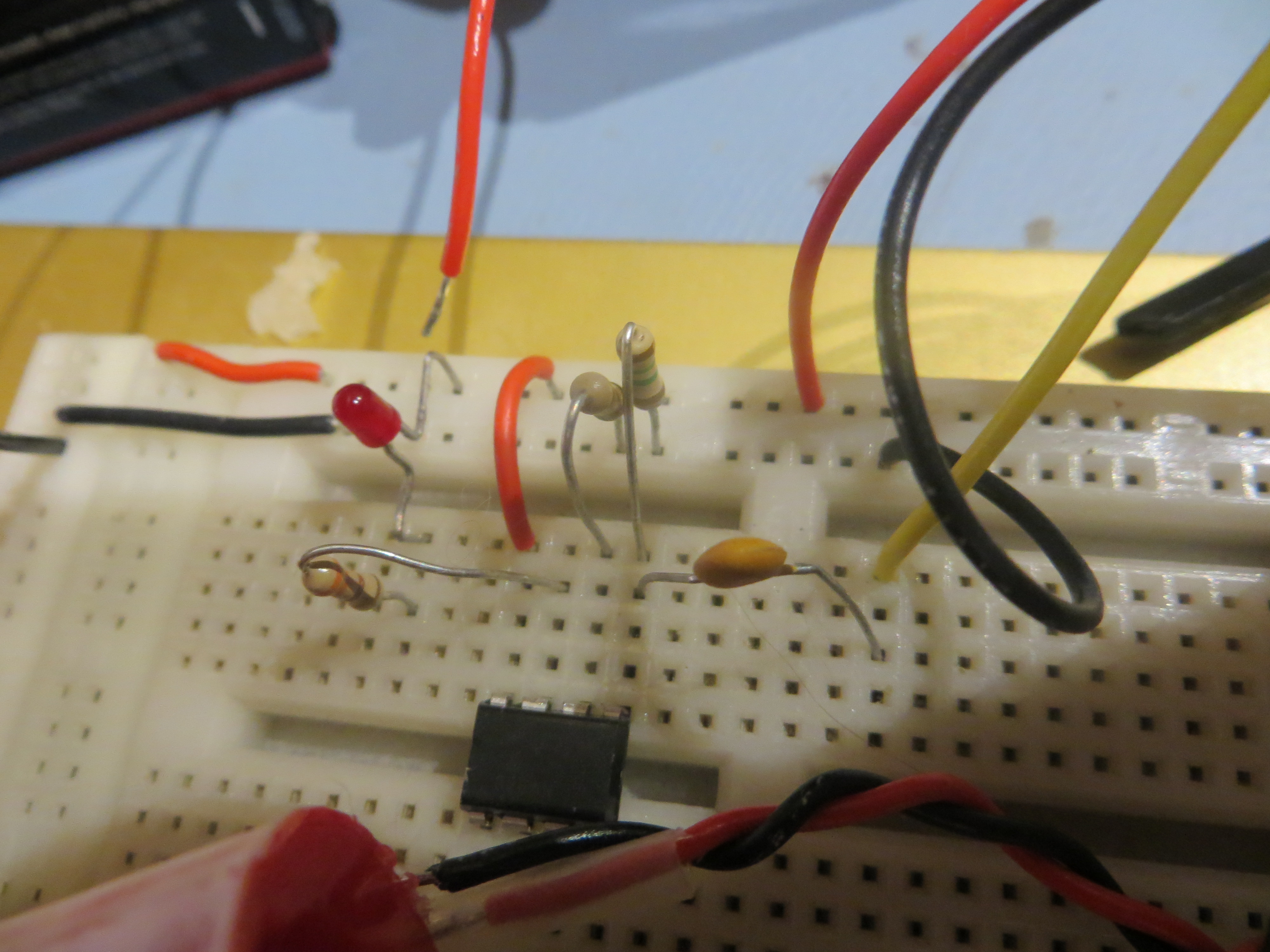
So, tonight I had the time to finish transferring the pulse detector circuit from my old trusty plugboard to a more permanent medium – i.e. perfboard. The idea here is to provide the OSU STEM Outreach team with a working pulse detector circuit running from a single 9V battery, as a working example of my recommended modifications to the circuit being used presently. The image below shows the perfboard arrangement, and there is also a short video clip of the new pulse detector circuit in action.
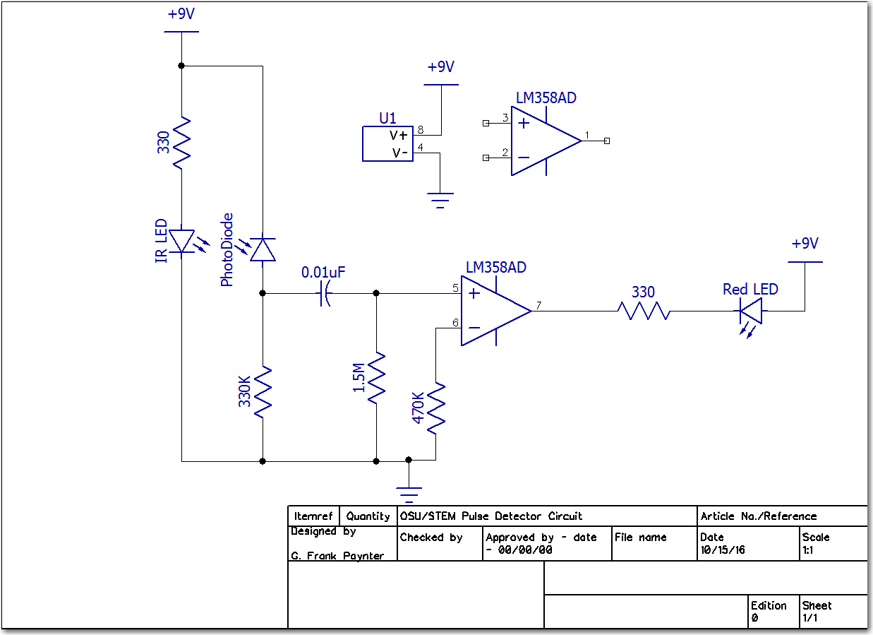
The astute observer might notice there are only three wires going from the OXO ‘Soft-Clip’ assembly to the pulse detector circuit. While I was wiring up the perfboard version, I realized I could eliminate one wire by simply moving the 100-Ohm IR LED current-limiting resistor from the anode (positive) side of the diode to the cathode (negative) end. This allowed me to connect the IR LED anode to the PhotoDiode cathode, and both to the +9V lead. Implementing this change for all of the current stock of OXO clips may be more than the OSU STEM Outreach crew wants to take on, but I thought I would mention it ;-). The finished schematic (with the transposed 100-Ohm resistor) is shown below
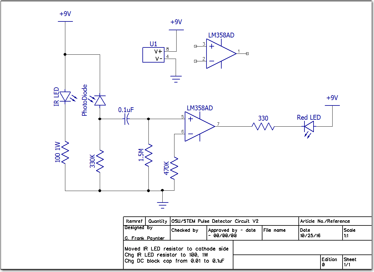
Final pulse detector schematic. Note change to IR LED current limit resistor, and DC blocking capacitor
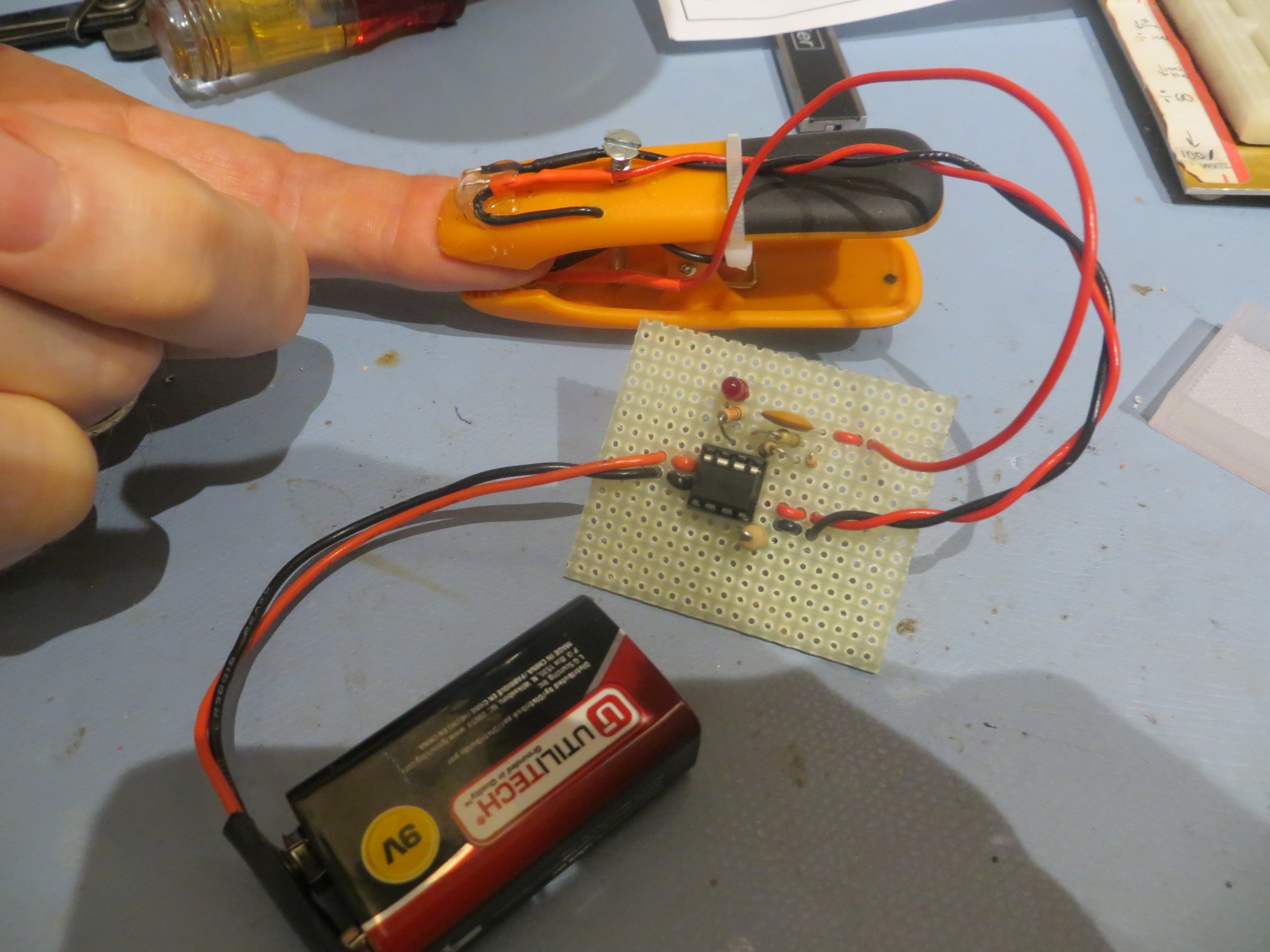
Perfboard version of the single-supply pulse detector circuit
The next (and hopefully final) step in all this is to 3D print a small box for the perfboard circuit. Because I can’t help myself, I have decided to try printing a transparent box – not a trivial undertaking for 3D printing. Stay tuned!
Posted 10/25/2016
As mentioned above, 3D printing a transparent box is a non-trivial undertaking, at least with the current hobbyist FDM (Fused Deposition Modeling) materials and techniques. After a number of iterations, the best I could do without a lot of post-processing was a semi-transparent (but still pretty neat) container for the perfboard version of the ‘new-and-improved’ OSU Pulse Detector circuit.
As I have noted previously, the current 3D printing technology makes it easier, faster, and cheaper to go through a number of test cases (literally in this ‘case’!) on the way to a final product, rather than trying to design a final product all in one crack. Each test takes about 15-30 minutes and just a few cents’ worth of material, and quite often the iterative process illuminates a design problem or opportunity that wasn’t obvious (or even considered) at the start. In this case, it became apparent after about the 4th iteration that the perfboard should be mounted to the ‘lid’ via printed-on standoffs rather than to the ‘bottom’.
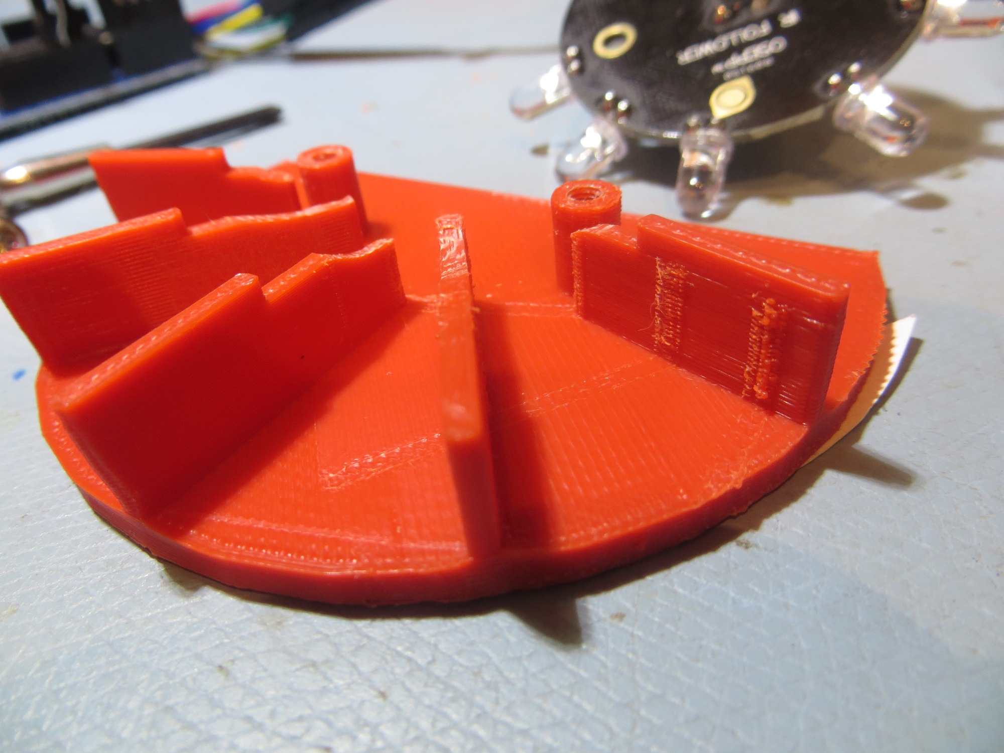
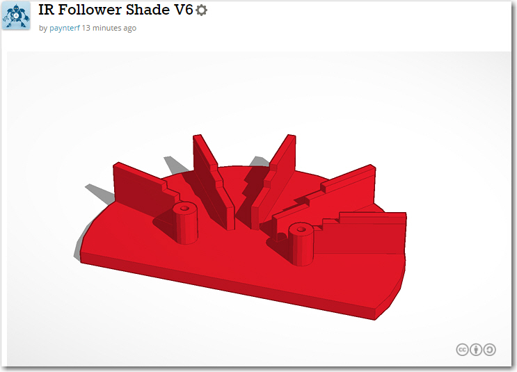
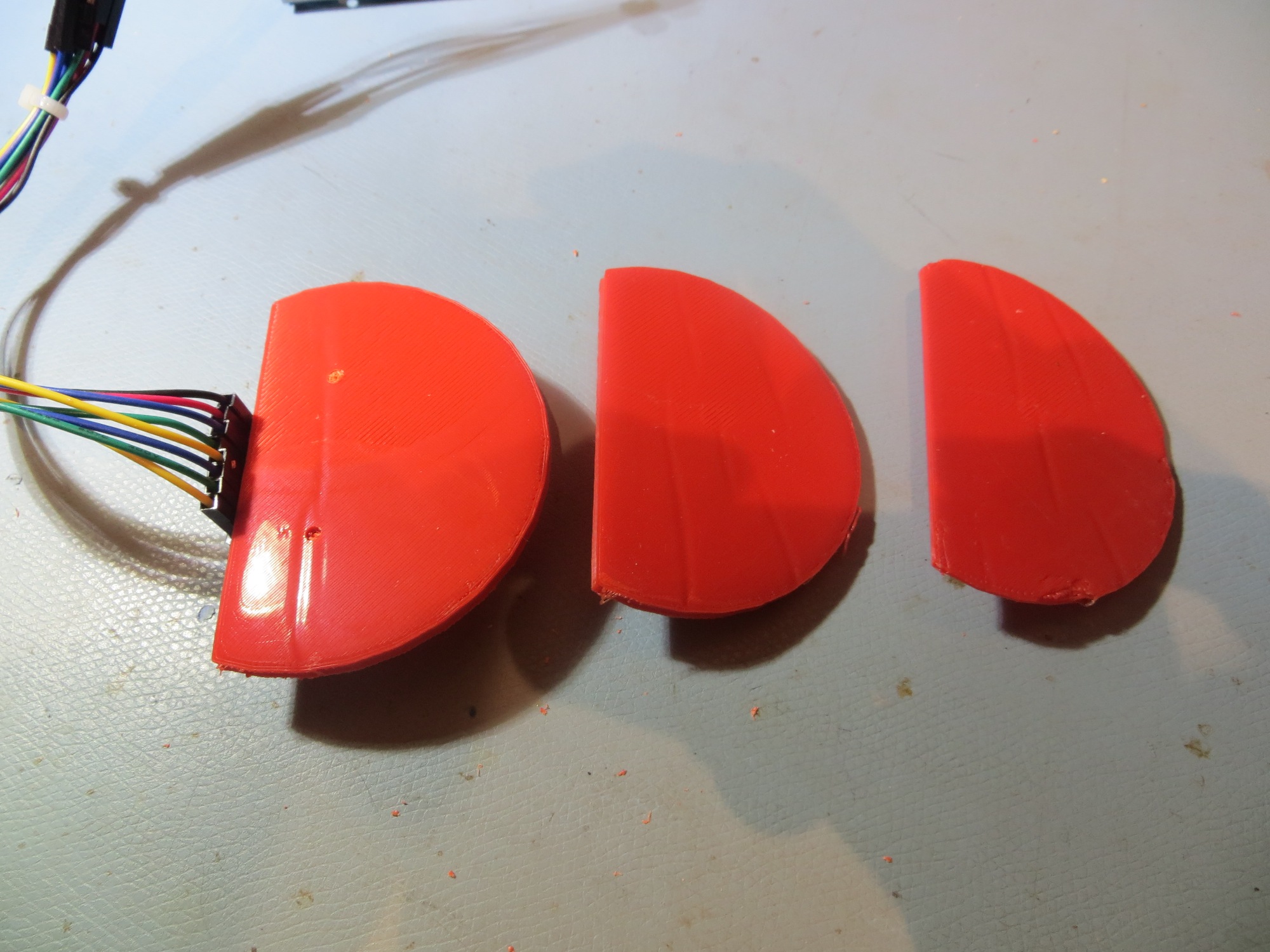
The TinkerCad model for the box and the lid is shown below, as well as the finished product and some of the precursor test boxes. And, as usual, a short video of the final product.
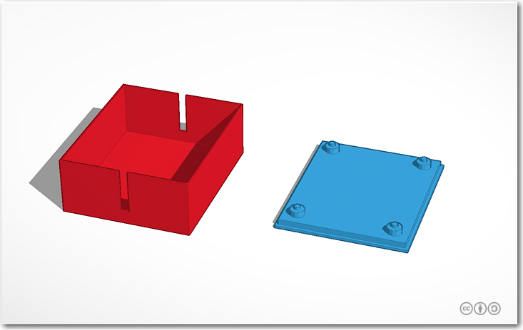
Pulse Detector Box and lid. Note printed-on standoffs
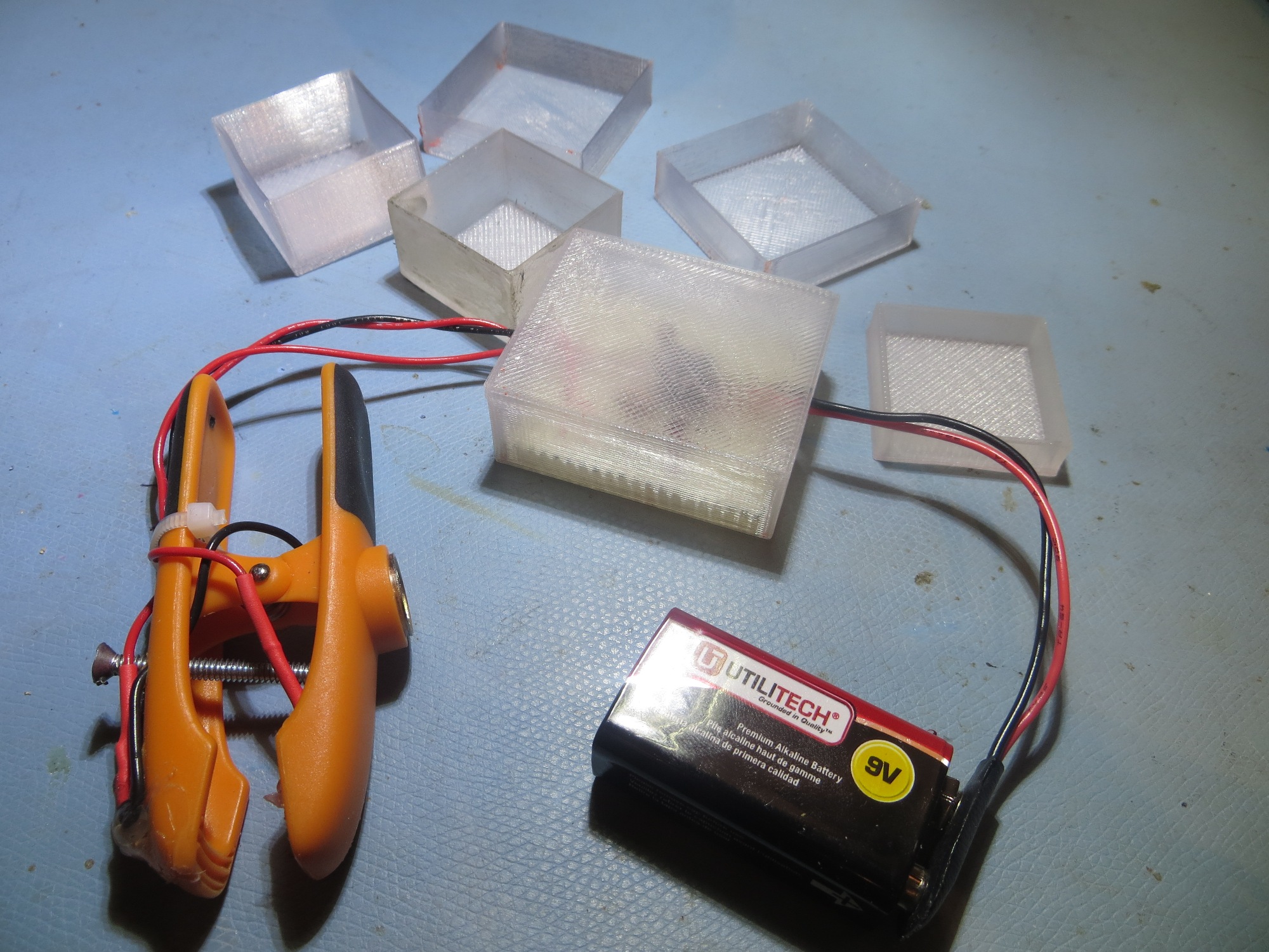
OSU Pulse Detector Box and precursors
Frank