Monthly Archives: September 2016

Wall-E2 Charging Station, Part I

Posted 09/28/16

Ever since I started the Wall-E wall-following project, my goal has been to give Wall-E the ability to periodically recharge his battery without human intervention.  Then Wall-E would be free to roam the house indefinitely, striking fear into the hearts of humans and cats alike! ;-).

The concept for the Wall-E charging station has gone through  a lot of iterations, at least during my drifting-off-to-sleep conceptual design sessions.  Eventually I settled on a concept where Wall-E would be captured by some sort of lead-in railing which would force it onto a raised platform containing the charging power supply.   The platform would contain a set of spring-loaded contacts that would mate with contacts on the underside of Wall-E for charging power and for charging state control.

To start the process, I ran some tests to determine the basic requirements for the lead-in structure.  To support these tests, I modified Wall-E’s code to emulate its tracking behavior, but with an on-off push-button so I could run multiple tests without Wall-E running away.

As the following video snippet shows, my first idea of a low-sided lead-in wall was defeated in short order by Wall-E’s motor torque and soft, knobby wheels.
Speaker Amplifier Project, Part V

Posted 10 September 2016

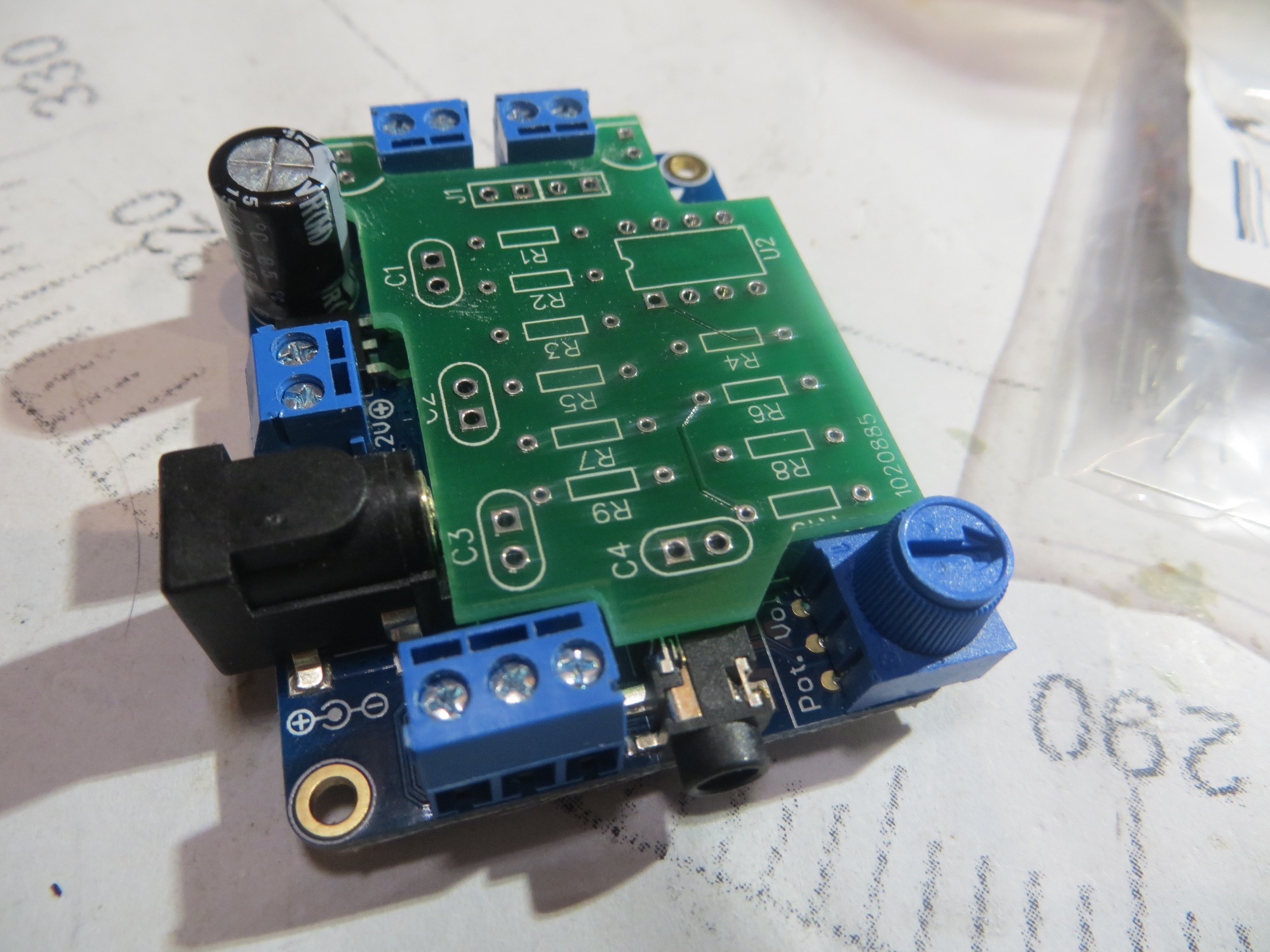
Since my last post on this subject, I have actually gone through two revs of the PCB. The first set was fine electrically (and great quality AFAICT, but I didn’t get the physical border just right, and  I couldn’t file it down enough to fit without breaking a PCB run.  So, I went back to DipTrace, redid the board outline (which also involved some rejiggering of component placement and a bit of manual net editing) and sent off another order to Bay Area Circuits.  After returning from  a week at a duplicate bridge tournament in Atlanta  with my wife, the new rev boards were waiting for me – cool!  The image below shows the new board as installed on the Adafruit 20W amplifier board.

Rev2 PCB installed on Adafruit amplifier

Rev2 PCB installed on Adafruit amplifier

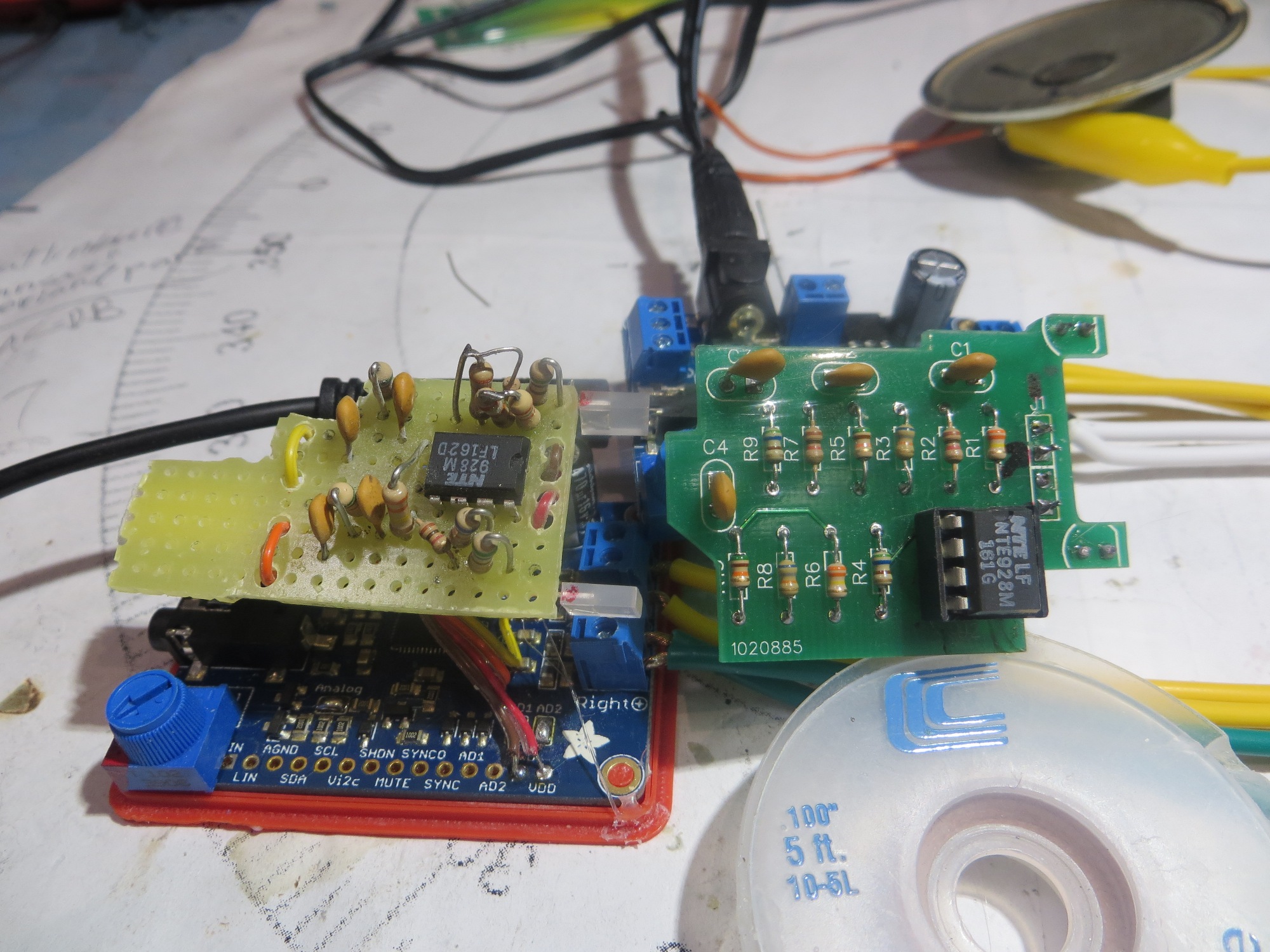
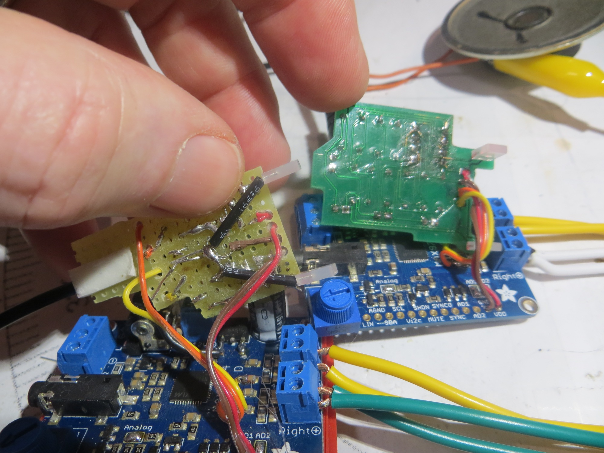
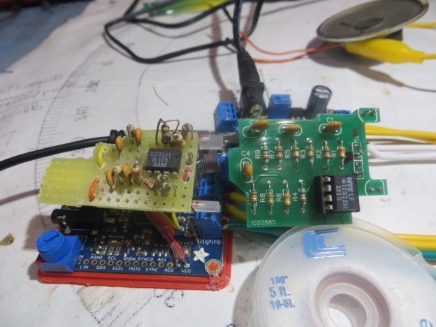
After ensuring that the PCB fit was OK, I populated it, checked all the net connections and resistor values and gave it the old smoke test – and of course it failed – ugh!  I quickly found that the problem was that common-mode range of the the MC748 dual op-amp I was using for the second system doesn’t include ground – oops!  A quick trip to the local Microcenter and the purchase of a wildly overpriced NTE928 dual op-amp solved that problem, but because I was I had soldered the op-amp package directly onto the board (I was  sure this was all going to work, after all), I was now faced with a messy removal and cleanup job.  After getting the old op-amp off and the PCB cleaned up, I installed the new one  (this time, suitably chastised, I installed a socket, and  then installed the op-amp).  The following image shows the finished PCB connected to the amp board, next to the hand-wired original.

Completed PCB connected to Adafruit amplifier

Completed PCB connected to Adafruit amplifier

Bottom of PCB and hand-wired original (note messy area around op-amp)

Bottom of PCB and hand-wired original (note messy area around op-amp)

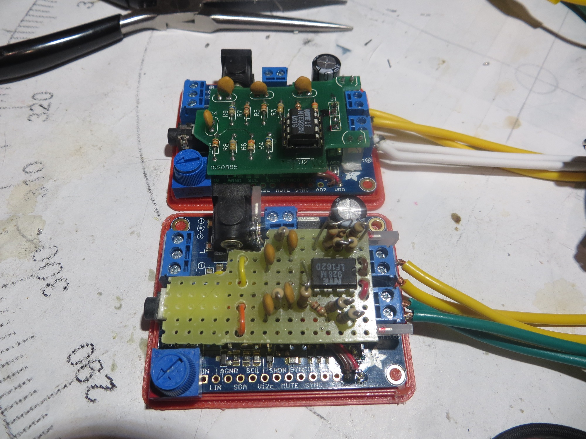
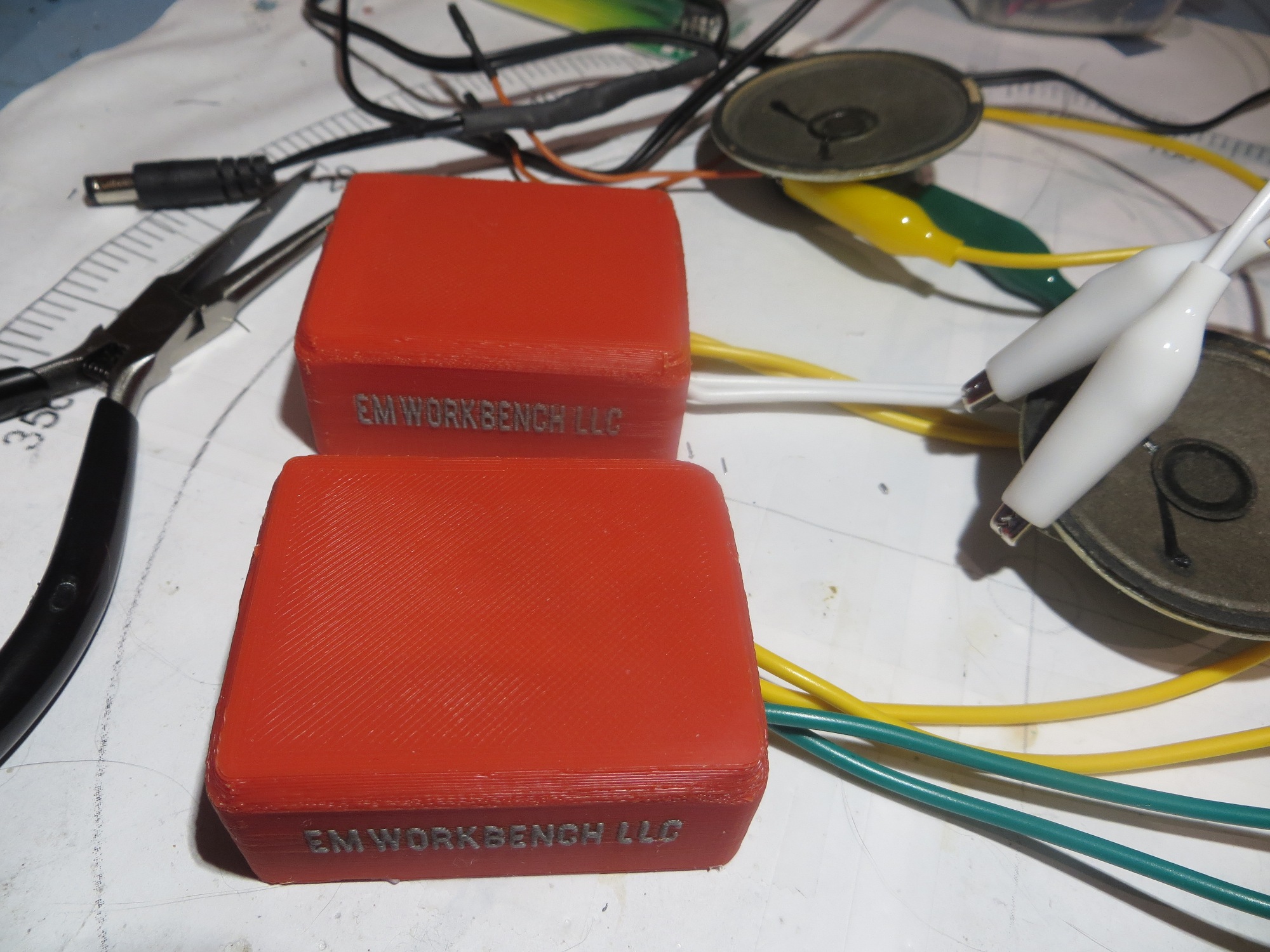
The last thing to do was to get the PCB actually mounted onto the amplifier board, and the assembly into its custom-printed housing, as shown in the following images.

hand-wired and Rev2 PCB mounted to the Adafruit amp boards

hand-wired and Rev2 PCB mounted to the Adafruit amp boards

hand-wired and rev2 PCB mounted in custom-printed enclosures.

hand-wired and rev2 PCB mounted in custom-printed enclosures.

Now all I need is a ‘speaker’ presentation so I can find out if all this work was really worthwhile (actually, I’ve already had a great time with this project, so having it actually work for the students will just be icing on the cake!)