Posted July 25, 2016
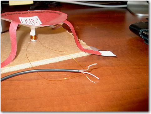
Lately I have become involved in the Engineering Outreach program here at The Ohio State University, as a volunteer helper at ‘hands-on’ engineering project presentations to grade-school and middle-school students in the Columbus, Ohio area. A week or so ago I helped out in a session where the students (middle-schoolers at a science day-camp) got to fabricate and test an audio speaker from a paper template, some magnet wire, and a couple of small permanent magnets, and I was struck by the difficulty the kids were having in actually hearing anything coming out of their freshly-fabricated speakers when they connected them to the output of their phones and/or iPads. I could understand if I couldn’t hear anything – I’m an old power pilot and my ears are shot from thousands of hours of piston engine noise – but the kids with their brand-new ears couldn’t hear anything either! There was an audio amplifier available for the kids to use, but it wasn’t much help either – there wasn’t any indication that the amp was actually doing anything, so it could have died long ago and nobody would ever know – bummer. Anyway, I came away from that project with the distinct impression that this particular project wasn’t doing much for the kids, and maybe I could do something to help. So, before I left the room, I made a point of ‘borrowing’ all the parts required to fabricate my own paper speaker – the paper template, magnet wire, and permanent magnets along with the other small bits and pieces.
My first line of inquiry in my own home lab was to determine what the best fabrication technique was for the speaker itself. My thinking was that since this project has been around forever in one guise or another, it sorta had to be successful in some sense, or it would have died out long ago. Therefore, I reasoned that a more careful approach to the actual fabrication might yield better results. After doing some inet research, I realized that one of the critical aspects of paper speaker construction is to make sure the speaker coil assembly (a section of plastic straw hot-glued to the speaker cone with the magnet wire wound around it’s lower end) was free to move vertically – i.e. it wasn’t forced down against the baseplate by the tension of the speaker legs. In other words, the speaker legs had to be arranged such that the speaker coil assembly floated 2-3 mm above the base. After playing with this a while, I realized that the proper technique was to arrange the speaker legs so as to properly suspend the coil assembly first, and then place the permanent magnet ‘dot’ under the coil assembly second, rather than the other way around. Assembly in this sequence tends to minimize lateral friction of the coil assembly straw section against the side of the permanent magnets, hopefully resulting in higher mechanical/audio transfer efficiency.
After constructing the speaker as carefully as possible, I hooked it up to my laptop audio output, and voila! – no audio :-(. Even with the audio output at max volume (which, when directed to my laptop’s internal speakers is enough to vibrate my workbench), it was almost impossible to hear anything from the speaker. Even with careful construction with no time constraints, and a top-end audio source, getting the speaker to work was a very marginal deal.
After thinking about this for a while, I decided that I was maybe working the wrong end of the system. What I needed to do was to implement an audio amplifier that would provide sufficient output power so that even a marginally constructed speaker would work properly; the only real limitation on power that I could see would be the current limit imposed by the magnet wire itself – as long as I didn’t physically melt the wire, I should be OK! ;-).
My first try at an amplifier was based around a power MOSFET I had lying around, as shown in the following photo. 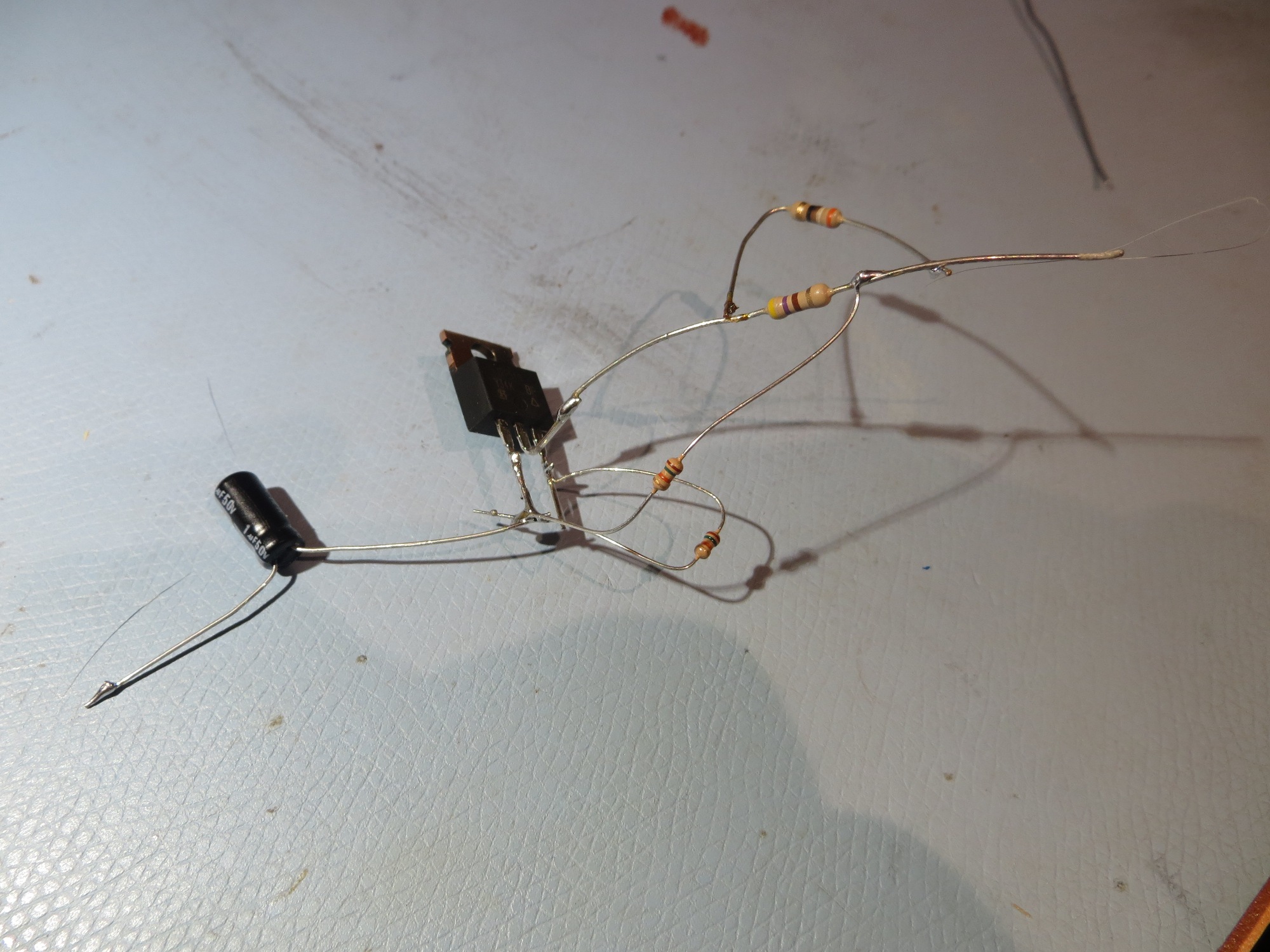
This worked ,but only up until the point at which the drain resistor started smoking! That’s the problem with a linear amplifier driving a speaker – LOTS of power being dissipated.
So, back to the drawing board, with more inet research. This time, I came across the very nice Adafruit Class-D speaker amplifier shown below. The kit has everything needed to build a complete speaker amp, as shown in the second image below. The amplifier runs Class-D, so it is very efficient, and it depends on the speaker coil inductance to reject the high-frequency switching signal, leaving only the audio.
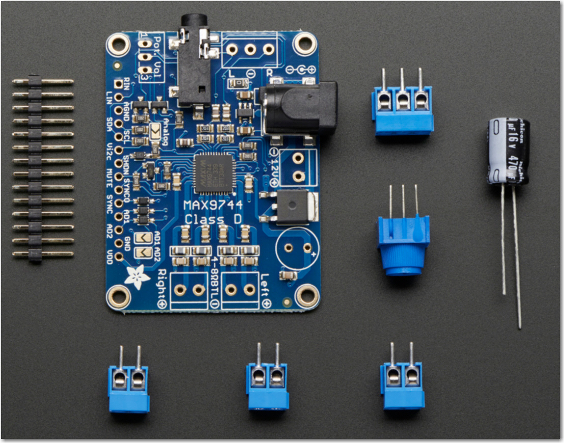
Adafruit 20W Class-D speaker amplifier, based on the MAX9744 amplifier chip
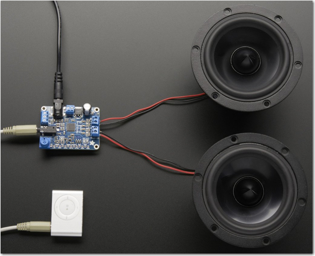
Adafruit 20W Class-D speaker amplifier application
The folks at Adafruit were even thoughtful enough to provide the STL file for a 3D-printable enclosure for the amp, as shown below:
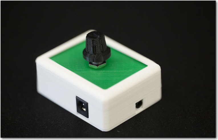
3D-printable enclosure for the 20W Class-D amp
And, since I am the proud owner of not just one, but two 3D printers (a Printrbot Simple Metal, and a PowerSpec 3D Pro/aka Flashforge Creator X), the existence of a ready-made design for the enclosure saved some time.
After receiving my amps from Adafruit, and after the requisite amount of fumbling around, I managed to get the amp running and connected to a couple of old speakers. When I connected up my laptop’s audio output I was quite pleased that, even at the default 6dB gain setting, the amp easily drove the speakers to the point where I had to reduce the audio input volume to avoid complaints from the wife in the next room.
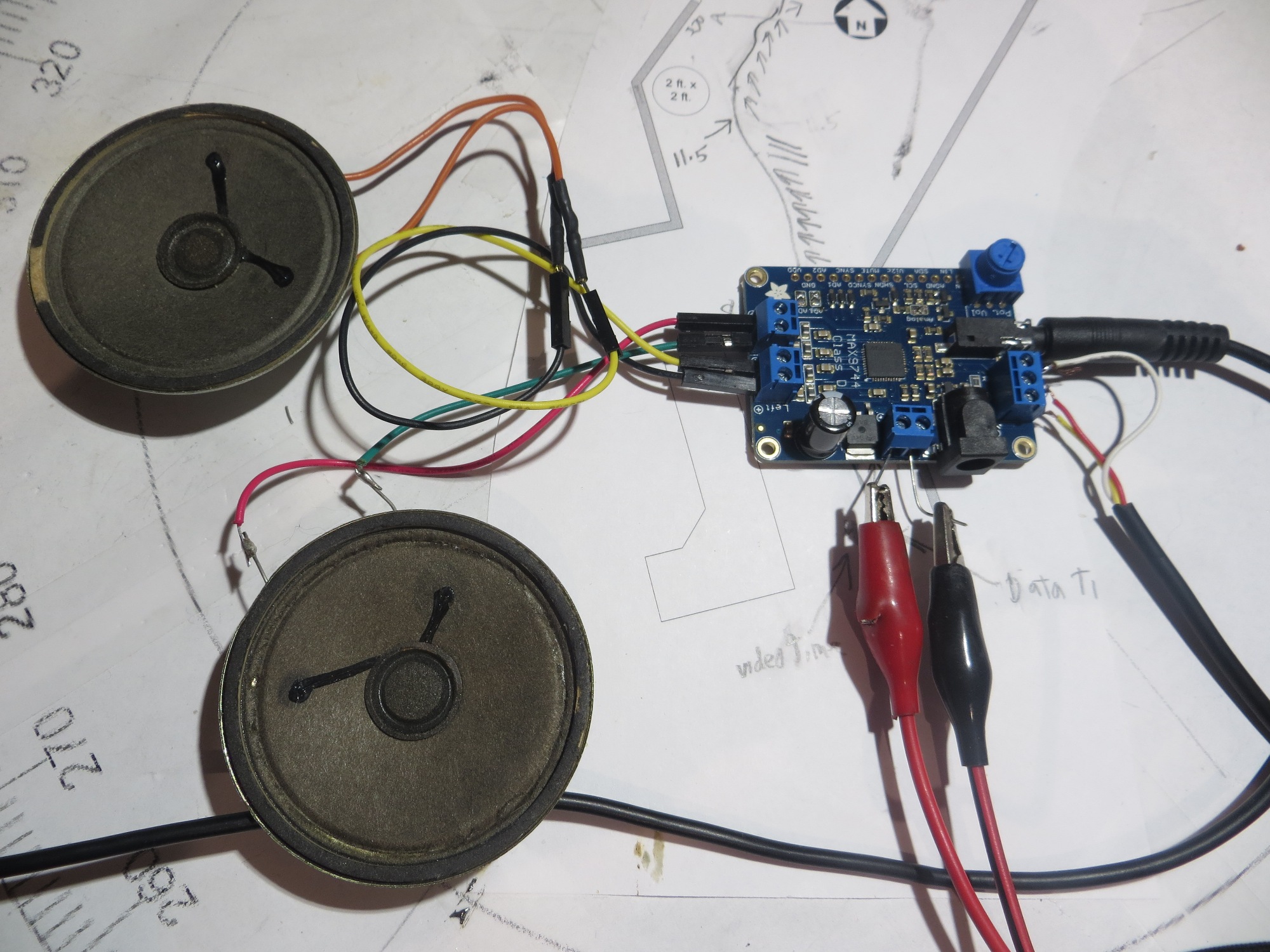
Adafruit amp test setup
At this point, it was clear that the Adafruit amp should be an excellent solution to the paper-speaker driver problem, but I wasn’t quite done yet. There were still several remaining issues:
- The amplifier used in the previous sessions had no ‘power ON’ indication, so there was no way to tell if the thing was actually operating or not. The Adafruit amp, as delivered doesn’t have one either, so this had to be corrected somehow.
- The previous amplifier had no ‘audio activity’ indication, so even if you somehow knew that it was indeed getting power and working, there wasn’t any way to tell if there was any audio output without attaching a speaker; and if there was no sound, there was no way to tell if the problem was the speaker or the amp.
- The original enclosure design by Adafruit didn’t actually fit – the slots for the power and audio-in jacks weren’t high enough (later design change?). In addition, there were no provisions for either the ‘power ON’ or ‘audio activity’ indicators. Fortunately I not only have 3D printers, but an account on TinkerCad so the design could be adjusted.
- Since I still haven’t actually connected the amp to my paper speaker, I don’t really know yet if the default 6dB gain setting is sufficient to drive the speaker; I may still have to change to the analog gain setup and use a higher gain setting (fortunately, Adafruit thoughtfully provided a 1K potentiometer and a set of jumper pads to achieve this, if necessary).
Power-ON Indication:
The power-ON indication issue was fairly easy to address – all I had to do was add an LED-resistor combination across the external power input lines. The only problem with this solution was finding a way for the LED to be visible outside the enclosure – and the solution was to modify the enclosure design to expose the external power screw terminals (they were hidden in the original design), and in the process leave a bit of space open between the power input jack and the screw terminal, a space just wide enough for a small, rectangular LED as shown below.
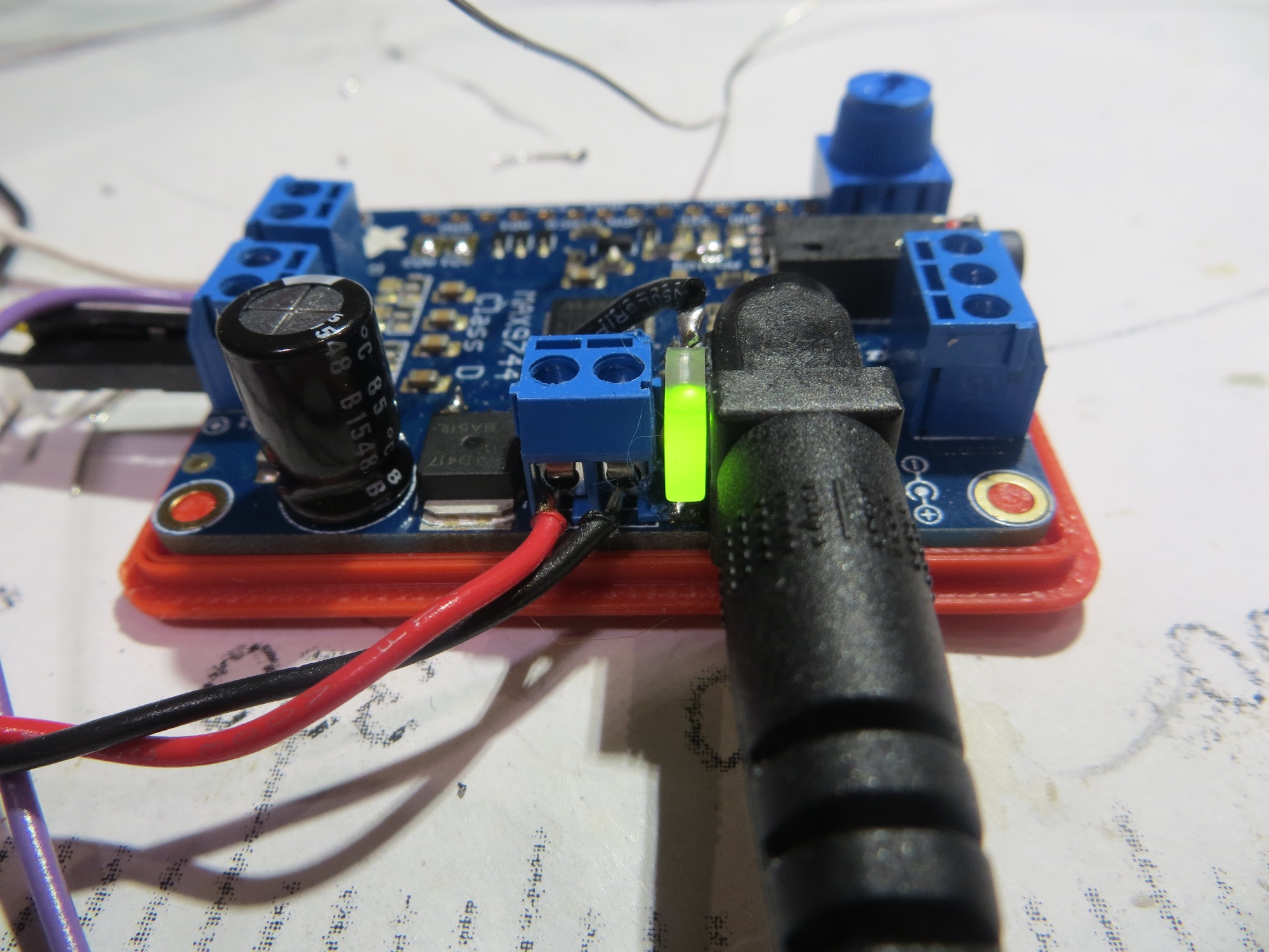
Power ON indicator LED installed between power input jack and external power screw terminals
Audio Activity Indicator:
The Adafruit amplifier is Class-D – i.e. the output is a pulse-width-modulated (PWM) signal, as shown below:
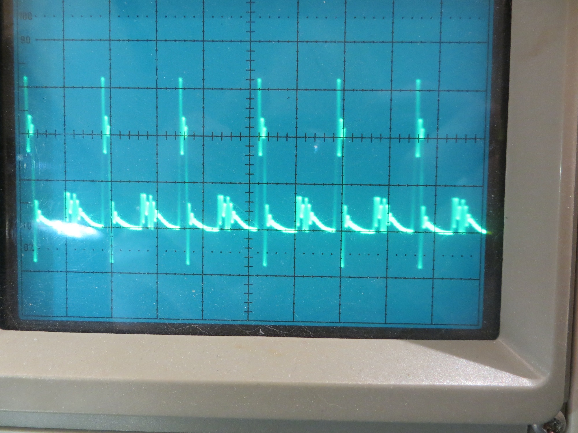
Amplifier output with audio input signal present
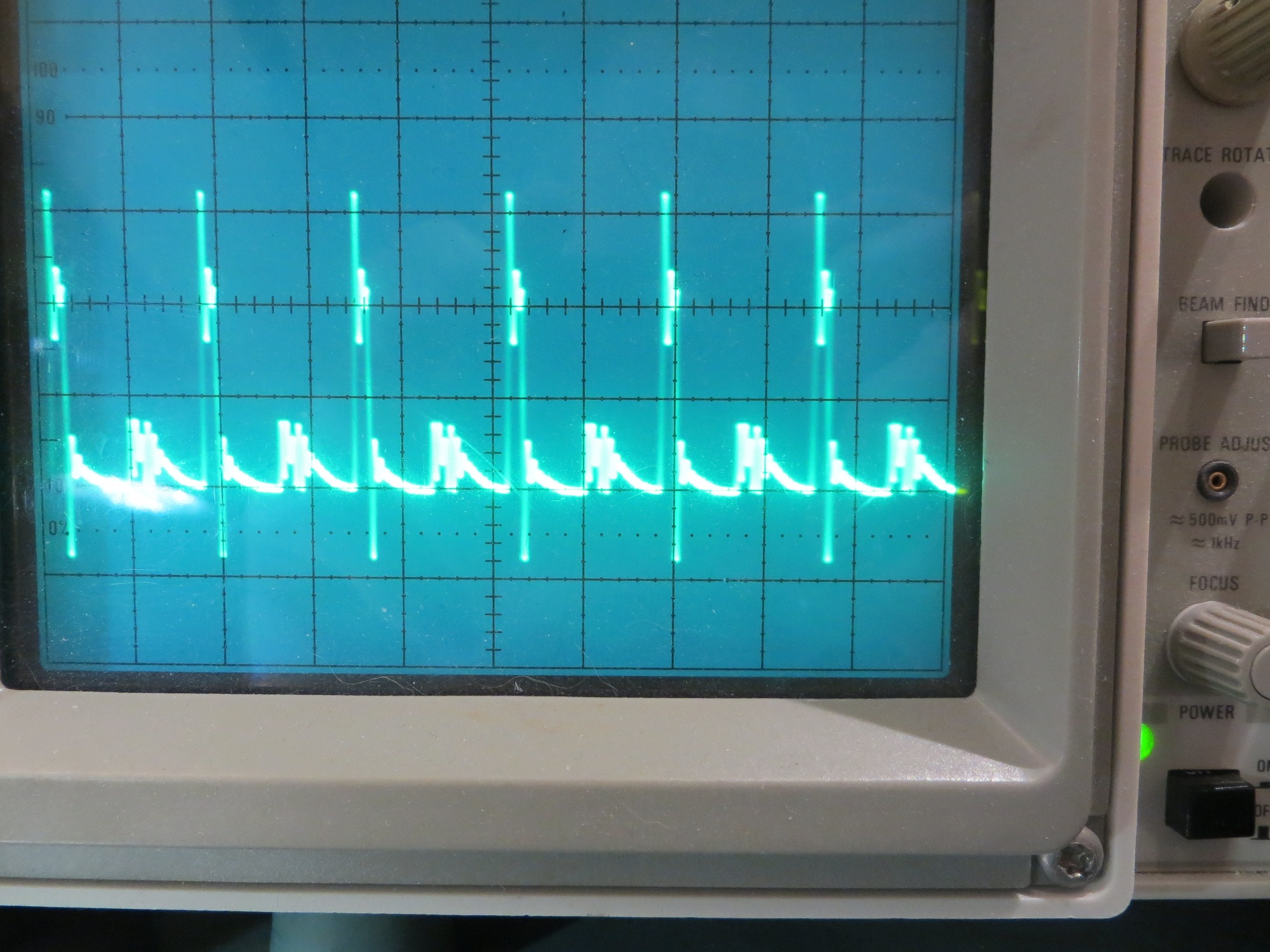
Amplifier output with no audio input signal present
As can (or more accurately, cannot) be seen from the above photos, there is no appreciable difference between the ‘audio’ and ‘no audio’ waveforms. The class D amplifier technique depends on the low-pass nature of the speaker coil to suppress the high-frequency switched waveform terms, leaving only the audio term. Unfortunately, this means there really isn’t anything there to directly drive an audio activity indicator – the typical LED is plenty fast enough to follow the high-frequency PWM waveform, thereby masking the audio signal. One possible technique would be to sample the speaker coil current (which pretty much by definition doesn’t contain the high-frequency switching terms), but this requires that a working speaker be attached. This won’t work, because the whole idea of an audio activity indicator is to confirm that an audio input is present and has been amplified sufficiently to adequately drive a speaker before one is connected. So, I decided to try a simple RC low-pass filter, followed by a basic audio amplifier to drive the activity LED. The circuit for one channel is shown below.
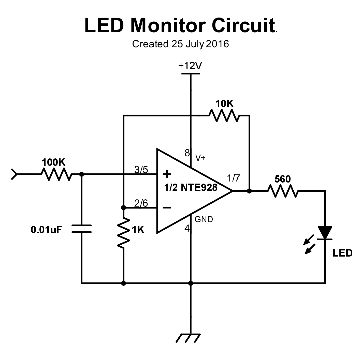
LED monitor circuit for one channel. Pin numbers are Channel1/Channel2
Here is a short video showing the LED monitor circuit in action
So, at this point I have a working speaker amplifier, a power-ON indicator, and at least the prototype of an audio activity monitoring circuit. Next up – finish the LED monitor circuit, finish the enclosure design and fabrication, and assemble everything for delivery.
Pingback: OSU/STEM Outreach Speaker Amplifier Project, Part II - Paynter's Palace
Pingback: Giving Wall-E2 A Sense of Direction, Part IX - Paynter's Palace