Posted 27 July 2016
In my last post on this subject, I had gotten to the point where I had a single-channel LED monitor circuit working, although it was still a bit unkempt, to say the least. In this post I describe the effort to get both channels working and to neaten everything up prior to installing the circuit into the speaker amplifier enclosure.
First off, I ‘improved’ the LED monitor circuit a bit, based on the results from testing the one-channel version. I discovered there was a DC term riding on the class-D input signal, and this was getting amplified through the LED monitor circuit and swamping the audio output at the LED. So I added a 0.01uF DC blocking cap on the input line. Unfortunately, this caused another problem, in that now the RC circuit cap had no discharge path so it almost immediately charged up and again swamped the audio signal. One more addition – a 330K Ohm resistor across the low-pass cap to allow it to discharge. Then, I adjusted the DC gain of the amp to provide a good LED response to the audio. I wanted the LED’s to come alive just about the time that a well-fabricated speaker produced clearly audible output. The idea here is that a helper can tell immediately from the LEDs whether or not there is sufficient output power present to produce an audible response, and therefore if no response is detected, there is a problem with the speaker or the wiring from the amp to the speaker – but not upstream of that point. After some fiddling around, I settled on a gain of about 70 for the LED monitor. With that setup, and with the 20W amp gain set appropriately, I could easily drive the OSU paper speaker from my laptop, with the laptop’s audio output slider at about 50%. The ‘New Improved’ LED monitor circuit is shown below:
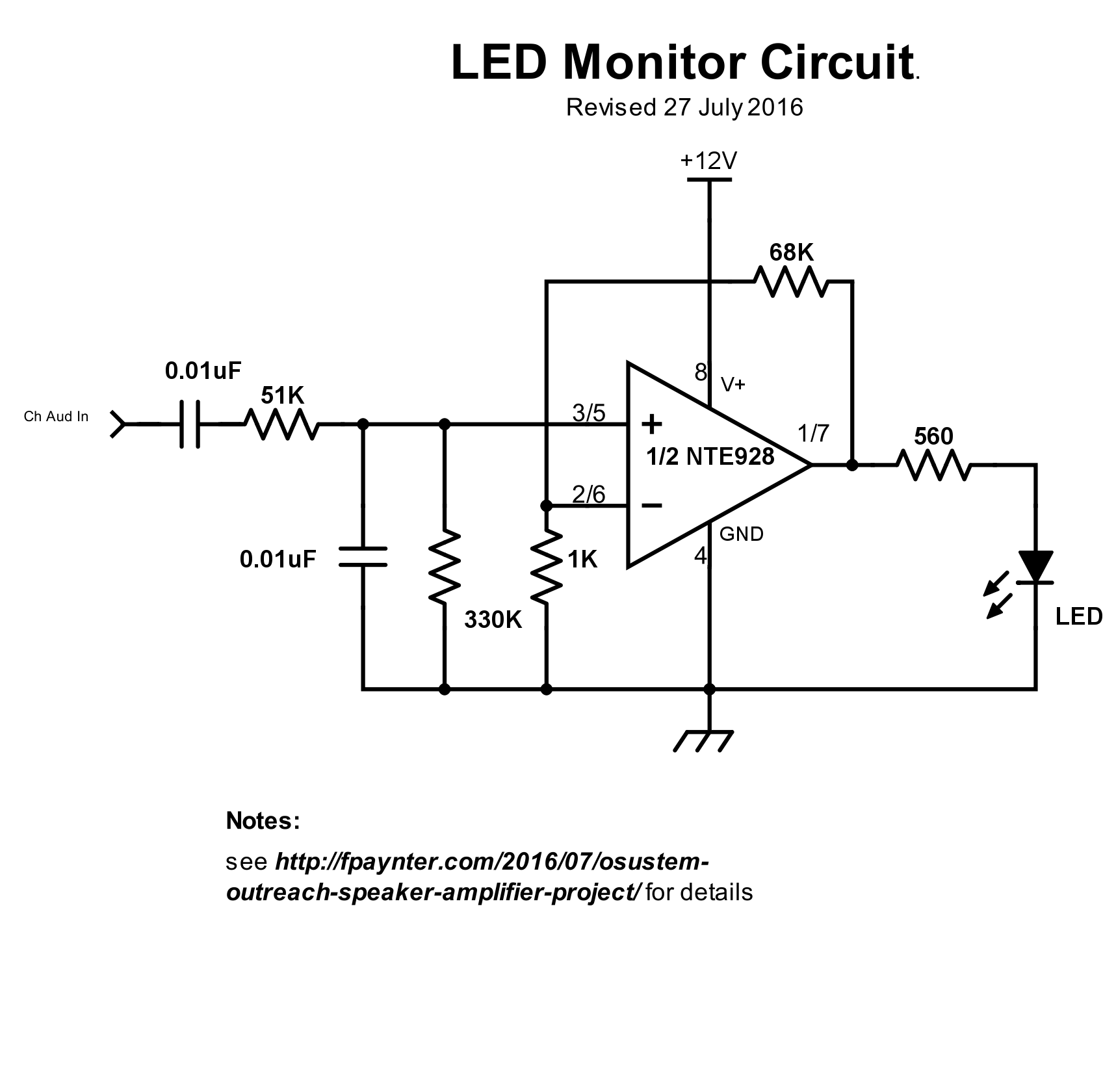
Revised LED monitor schematic – one of two channels shown.
The audio input to the monitor circuit is the rail-to-rail high-frequency (about 300KHz) audio-modulated PWM signal, as shown below
Amplifier output with audio input signal present
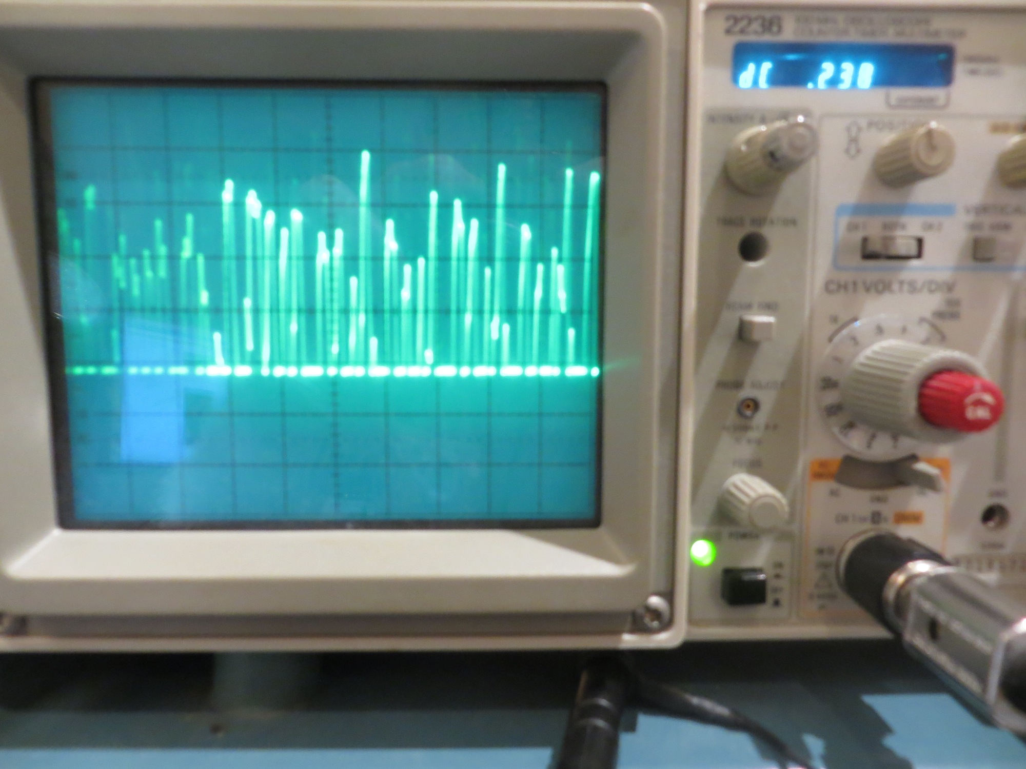
After the RC filter, only the audio signal is present, as shown in the following photo
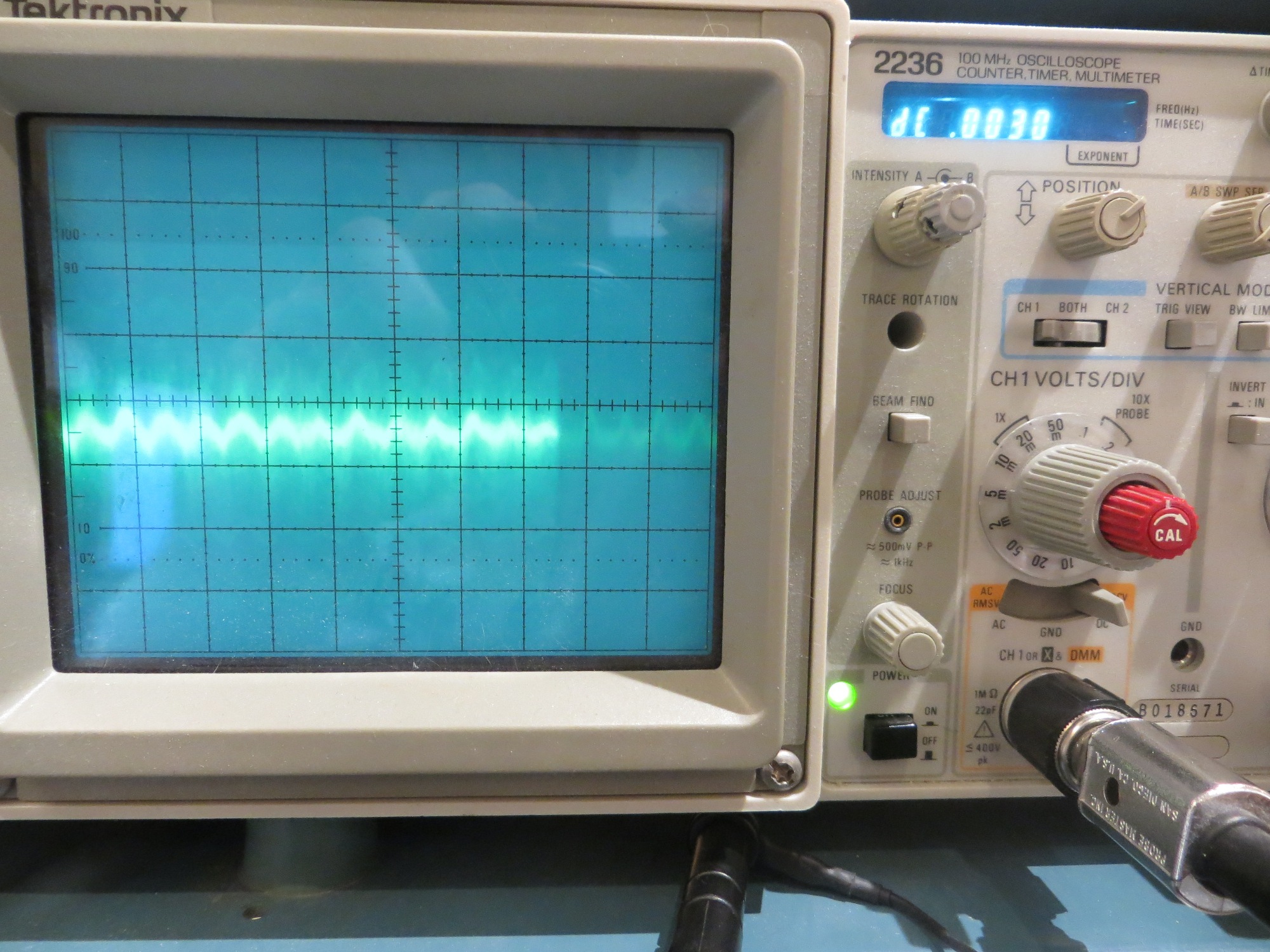
LED monitor circuit audio input. Scope is set to 200mv/div.
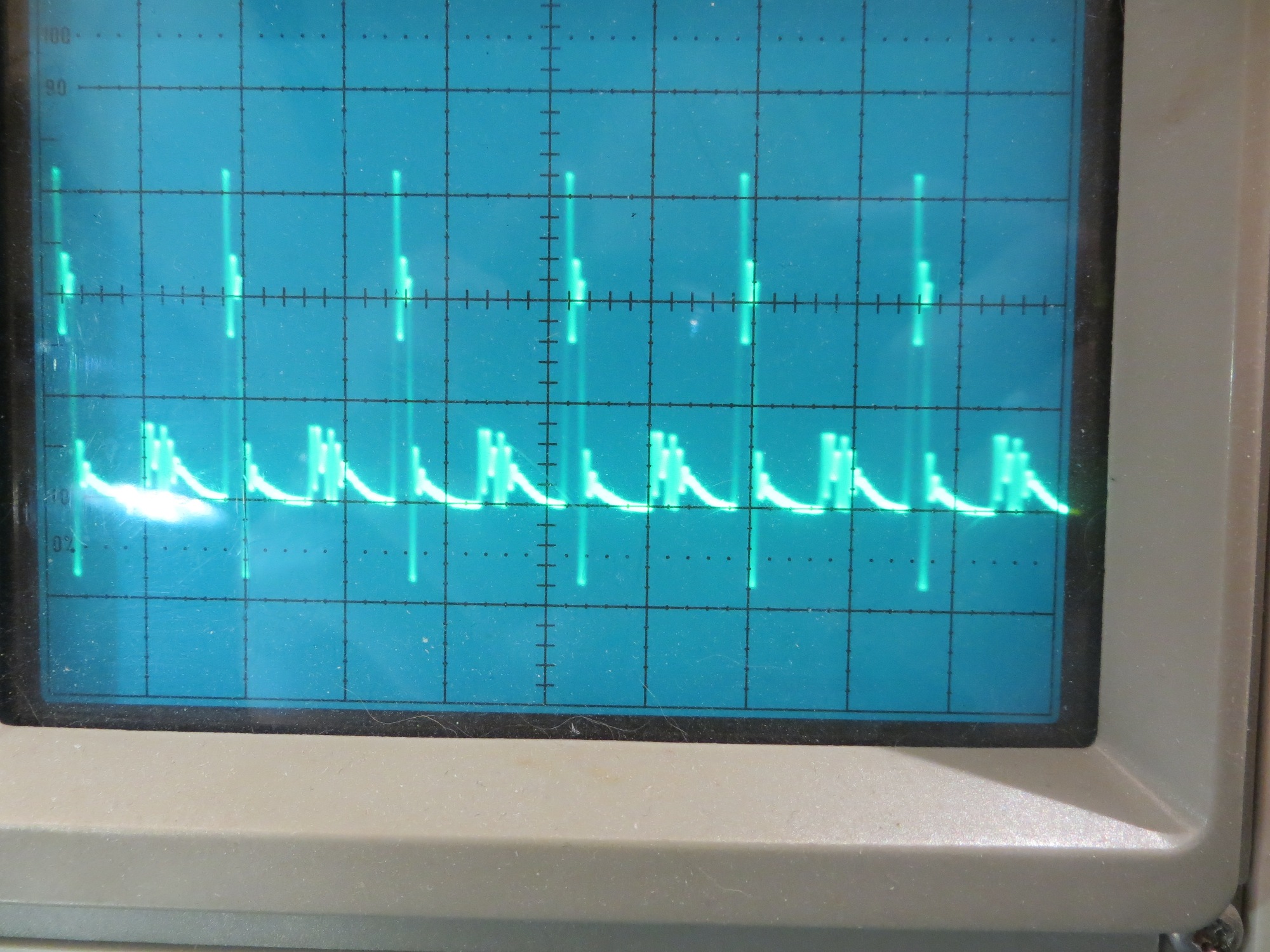
The following photo shows the output. Due to the use of a single-supply op-amp and without any DC bias arrangement, only the positive input signal excursions produce an output – but that’s OK in this circuit as all we are doing is driving an LED.
LED monitor circuit LED drive signal. Only the positive audio transitions produce an output. Scope set to 2V/div
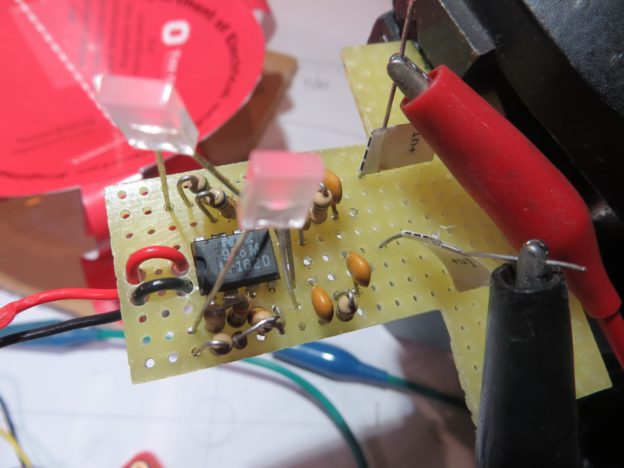
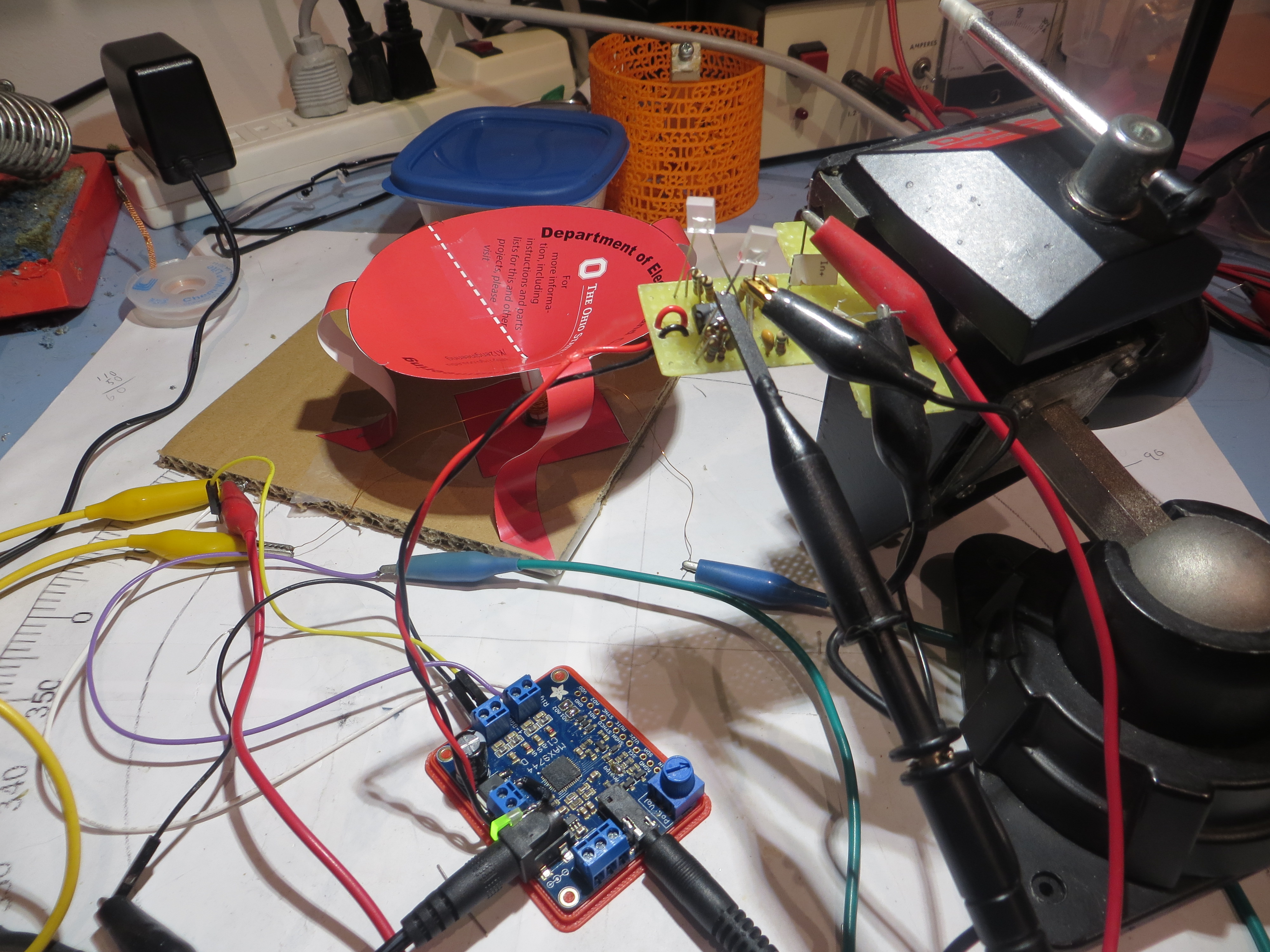
While tweaking the monitor circuit, I had made quite a mess of my little perf-board layout. So, after getting the schematic in good shape I basically tore everything down and started over again with the aim of building up the two-channel layout. After everything was done, the result was the circuit shown in the following photo

Two-channel LED monitor circuit detail
two-channel LED monitor circuit in operation with the Adafruit 20W amp and the OSU paper speaker
After re-working the perf-board layout, adding the second channel, and carefully checking the wiring against the circuit, I was pleased to see that both channels operated as desired, and either channel could easily drive the OSU paper speaker. The following short video shows the speaker being driven by the right channel, and both channel signals being monitored by the LED monitor circuit.
At this point the remaining work is:
- physically cut the perfboard down to a size that will fit into the enclosure, and figure out how it is to be secured.
- Figure out how to mount the channel monitor LEDs so that they can be seen from outside the enclosure. The plan at the moment is to mount them on the outside edge of the left and right screw terminals, respectively, and widen the AUD OUT opening enough so they can be easily viewed from outside.
- Figure out how to route power and audio signals to the LED monitor board without using the external power and audio output screw terminals. The power wiring should be simple, as power and ground are available on the breakout pins provided by Adafruit. However, the audio output signals are more problematic, as it isn’t obvious how to get to these circuit points, and I really don’t want to start drilling holes in a multi-layer PCB. After a careful visual inspection and some probing with my trusty DVM, I think I have located where I can safely tap into the PCB run from the last SMT resistor to the positive audio terminal for each channel – we’ll see!
- Make sure the enclosure top fits OK, and all three LEDs are indeed visible.
- Install semi-permanent L/R audio output cables with alligator clip terminations. In actual use, I don’t really expect two paper speakers to be connected at once, but I’ll be ready if that situation occurs ;-).
Once I’m sure everything is working OK and that the whole thing won’t die on me the first time someone looks at it sideways, then the plan is to volunteer for an upcoming speaker fabrication session and try the amp in the ‘real world’. If it works as I fully expect it to, then the idea is to donate two or three to the OSU Engineering Outreach program, in the name of my company (EM Workbench LLC). Stay tuned!
Frank
Pingback: OSU/STEM Outreach Speaker Amplifier Project, Part III - Paynter's Palace