
Posted July 06, 2016
In my last post on this subject, I had used my newly-completed Magnetometer Calibration Tool to generate calibration factors for my HMC5883L-based ‘Mongoose IMU board, and compare the ‘raw’ vs ‘calibrated’ performance in a ‘free-space’ (actually my wood lab workbench) environment. The result of the comparison showed that the ‘calibrated’ performance was pretty much unchanged from the ‘raw’ setup, indicating that the test setup (on my wooden workbench) wasn’t significantly affected by ‘hard’ or ‘soft’ interference.
The next step is to mount the Mongoose IMU on Wall-E2, my 4WD wall-tracking robot to see if the magnetometer can be compensated for DC motor magnet fields, power cables, and the like. I decided to start this process by mounting the IMU on a wooden ‘stalk’ on the second deck, to see if this placement would minimize the above interfering effects.
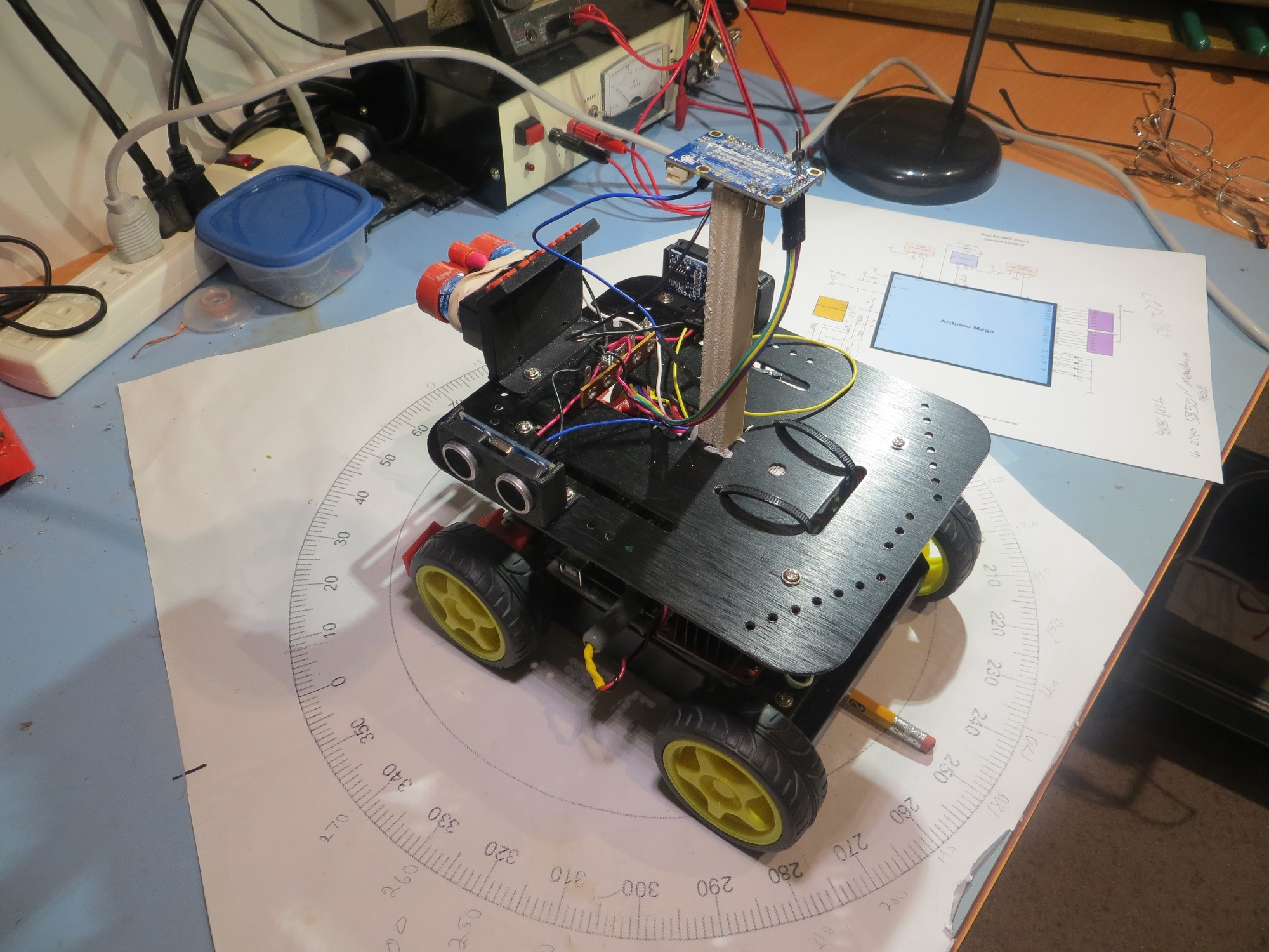
Mongoose IMU mounted on wooden stalk on 2nd deck
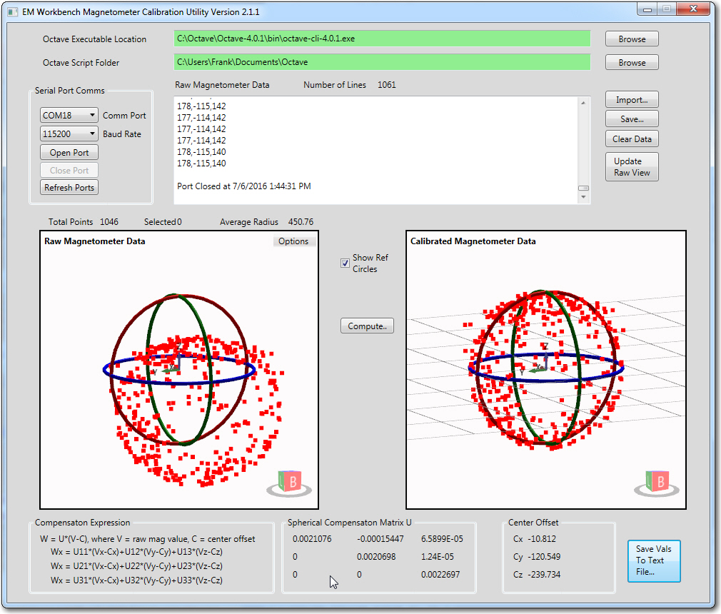
Raw and calibrated data. Reference circles on left have radii equal to average raw value radius. Circles on right all have a radius == 1
The calibration values can now be saved to a text file convenient for transcription into the user’s calibration routine. After doing the save, the text file looks like the following;
|
1 2 3 4 5 6 7 8 9 10 11 12 13 14 |
Magnetometer Compensation Values Saved Wednesday, July 06, 2016 1:50:09 PM Compensation Matrix U11: 0.0021076 U12: -0.00015447 U13: 6.5899E-05 U22: 0.0020698 U23: 1.24E-05 U33: 0.0022697 Center Offset Cx: -10.812 Cx: -120.549 Cx: -239.734 |
After copy/pasting the above values into my calibration routine and re-running the data collection exercise but recording the calibrated magnetometer readings instead, I got the following ‘raw’ (calibrated magnetometer data, but displayed in the ‘raw’ view) results.
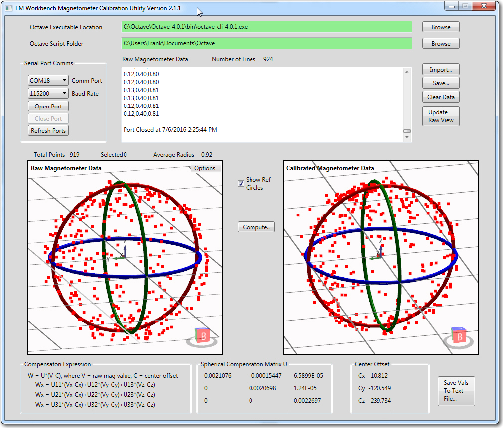
Comparison of new calibrated data from the magnetometer with the results of the Octave calibration algorithm as applied to the old set of raw magnetometer data.
The displayed data in the ‘raw’ view is new magnetometer data after being calibrated with the results of the first run. The circle radius on the left is 0.92. The data on the left is the old magnetometer data, calibtrated using the results of the calibration value computation from the first set of raw magnetometer data. As is easily seen from the two views, the calibration values generated by the Octave program produce very good ‘on-the-fly’ calibration results.
After calibration, I re-ran the heading performance tests (main power ON, but no drive to the motors), with the following results
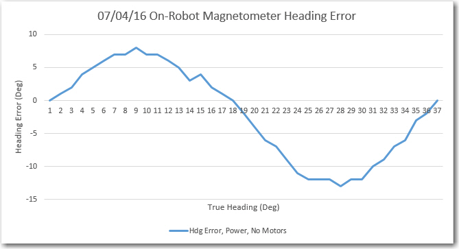
Stalk-mounted magnetometer heading error, main power, no motor drive
The next step is to repeat this experiment with the motor drives enabled. Here’s the results of a quick run. With the motors enabled, I held Wall-E2 so that it’s wheels didn’t quite touch the surface, and slowly rotated the robot 360 clockwise, starting at the same point (nominally 0 deg as reported by the Mongoose IMU) as in the above plot.
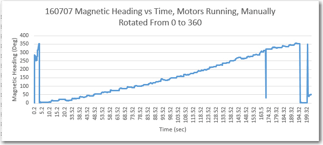
Manually rotated over 360 degrees with motors running. Mongoose stalk mounted on 2nd deck
As shown in the plot above, the headings reported by the Mongoose IMU increased monotonically as the robot was rotated clockwise from nominal zero. Although just a preliminary result, it is actually quite encouraging, as it indicates that running the motors doesn’t significantly affect the heading value reported by the Mongoose IMU.
Today I had the chance to perform a ‘motors running’ heading error experiment with the stalk-mounted Mongoose IMU. The robot body was placed on a small plastic box such that the wheels were free to turn without touching the workbench. Then it was manually rotated in 10 deg increments as before. The experimental setup and the results are shown below.
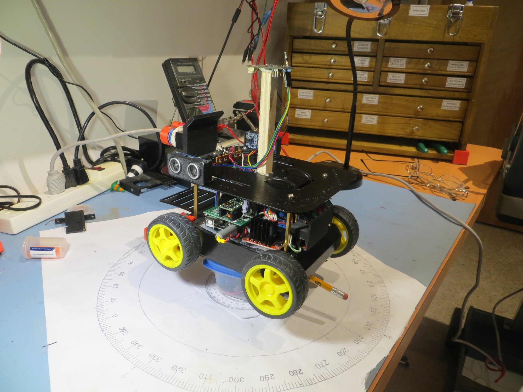
Test setup for the “Power and Motors” IMU heading error experiment.
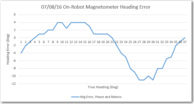
Stalk-mounted Mongoose IMU, with power and motor drive enabled.
Comparing the heading error plots, it is pretty clear that enabling the motors does not significantly affect the stalk-mounted IMU. If I wanted to leave the IMU mounted on the stalk, it appears that I could expect to get reasonable, if not spectacularly accurate, magnetic heading readings ‘in real life’.
However, I really don’t want to leave the IMU mounted on a stalk, so the next step in the process will be to replace the stalk mounting arrangement with a more ‘streamlined’ mounting setup. For this I plan to use the mounting bracket I printed up for the original front-mounted setup (see image below), but attached to the 2nd deck vs the 1st.
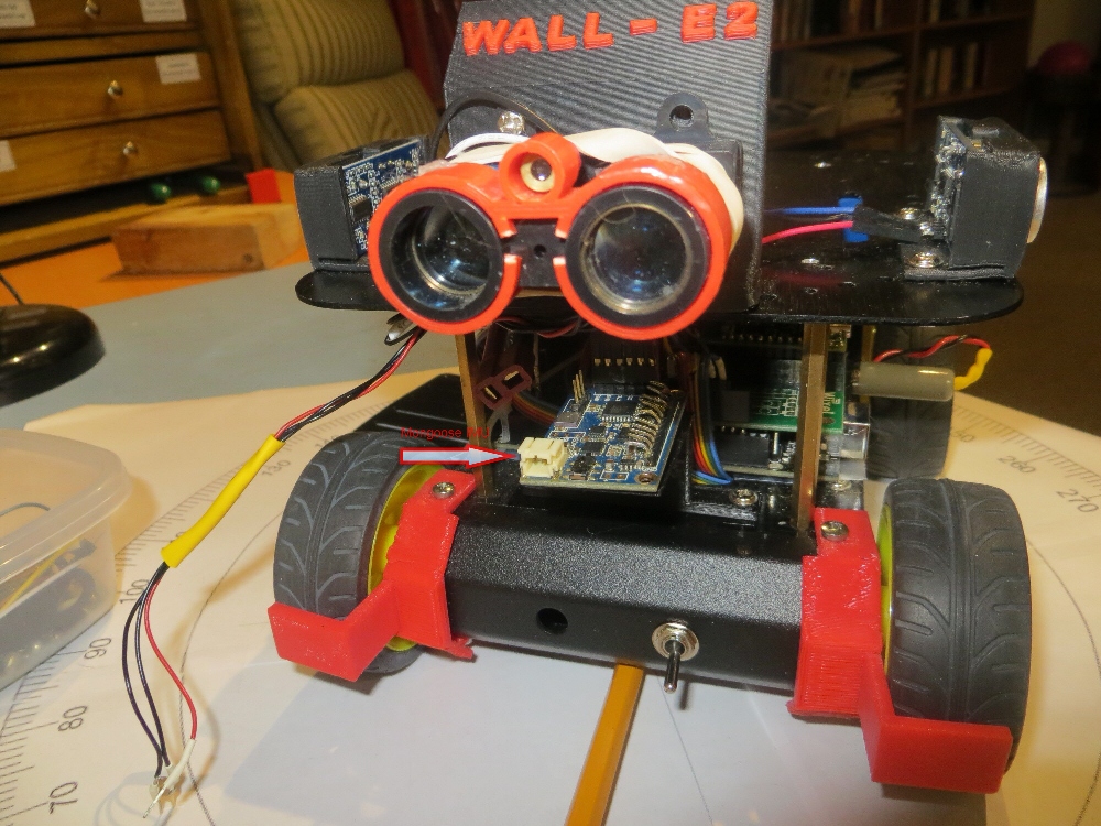
Original mounting location for the Moongoose IMU (arrow points to the IMU)
Pingback: Giving Wall-E2 a Sense of Direction, Part VII - Paynter's Palace