Posted 03/20/16
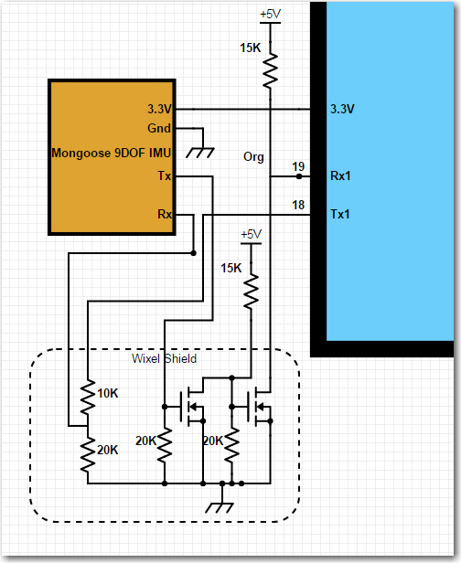
In my last post, I described my efforts to integrate a CK Devices Mongoose 9DOF IMU module into my Wall-E2 wall-following robot. In that post, I had collected a set of azimuth (heading) data from the Mongoose showing that the Mongoose was operating properly and that significant error compensation was possible using a simple sine function. This led me to believe that it would be feasible to install the Mongoose on the robot and create a similar compensation function. Unfortunately, that turned out not to be the case. When I collected a similar set of heading data in the installed case, the data showed non-linear behavior for which function-based compensation would be difficult, if not impossible to achieve.
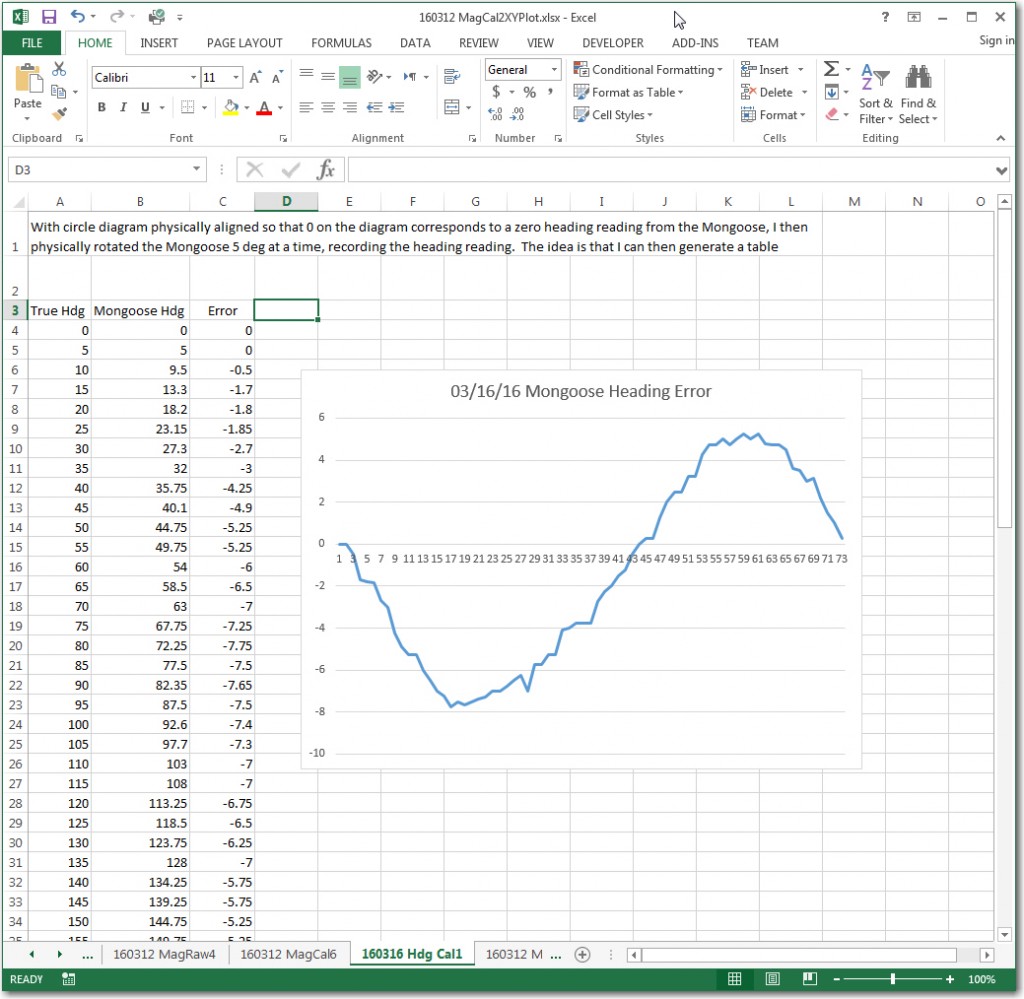
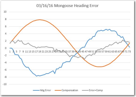
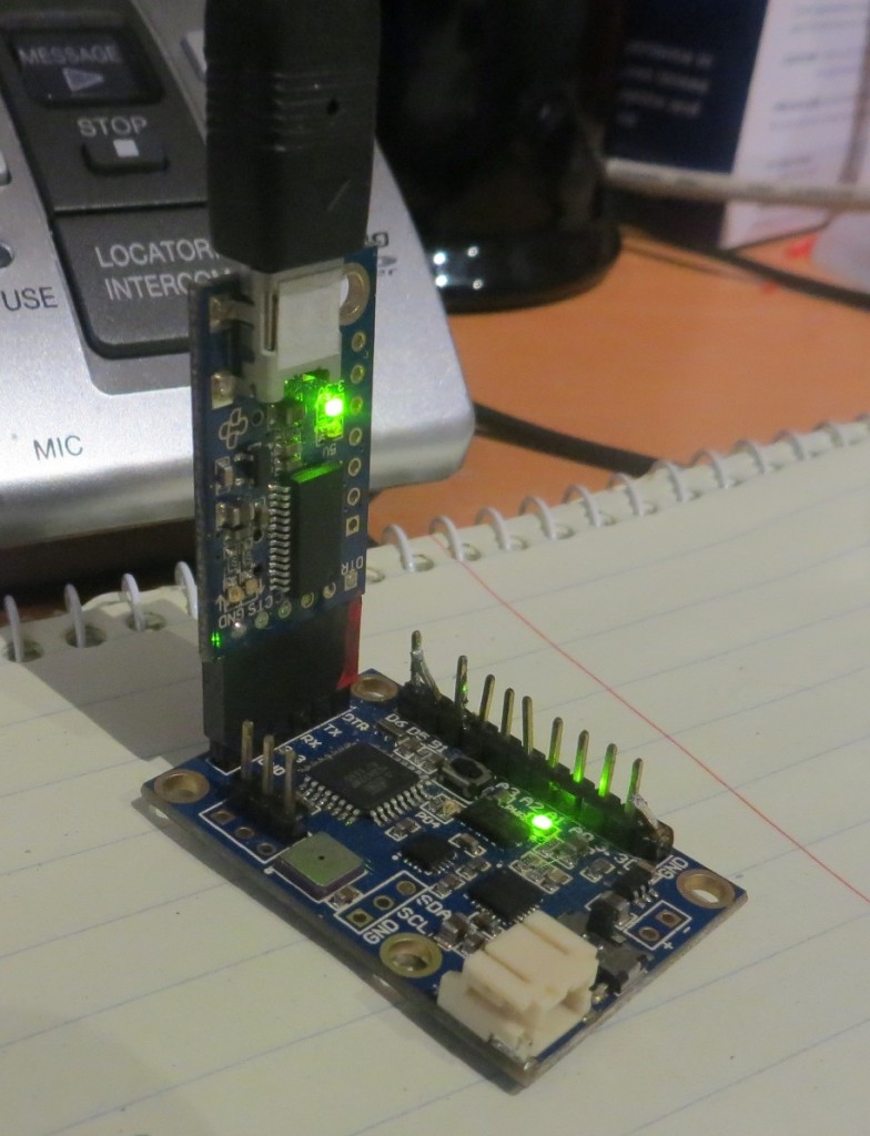
The image below shows results from the ‘bare’ (desktop) uninstalled configuration, where it is clear that the Mongoose raw heading values closely follow the actual magnetic heading, and that a simple sine function is sufficient to reduce heading error to approximately +/- 2 deg.
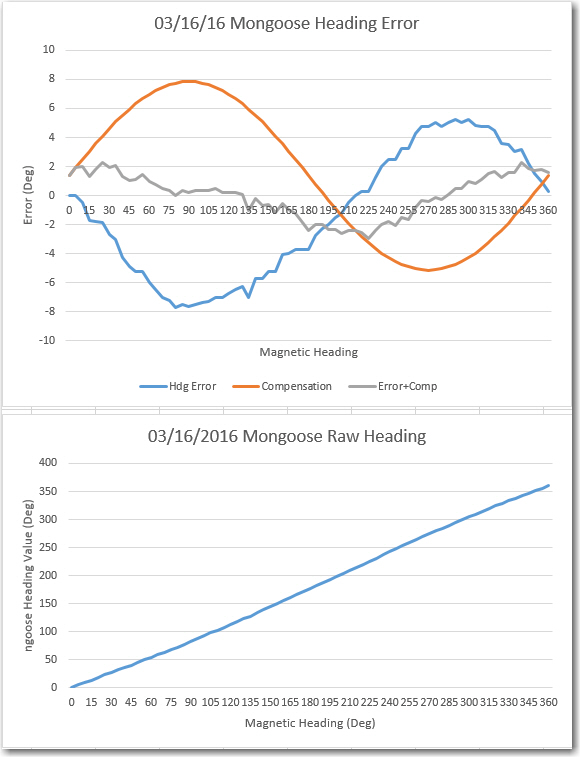
Mongoose Mag Heading & Error on desk before installation on robot
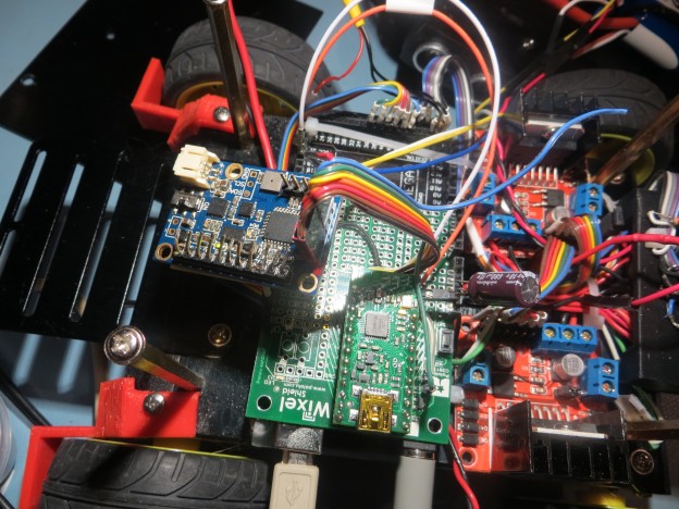
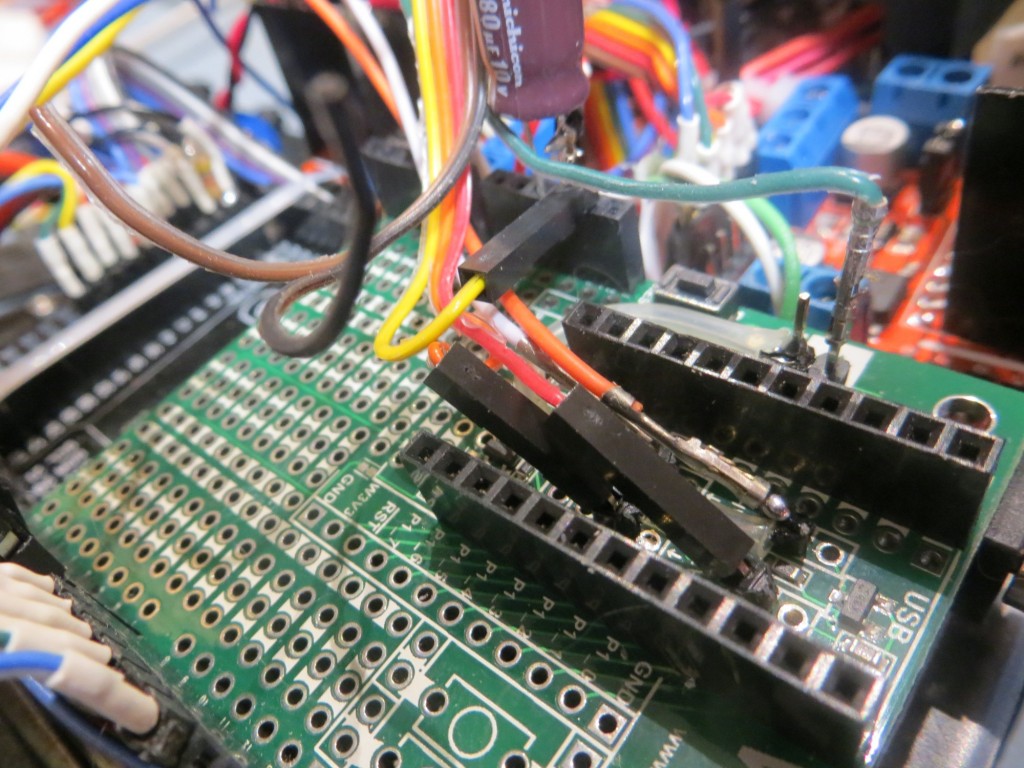
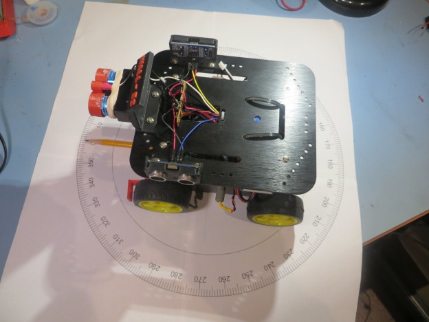
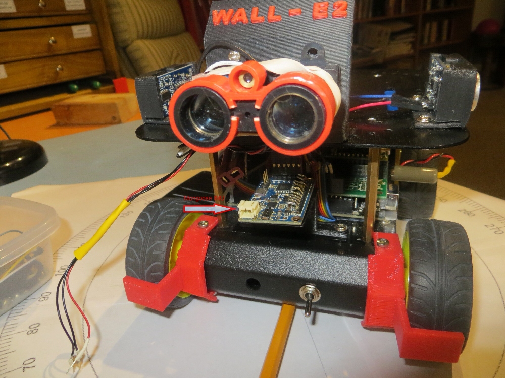
The next set of images shows the Mongoose installed on the robot between the upper and lower decks. The idea was to place the Mongoose in a location reasonably well protected physically, but away from high-current elements. I also wanted to avoid placing it on the upper deck to avoid the additional inter-deck wiring and attendant maintenance/troubleshooting complexity.
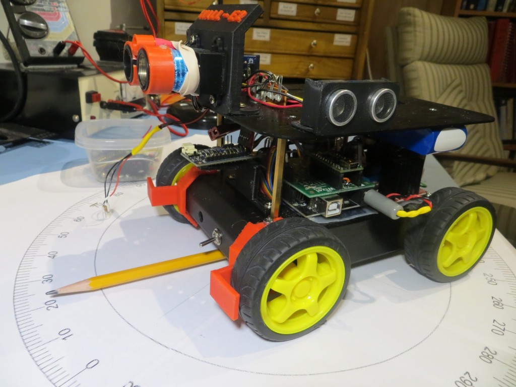
Mongoose installed on robot, side view
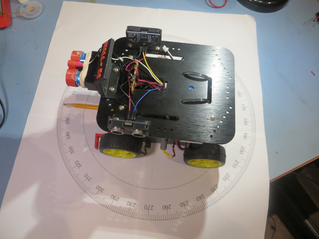
Mongoose installed on robot, top view
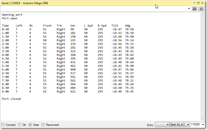
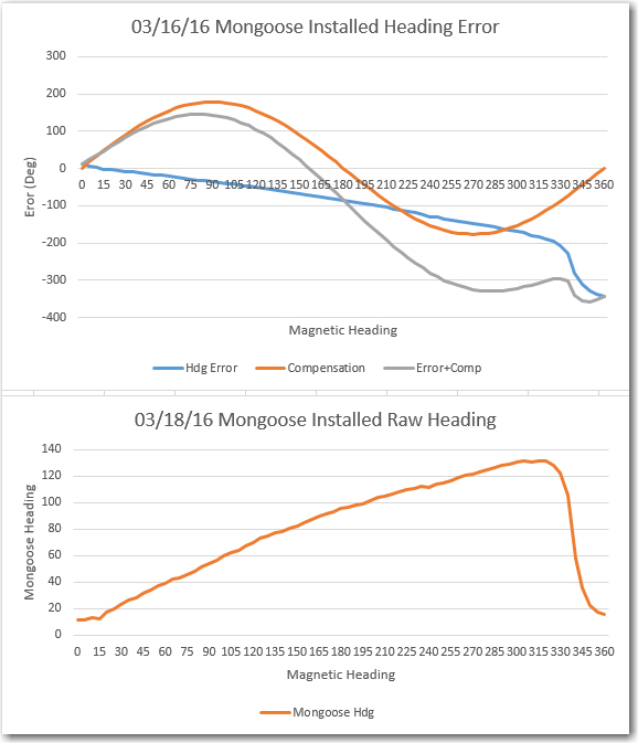
After installation, the same set of measurements were taken, with the results shown in the following plots. As can be seen, the Mongoose heading readings in this case are hugely different than the desktop run. Instead of being able to compensate the heading error to within +/- 2 deg, the compensated error is greater than the uncompensated one! Looking at the Installed Raw Heading plot, it appears that the readings are relatively linear (but heavily suppressed) out to about 315 deg, where something bad happens and the reported heading falls rapidly to near zero. I made another run in the installed configuration with the magnetometer gain turned down as far as possible, but this did not materially improve the situation. Clearly something on the robot was drastically affecting the Mongoose magnetometer, to the extent that compensation was impossible. Moreover, due to the retrograde readings between 315 and 360 degrees, even a lookup table solution seems problematic.
As I often do when faced with what appears to be an insurmountable obstacle, I tabled the problem and did something else for a while and let my subconscious work on the problem for a while. After a couple of days of this, I decided to go back to the uninstalled (desktop) case, re-establish my measurement baseline, and then see if I could determine what on the robot was causing such huge magnetic heading variations. After playing around for a while, I was able to determine that the cause of the problem was the permanent magnets in the DC wheel motors – well DUH!! After smacking myself on the forehead a couple of times for not thinking of this days ago, I realized that I had carefully determined that Wall-E’s chassis was constructed of aluminum that shouldn’t (I thought) cause problems with the magnetometer, forgetting entirely the fact that in addition to not affecting the magnetometer, it also wouldn’t shield the magnetometer from the strong magnetic fields generated by the motor magnets – oops!
So, what to do? As much as I would like to avoid it, it appears now that the only viable solution (other than abandoning the magnetometer idea entirely) is to put the Mongoose on the top deck, as far away from the motors as possible. I am at least a little optimistic that this will work, for two reasons; with the gain turned down, the Mongoose almost worked where it was, and because mag fields decrease with R3, a few cm could make a significant difference.
Stay tuned!
Frank