Posted 01/12/16
A few weeks ago I had what I thought was a great idea – a way of making Wall-E2 react more intelligently to upcoming obstacles as it tracked along a wall.
As it stood at the time, Wall-E2 would continue to track the nearest wall until it got within a set obstacle clearance distance (about 9 cm at present), at which point it would stop, backup, and make a 90-deg turn away from the last-tracked wall direction. For example, if it was tracking a wall to its left and detected a forward obstacle within 9 cm, it would stop, back up, and then turn 90 deg to the right before proceeding again. This worked fine, but was a bit crude IMHO (and in my robot universe MY opinion is the only one that matters – Heh Heh!)
So, my idea was to give Wall-E2 the ability to detect an upcoming obstacle early enough so that it could make a smooth turn away from the currently tracked wall so that it could intelligently navigate the typical concave 90-deg internal corners found in a house. This required that Wall-E2’s navigation code recognize a third distinct forward distance ‘band’ in addition to the current ones (less than 9cm and greater than 9 cm). This third band would be from the obstacle avoidance distance of 9cm to some larger range (currently set at 8 times the obstacle avoidance distance).
After coding this up and setting Wall-E2 loose on some more test runs, I was able to see that this idea really worked – but not without the usual unintended consequences. In fact, after a number of test runs I began to realize that the addition of the third distance ‘band’ had complicated the situation to the point where I simply couldn’t acquire (or maintain) a sufficiently good understanding of all the subtleties of the logic; Every time I thought I had it figured out, I discovered all I had done was to exchange one failure mode for another – bummer!
So, I did what I always do when faced with a problem that simply refuses to be solved – I quit! Well, not actually, but I did quit trying to solve the problem by changing the program; instead I put it aside, and began thinking about it in the shower, and as I was lying in bed waiting to go to sleep. I have found over the years that when a problem seems intractable, it usually means there is a piece or pieces missing from the puzzle, and until I ferret it or them out, there is no hope of arriving at a complete solution.
So, after some quality time in the showers and during the ‘drifting off to sleep’ periods, I came to realize that I was not only missing pieces, but I was trying to use some pieces in two different contexts at the same time – oops! I decided that I needed to go back to the drawing board (literally) and try to capture all the variables that comprise the input set to the logic process that results in a new set of commands to the motors. The result is the diagram below.
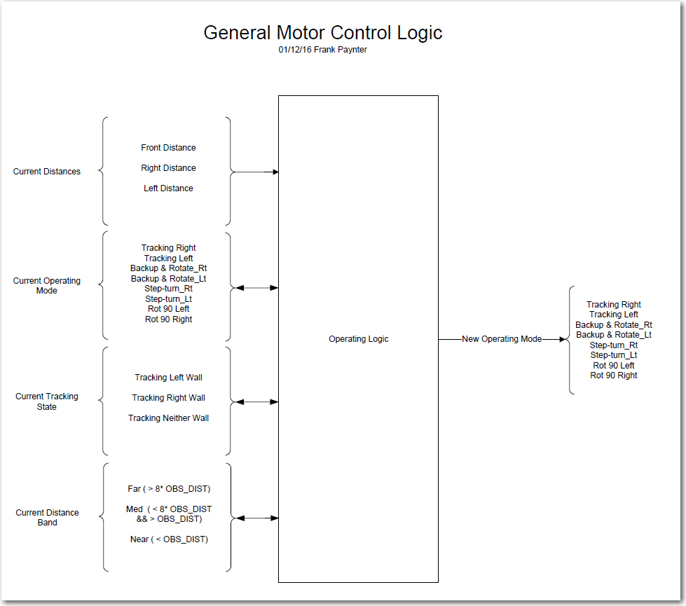
Overall Logic Diagram
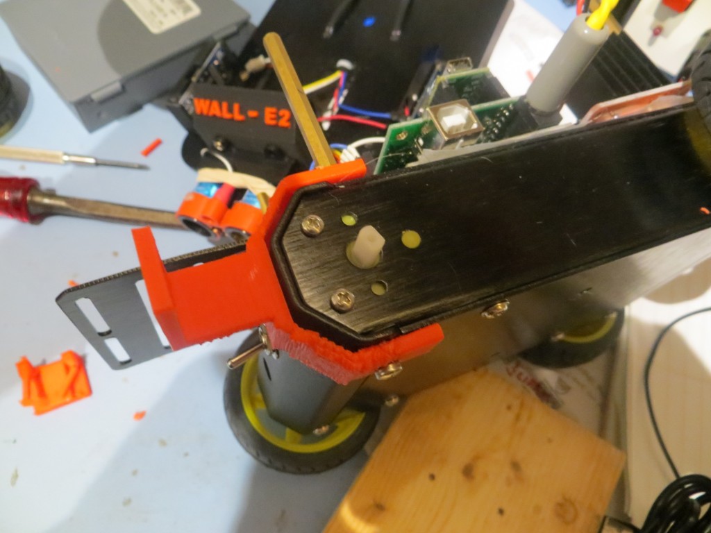
As shown in the above diagram, all Wall-E has to work with are the inputs from three distance sensors. The left & right sensors are acoustic ‘ping’ sensors, and the forward one is a Pulsed Light ‘Blue Label’ (V2) LIDAR sensor. All the other ‘inputs’ on the left side are derived in some way from the distance sensor inputs. The operating logic uses the sensor information, along with knowledge of the previous operating state to produce the next operating state – i.e. a set of motor commands. The processor then updates the previous operating state, and then does it all over again.
The logic diagram breaks the ‘inputs’ into four different categories. First and foremost is the raw distance data from the sensors, followed (in no particular order) by the current operating mode (i.e. what the motors are doing at the moment), the current tracking state (left, right, or neither), and the current distance ‘band’ (less than 9cm, between 9 and 72cm, and greater than 72cm). The processor uses this information to generate a new operating mode and updates the current distance band and current tracking state.
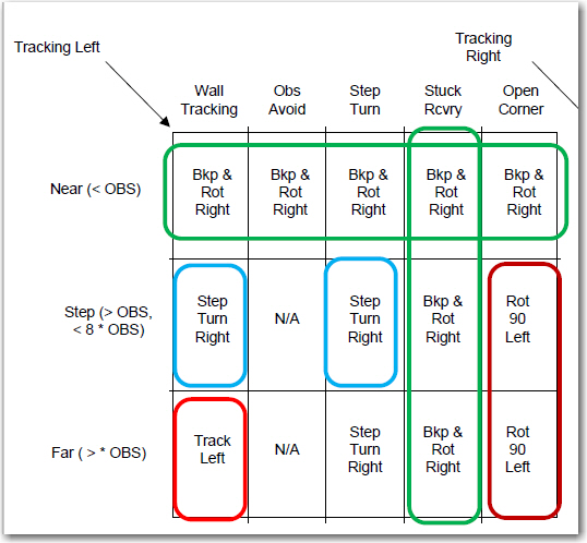
After getting a handle on the inputs, outputs, and state variables, I decided to try my hand at using the Karnaugh mapping trick I learned back in my old logic circuit design days 40 or 50 years ago. The technique involves mapping the inputs onto one or more two-dimensional grids, where every cell in the grid represents a possible output of the logic process being investigated. In it’s ‘pure’ implementation, the outputs are all ‘1’ or ‘0’, but in my implementation, the outputs are one of the 8 motor operations modes (tracking left/right, backup-and-rotate left/right, step-turn left/right, and rotate-90-deg left/right). The full set of Karnaugh maps for this system are shown in the following image.
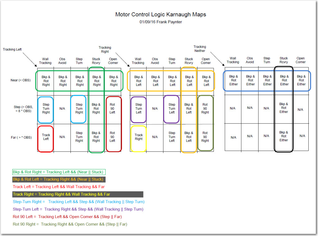
Karnaugh Map using variables from logic diagram
The utility of Karnaugh maps lies in their ability to expose possible simplifications to the logic equations for the various desired outputs. In a properly constructed K-map, adjacent cells with the same output indicate a potential simplification in the logic for that output. For instance, in the diagram above, the ‘Backup-and-Rotate-Right’ output occurs in all four cells in the top row of the ‘Tracking Left’ map (shown in green above). This indicates that the logic equation for that desired output simplifies down to simply “distance band == ‘NEAR’. In addition, the Backup-and-Rotate-Right’ output occurs for all four cells in the ‘Stuck Recovery’ column, indicating that the logic equation is simply “operating mode == Stuck Recovery”. The sum (OR) of these two equations gives the complete logic equation for the ‘Backup-and-Rotate-Right’ motor operating mode, i.e.
Backup-and-Rotate-Right = Tracking Left && (NEAR || STUCK)
The above example is admittedly the least complicated, but the complete logic equations for all the other motor operation modes can be similarly derived, and are shown at the bottom of the K-map diagram above. Note that while for completeness I mapped out the K-map for ‘Tracking Neither’, it became evident that it doesn’t really add anything to the logic. It can simply be ignored for purposes of generating the desired logic equations.
Now that I have what I hope and believe is the complete solution for the level of intelligence I wish to implement with Wall-E2, actually coding and testing it should be MUCH easier. At the moment though, said implementation and testing will have to wait until I and my wife return from a week-long duplicate bridge tournament in Cleveland, OH.
Stay tuned! ;-))
Frank
January 16 Update:
As I was coding up the results of the above study, I realized that the original Karnaugh map shown above wasn’t an entirely accurate description of the problem space. In particular, I realized that if Wall-E2 encounters an ‘open corner’ (i.e. both left & right distances are > max) just at the Far/Near boundary, it is OK to assign this condition to either the ‘Step-Turn’ (i.e. start a turn away from the last-tracked wall) or the ‘Open Corner’ (i.e. start a turn toward the last-tracked wall). And if I were to arbitrarily (but cleverly!) assign this to ‘Step-Turn’, then the K-map changes from the above layout to the revised one shown below, where the ‘Open Corner’ condition has been reduced to just the one cell in the lower right-hand corner of both the left and right K-maps.
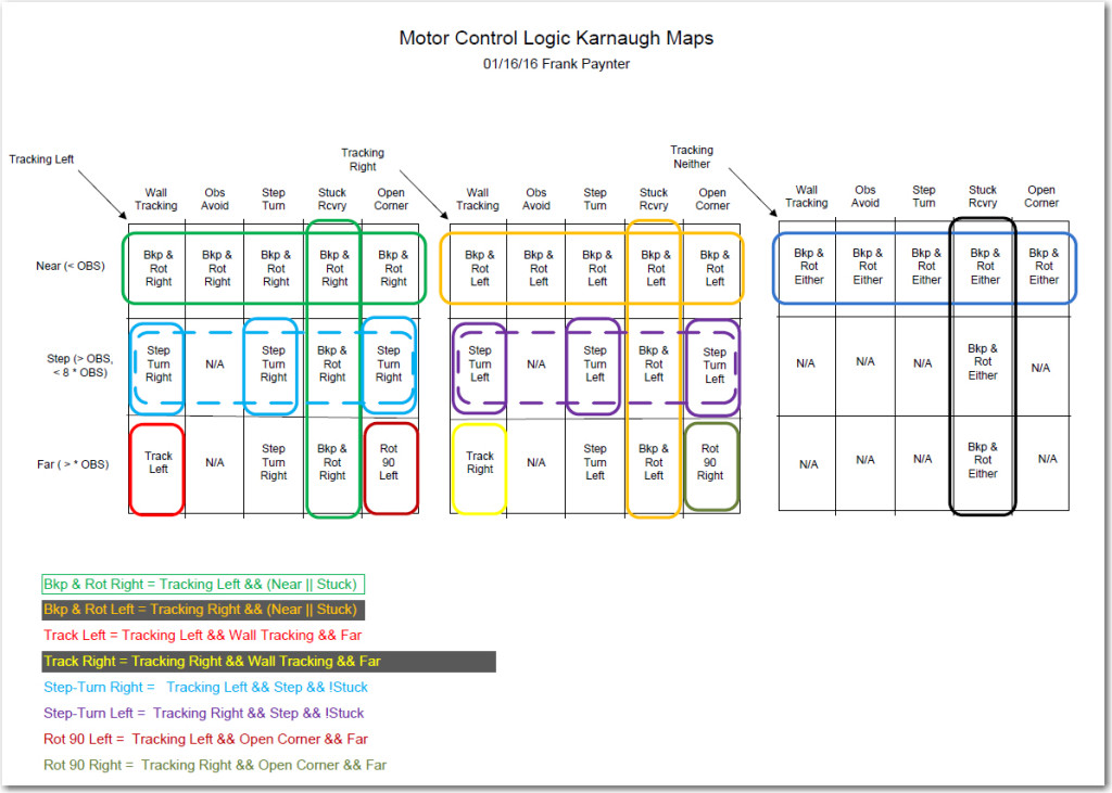
Revised Motor Control Logic Karnaugh Map
So now the logic expressions for the two ‘Open Corner’ motor response cases (i.e. start a turn toward the last-tracked wall) are:
Rotate 90 Left = Tracking Left && Open Corner&& Far
Rotate 90 Left = Tracking Left && Open Corner&& Far
But the other implication of this change is that now the ‘Step-Turn’ expression can be simplified from the ‘sum’ (logical OR) of two 3-term expressions to a single 3-term one, as shown by the dotted-line groupings in the revised K-map, and the following expressions for the ‘Left Tracking’ case:
previous: Step-turn Right = Tracking Left && Step && (Wall Tracking || Step Turn)
new: Step-turn Right = Tracking Left && Step && !Stuck
much easier to implement!
OK, back to coding…..
Frank