Yearly Archives: 2016

Wall-E2 Charging Station Design, Part V

Posted 18 Dec 2016

The new charging system for Wall-E2 consists of three major parts:

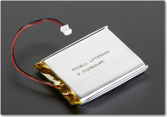
  • The two 3.7V Li-Ion battery packs and battery chargers (one charger for each battery pack)
  • The contact array that connects the charging platform  to the chargers.
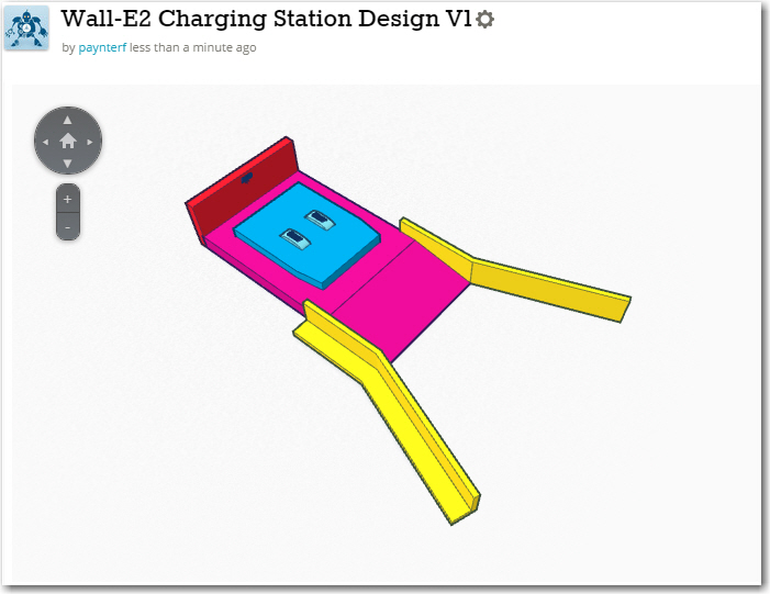
  • The charging platform and charging power supply

I have spent the few days  or so working on the first two items above, building up the battery pack and charging circuit for Wall-E2, and working out the details of the contact array for connecting Wall-E2 to the charging platform.

Charging Module:

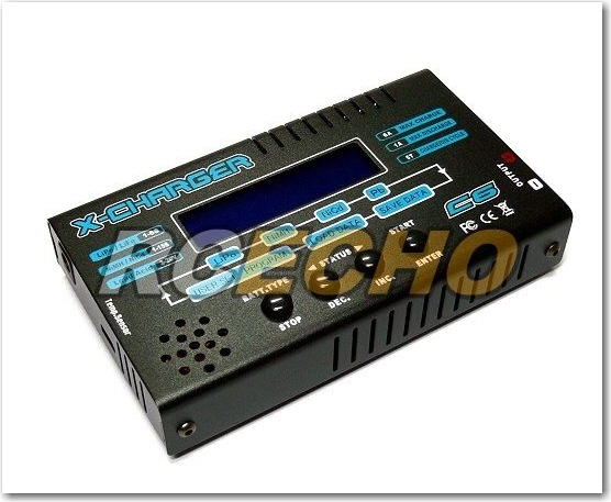
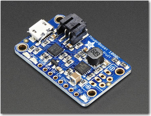
This is actually the third time I have attempted a charging system for a  7.4V Li-Ion battery pack consisting of two 3.7V cells.  The first one was for my original Wall-E, and it is still cooking along.  The second one was for Wall-E2, and it didn’t go as well.  After all the work of building up the module and tucking it into the robot, I discovered that the system just wasn’t robust enough for Wall-E2’s higher power requirements, so I wound up going with a high-current RC battery and an external charger.  This wasn’t really satisfactory either, as the battery pack was just too big and awkward, and having to physically disconnect the pack from the robot to charge it was a real PITA.  Plus, I still harbored the  desire to make Wall-E2 more human-independent by giving it the capability of recharging itself.  So I made another run at the dual-pack charging universe, and this time I found an article by the Adafruit guys  about a ‘simple balance charger’ using two of their Li-Po chargers and a manual 3PDT switch.  This article very closely matched the charger setup I had used previously,  except for one extra pole on the switch.  In the Adafruit circuit, this third pole was used to switch the positive side of the upper 3.7V pack from the load  to the upper charger. My previous designs didn’t have this switch, and on closer examination, I realized that without this third pole, the upper charger might see the entire 7.4V on its output port – oops!  The reason for this is that the chargers aren’t truly isolated from each other – they share a common ground, and when the circuit is in  series (RUN) mode, the upper charger’s plus output is still tied to the upper battery’s positive terminal, while its negative output is still at ground.  This puts the entire  7.4V across the upper charger – a  BAD thing!

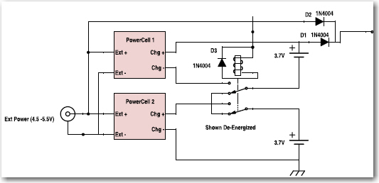
So, I needed a third pole, but although small 3PDT manual switches are easy to find, small/compact 3PDT relays are not.  In my previous designs I had used the very nice Axicom V23105 2PDT telecom  relay, but 3PDT relays in the same form factor were nowhere to be found – grrr!  So eventually I decided to use  two of the Axicom relays and gang the coils to get a 4PDT relay, one pole of which would go unused.  Also, learning from previous mistakes, I made sure I could easily remove/replace the battery packs and the chargers if necessary.  The final charger schematic is shown below, along with some images of the finished charger module.

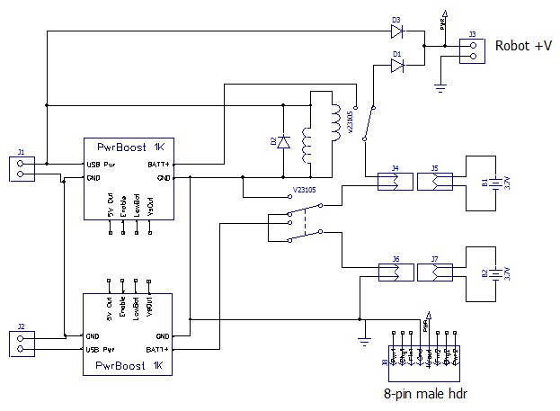
Dual cell balance charger. Note the two Axicom relays ganged to form the required 3PDT switch

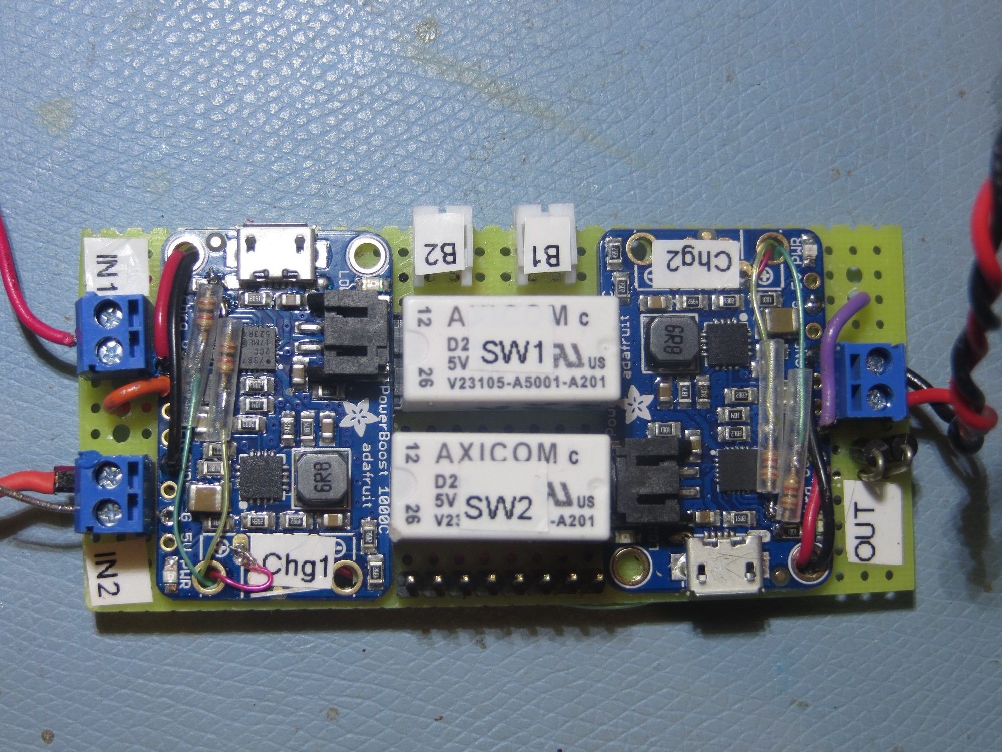
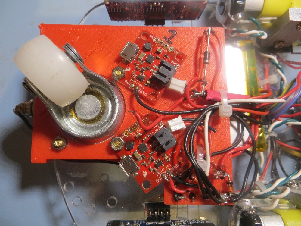
Closeup of the completed charging module. Note the two Axicom relays used to implement a 3PDT switch

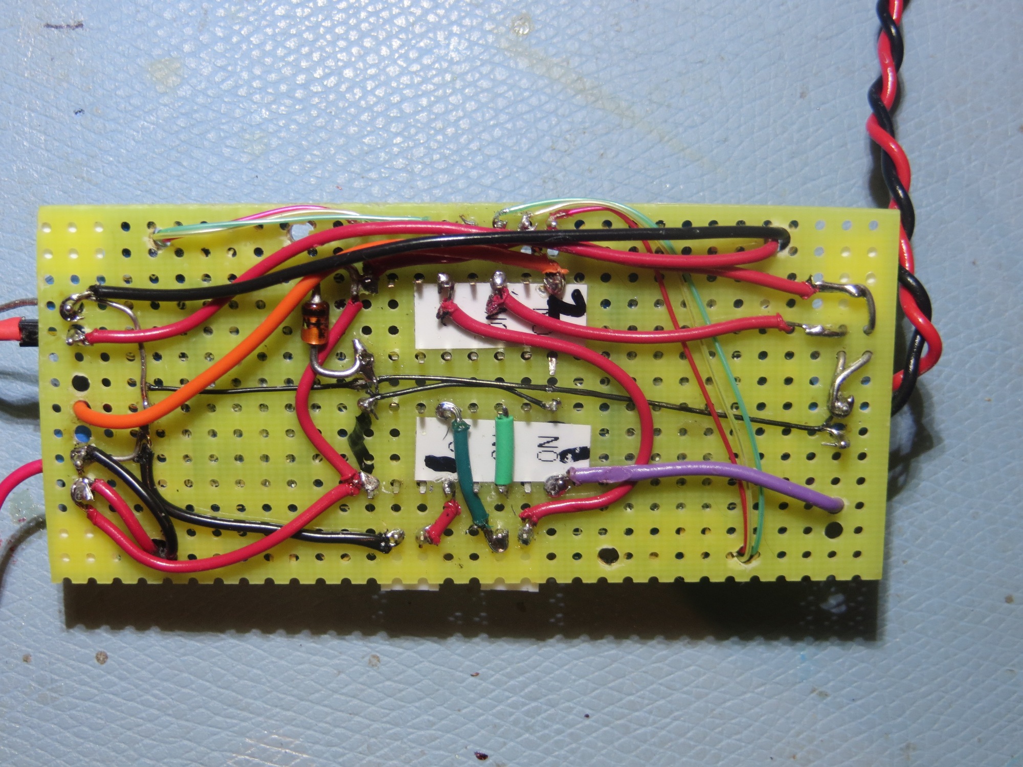
bottom wiring layer of charging module

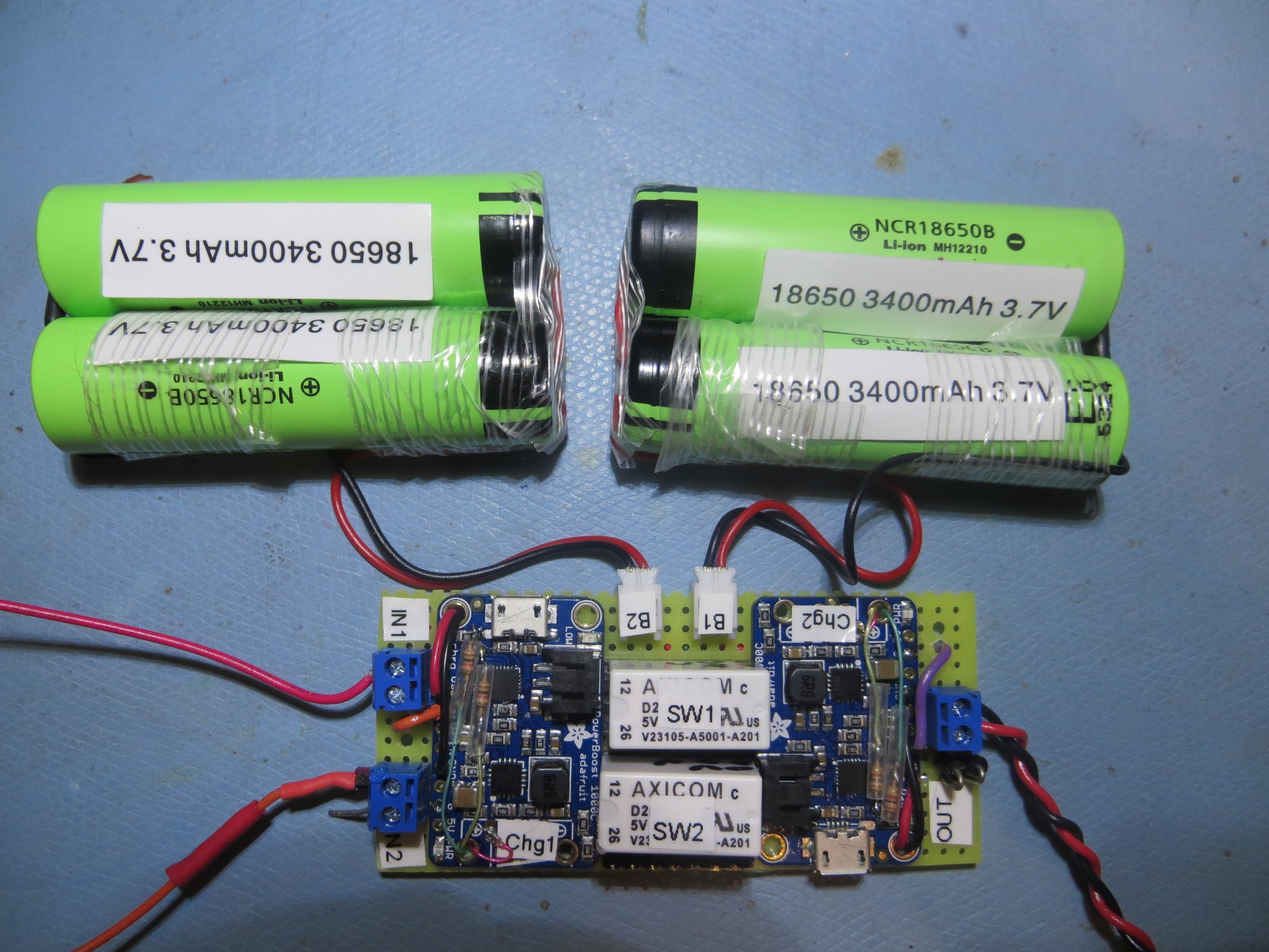
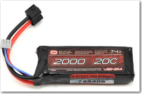
Finished charging module connected to two 2-cell 3.7V battery packs

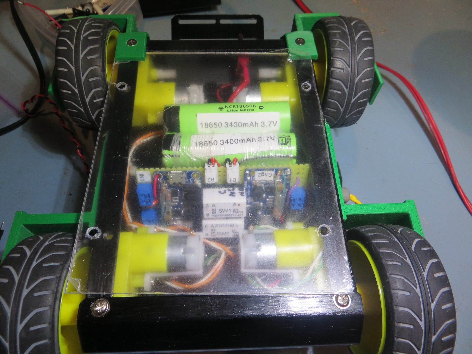
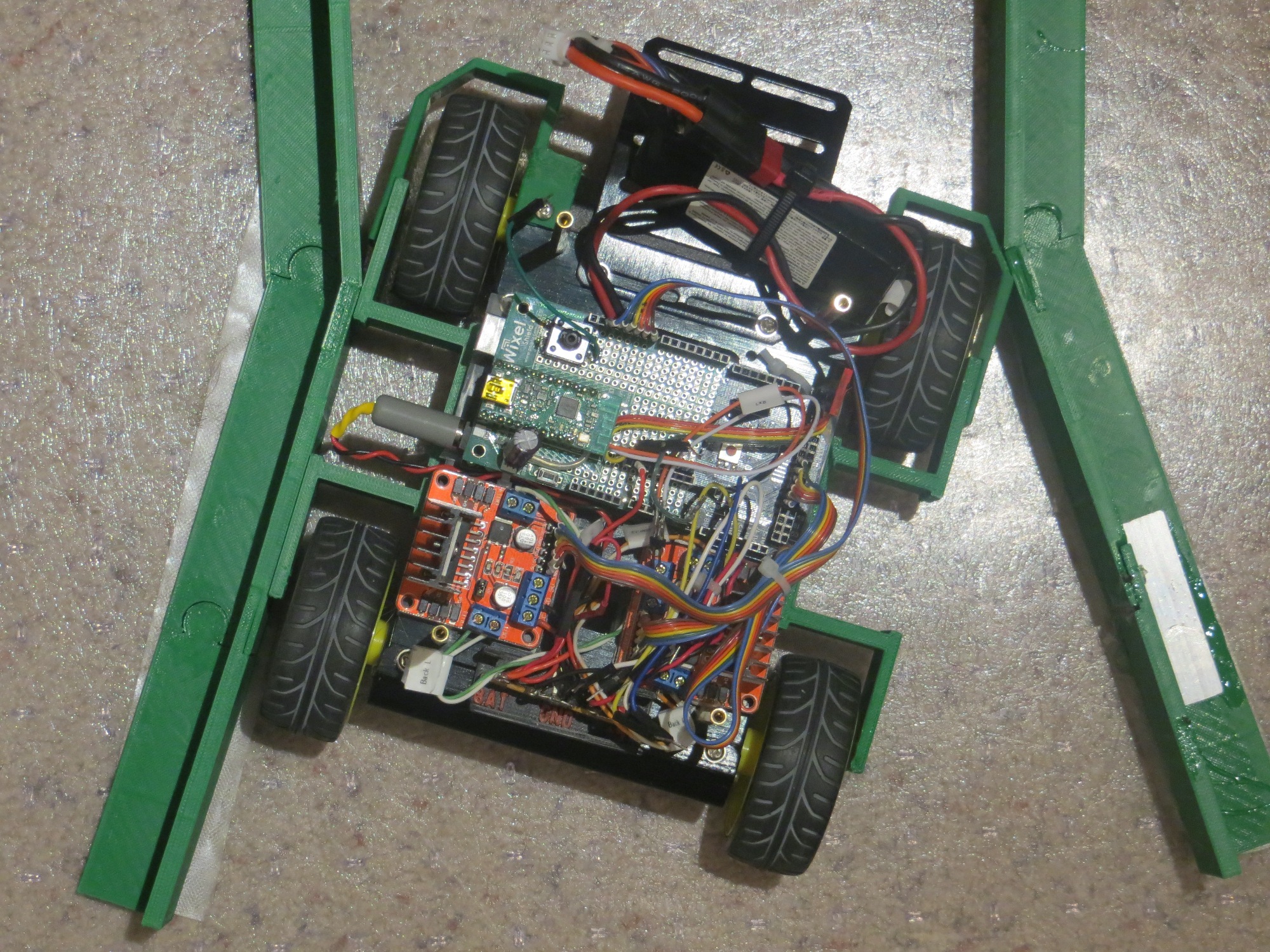
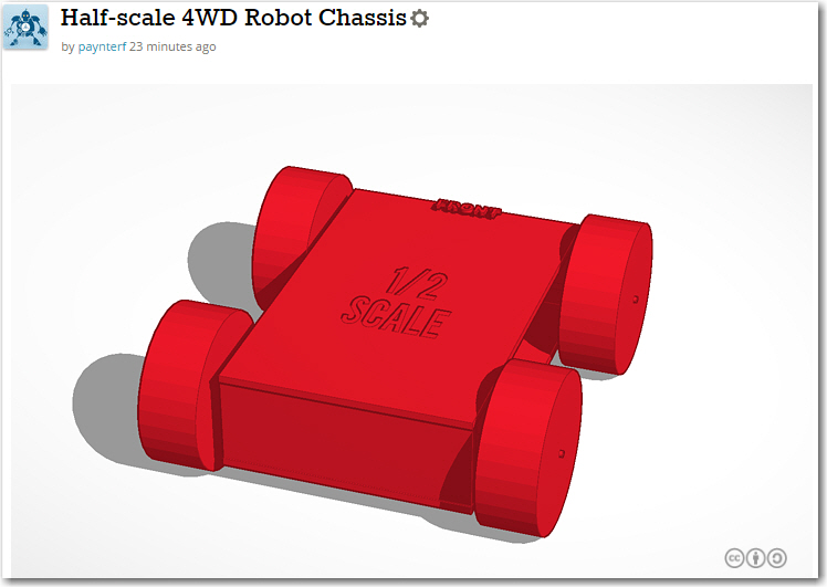
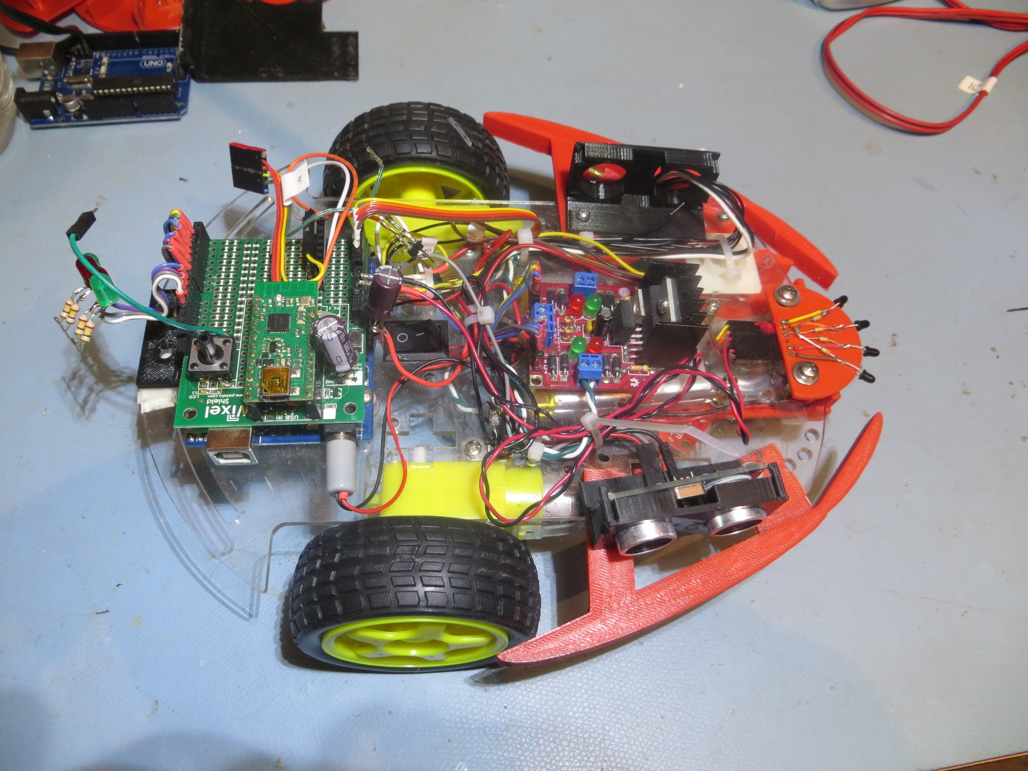
Bottom rear view of 4WD robot showing battery packs and charging module

Signal/Power Contact Array

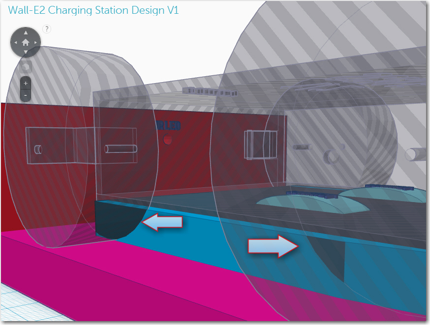
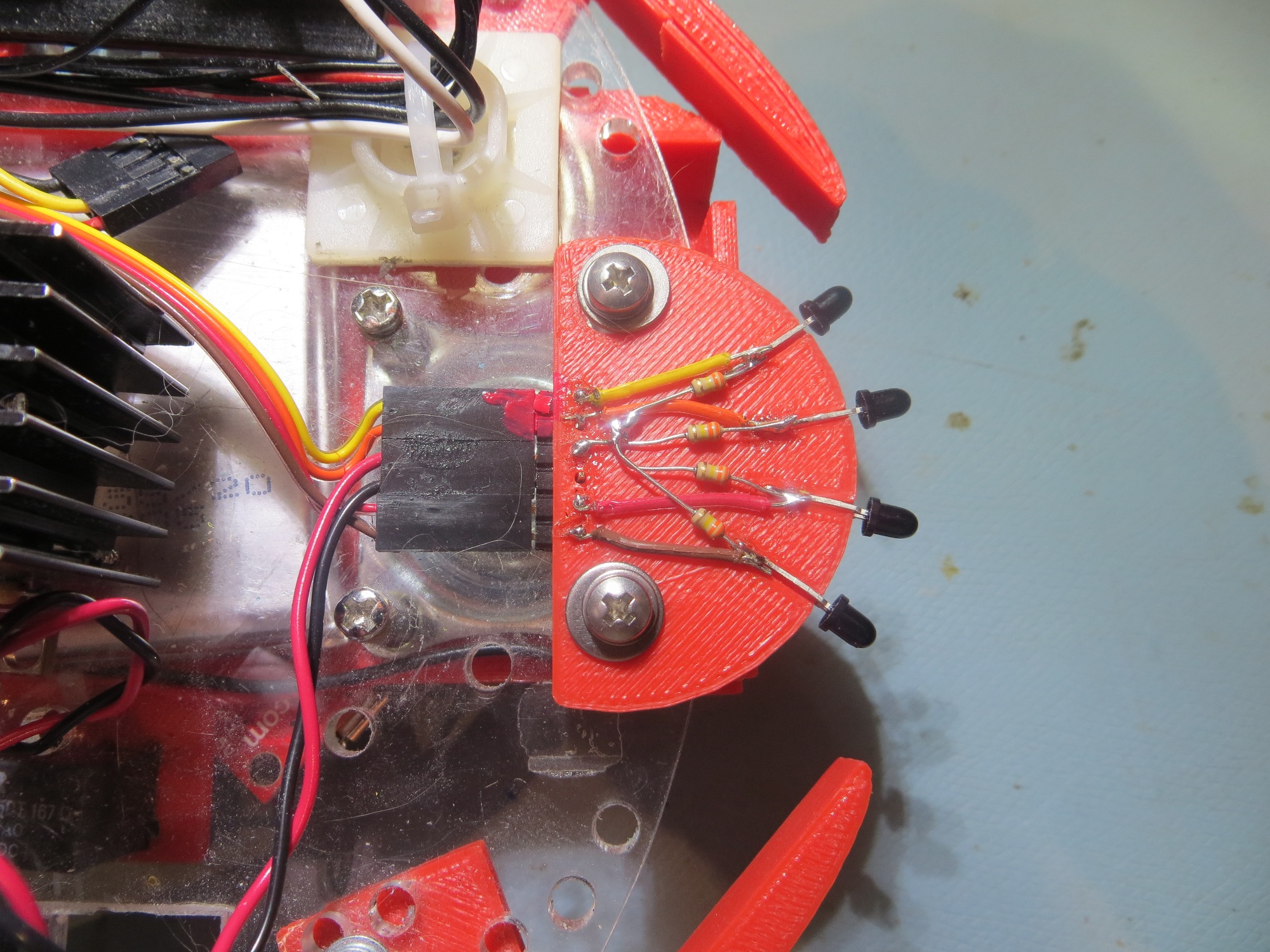
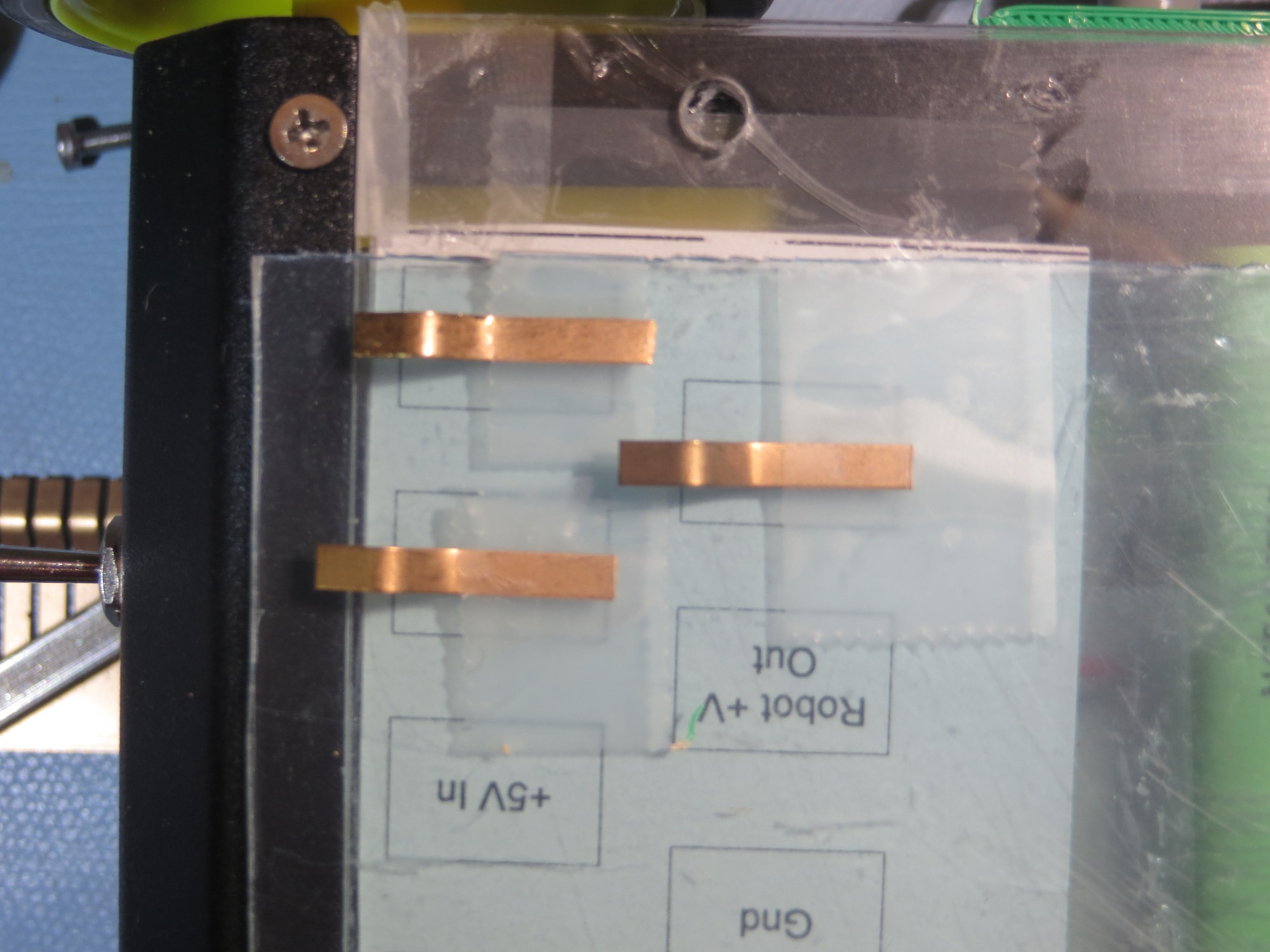
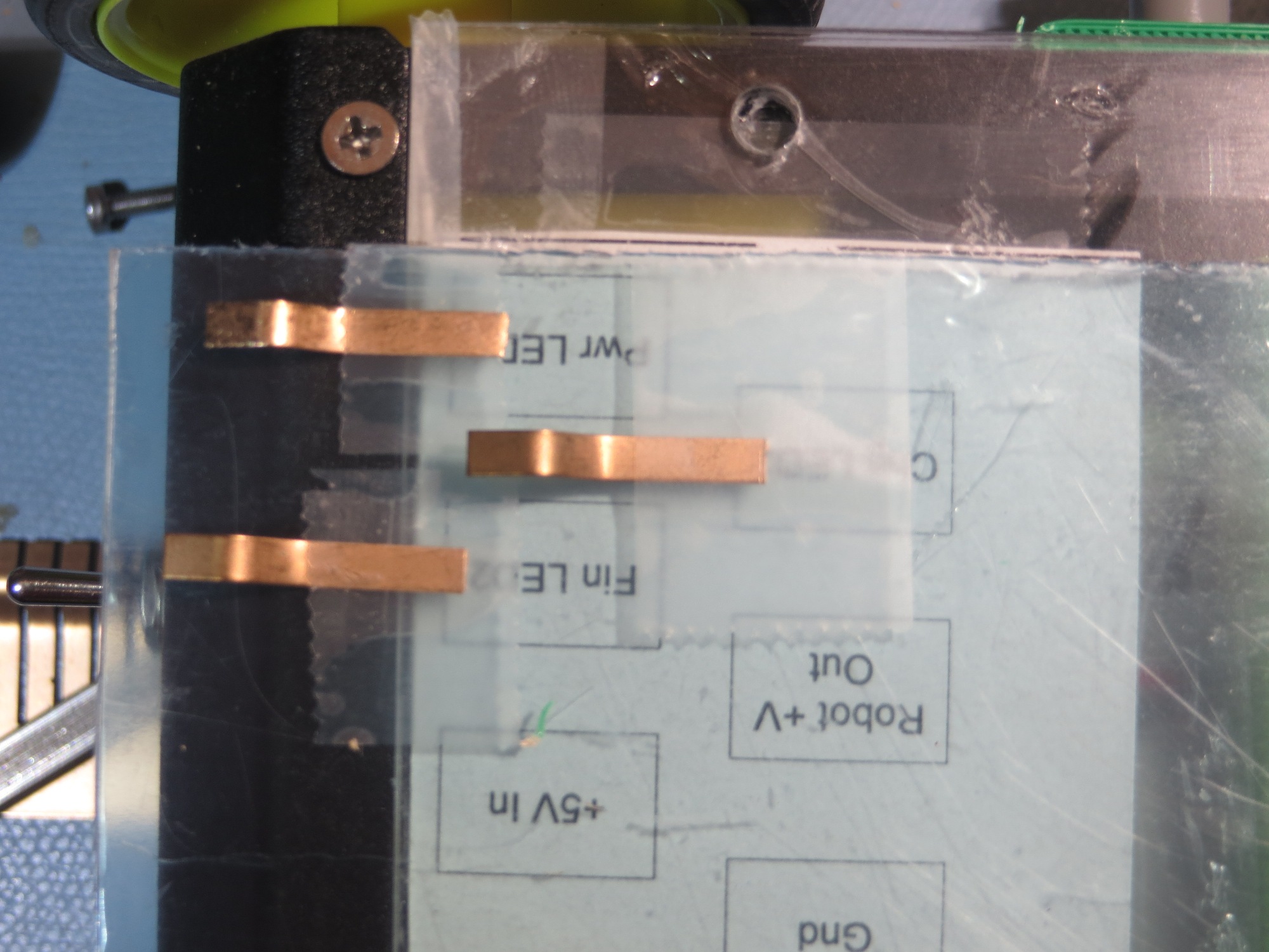
The next challenge was to figure out how to connect the robot to the charging station.  In addition to supplying +5V to the two chargers, I wanted to bring out the power, charging and charge-completed  status signals from both.  This requires a total of 8  contacts ( 6 status signal lines, +5V in, and GND).  I also decided to bring out the power line to the robot, for a total of 9 contacts.  The idea here is to place contact strips on the bottom of the robot, which will make contact with spring-copper sliding contacts on the charging platform.  I played with a number of contact layouts, but ultimately decided on a straight-line array of contacts due to space restrictions in the robot.  In the image below, the contact array layout is shown, with the ‘Pwr LED2’ position partially implemented.


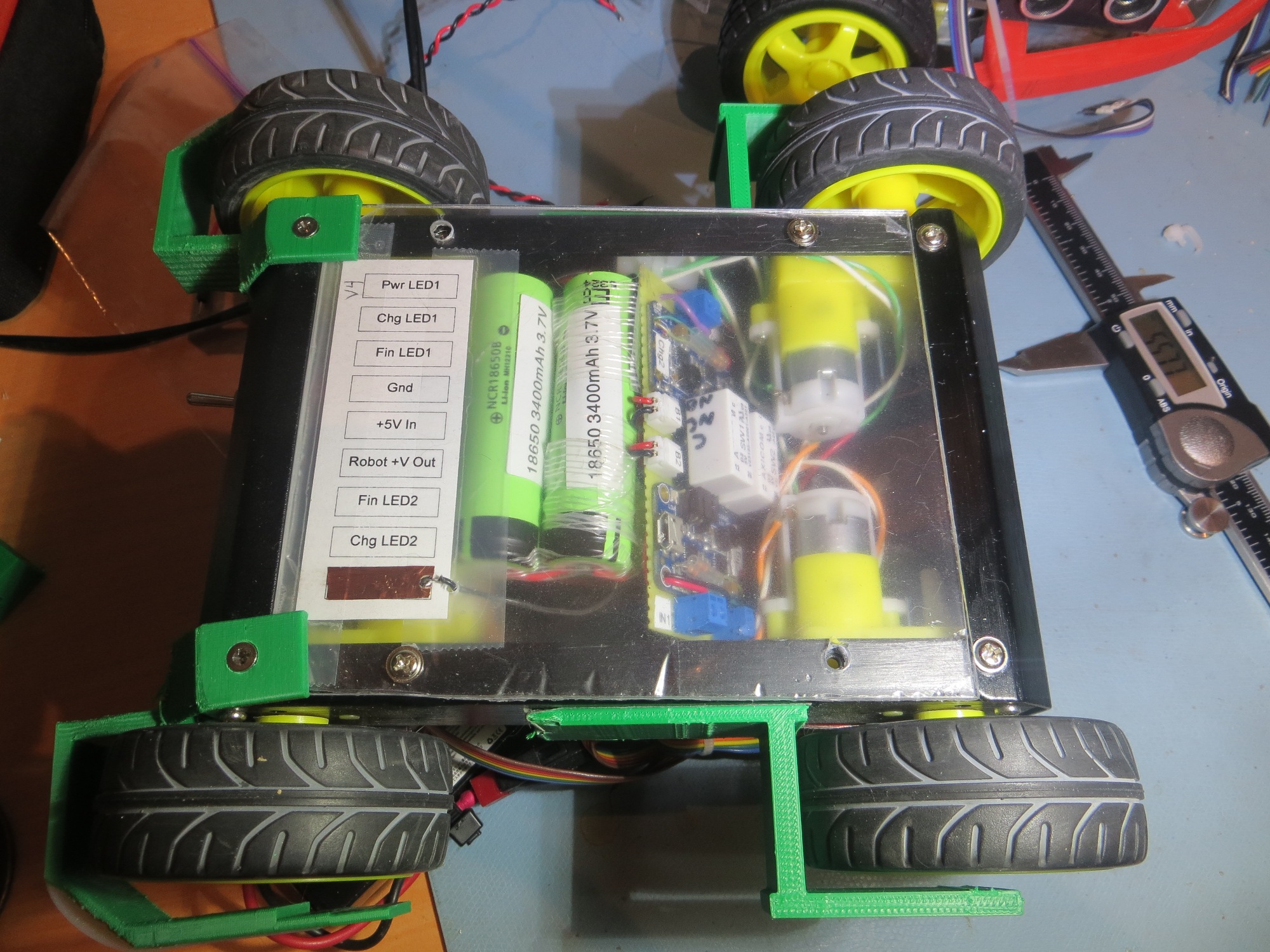
Bottom side view of 4WD robot showing  contact array layout  with the ‘Pwr LED2’ position partially implemented

Some time ago I purchased a length of beryllium-copper finger stock used for fabricating EMI gaskets, with the intention of using the individual fingers as contacts for the charging station.  In order to do this, I needed a way of capturing each finger in the top surface of the charging station.  I went through several iterations as shown below

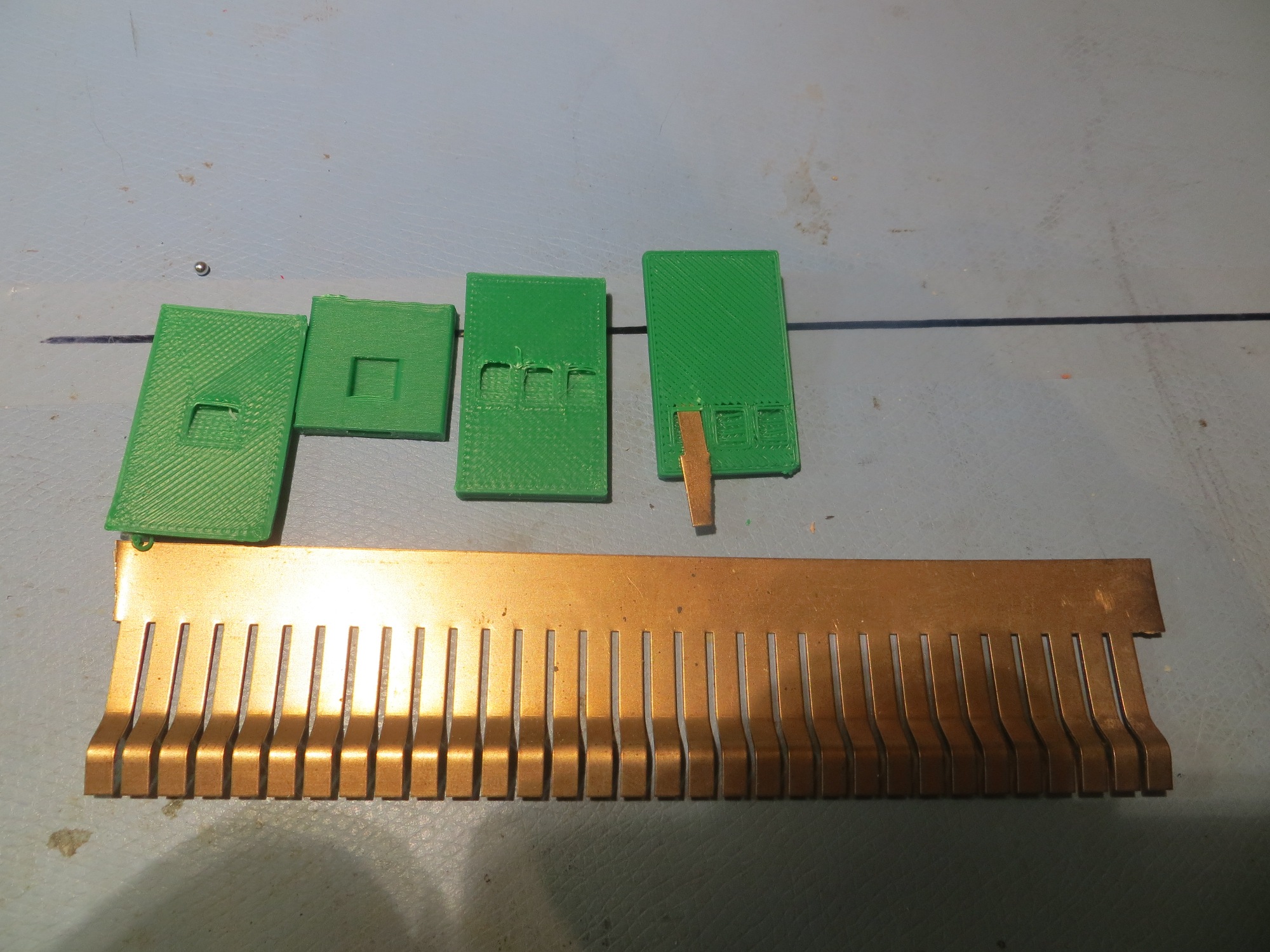
After playing around a bit with  a single contact finger and the contact arrangement shown above, I realized that a small misalignment between the robot and the charging platform could cause a finger to bridge two contacts or even connect with the adjacent circuit.  So, I went back to Visio and redesigned the contact layout, as shown below


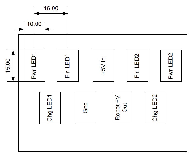
two-row contact layout.  Contacts are 15x10mm with 16mm center-center spacing

As shown in the following photos, this is a much more robust arrangement in terms of contact mis-alignment protection, at the cost of taking up more space on the bottom of the robot

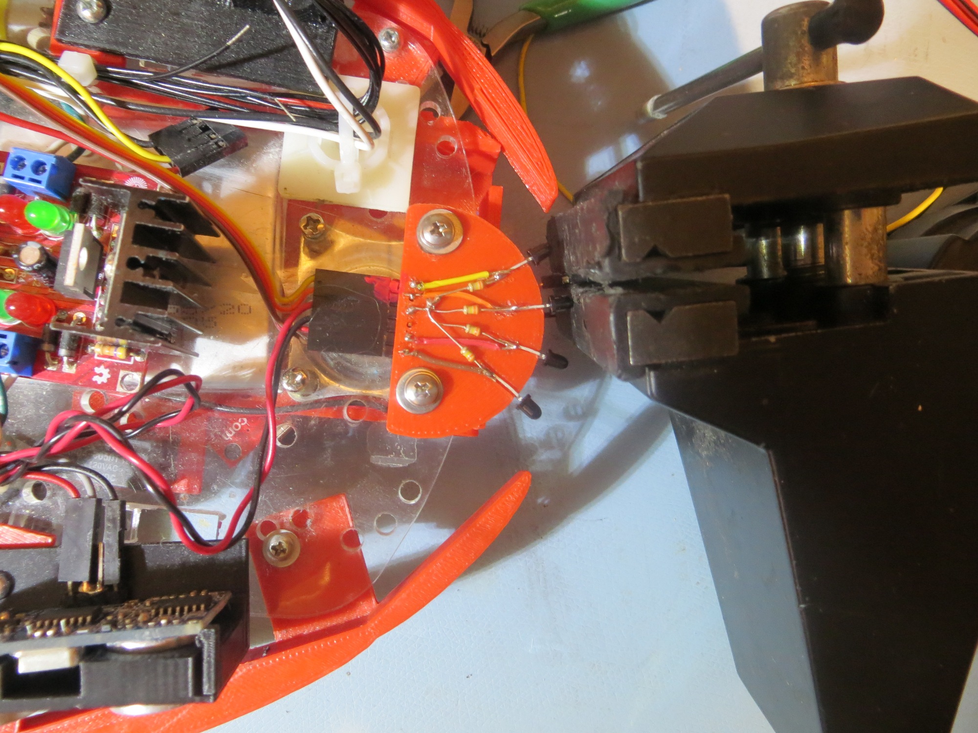
Contacts just prior to engaging

Contacts mis-aligned low

Contacts mis-aligned high

Contacts in the fully engaged position

Contacts just before engaging

Contacts well before engaging

With the above arrangement, there is basically no possibility of a contact finger bridging the gap between two contacts, and even drastic mis-registration of the robot onto the platform will result in correct contact engagement.  That’s my story, and I’m sticking to it! ;-).

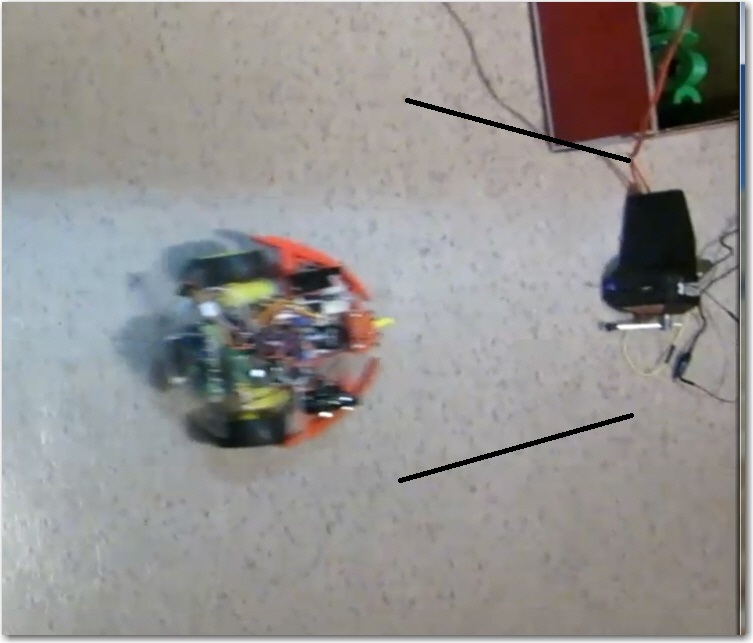
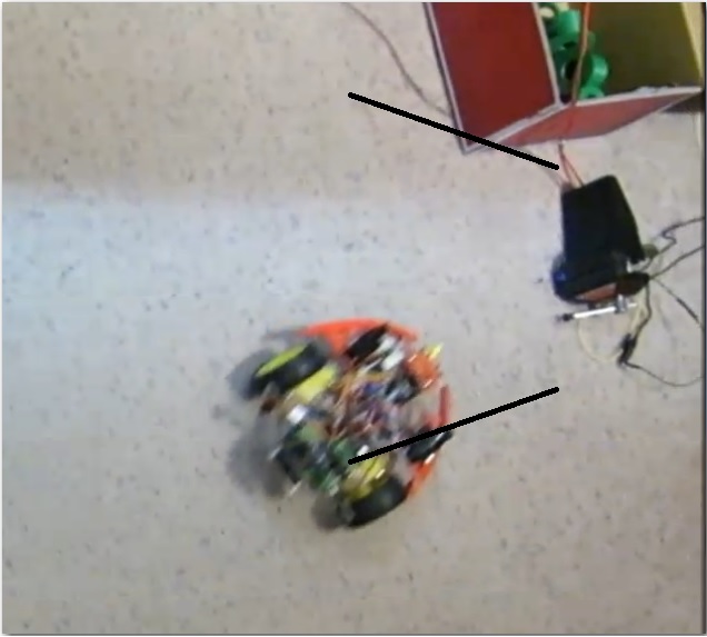
Here’s a short video clip of a few simulated engagement/disengagement cycles


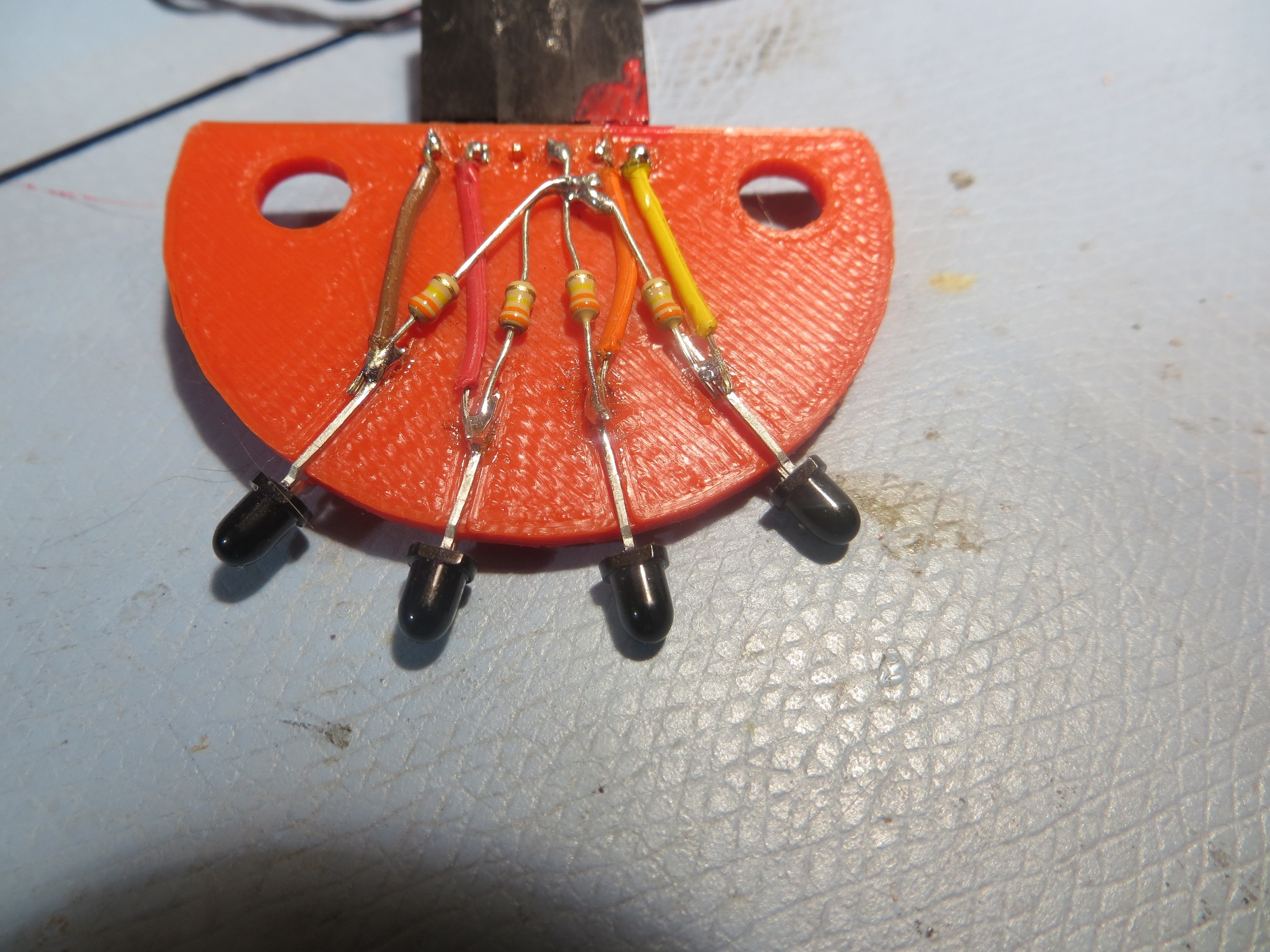
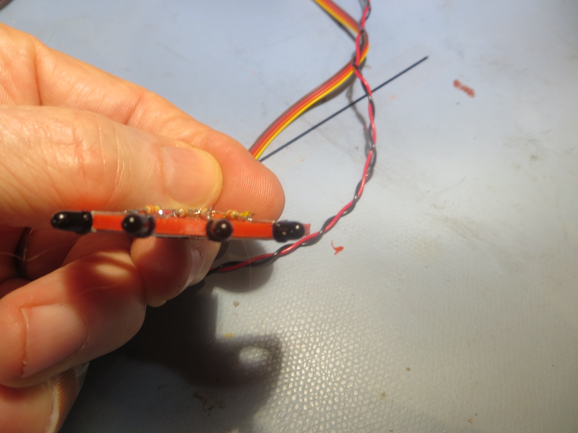
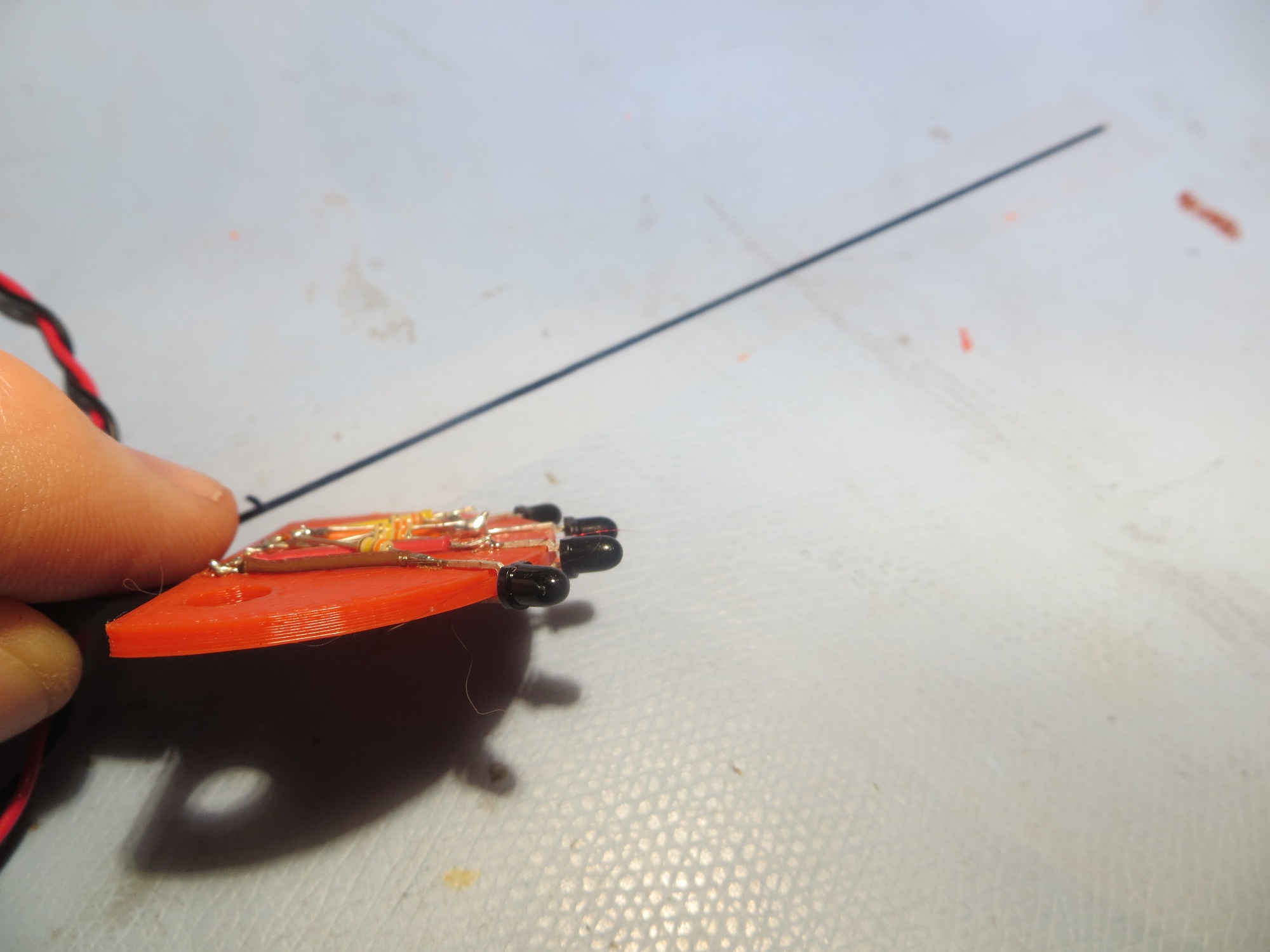
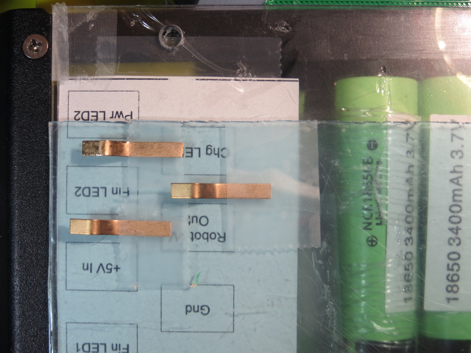
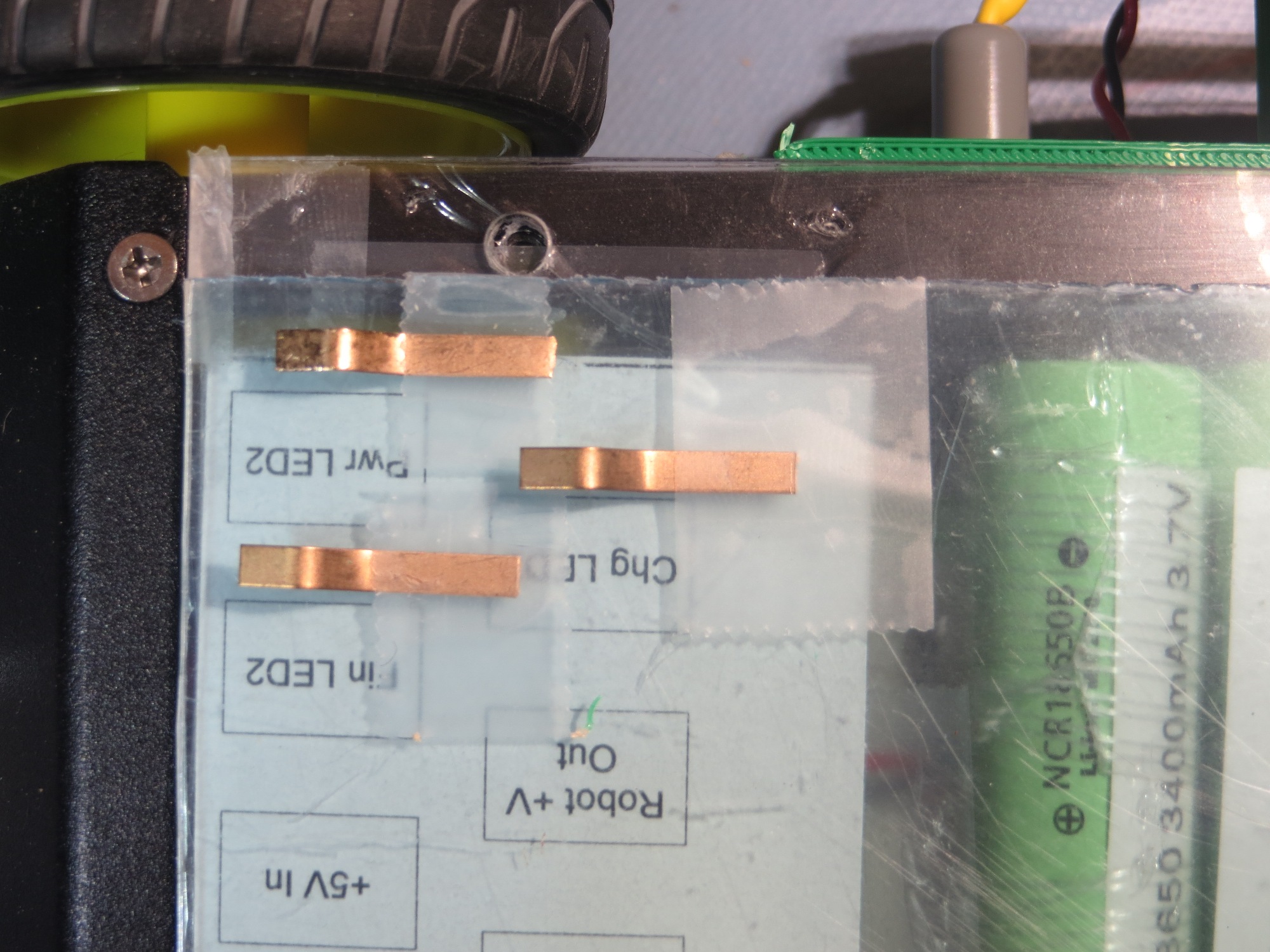
The next step was to fabricate the robot-bottom contacts from copper tape and wire them to the charging module.  Here are some photos of the finished product.

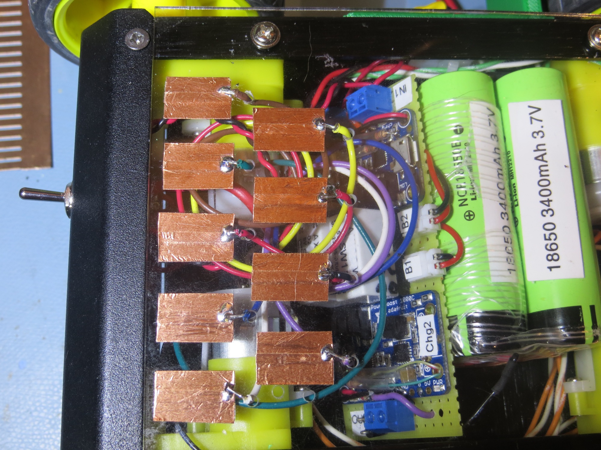
Interface contacts fabricated and wired to charging module

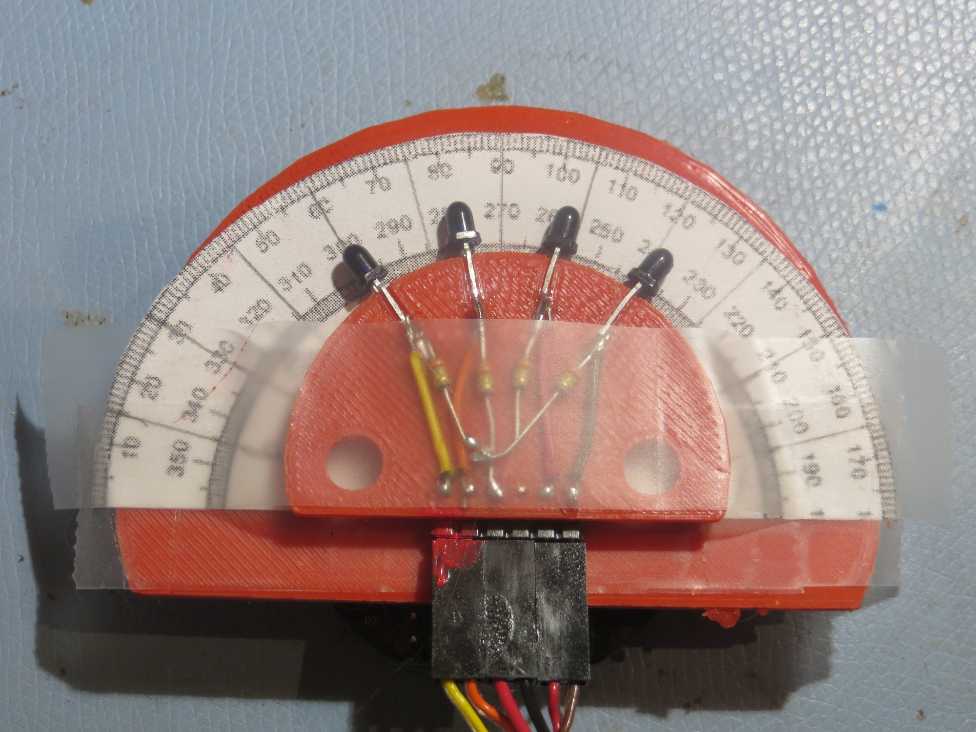
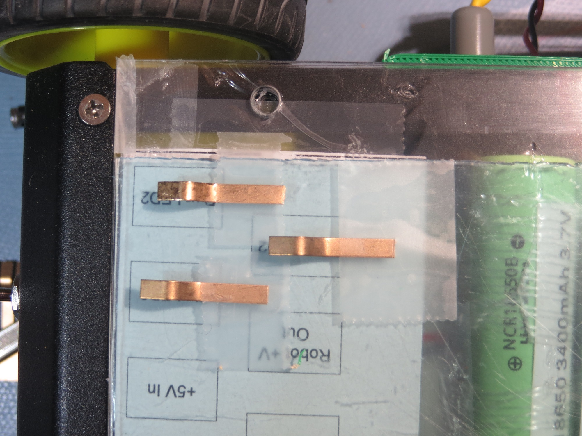
When I looked at the completed module, I recognized that I still had two issues remaining.  The first and more important one is that I needed a strip of insulation to having the sliding contacts short to ground  or each other as they moved across it on their way to their final destination. The second one was that it would be nice to label the contacts so that I wouldn’t have to trust my very untrustworthy memory.  As I thought about this, it occurred to me that I could kill two birds with one stone by placing a label strip on the chassis, as shown below – cool huh!

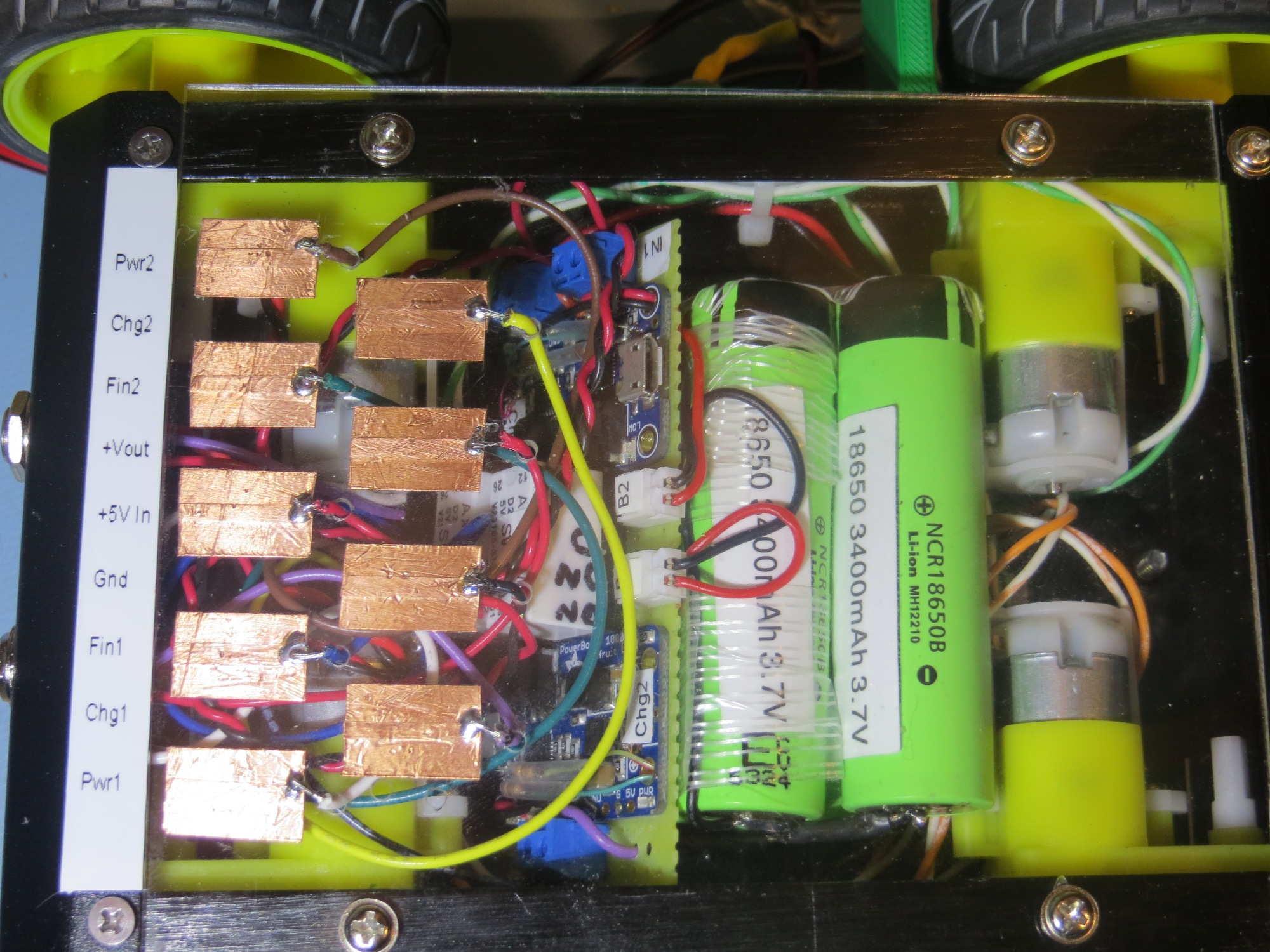
Added labelling to contact array. This was a ‘two-fer’ as it also prevents contact shorting to chassis

Frank


Wall-E2 Charging Station Design, Part IV

Posted 10 December 2016

Well, two important steps occurred today in my plan to take over the world (well, maybe just make Wall-E2 more human-independent). The first was the arrival of my Panasonic 18650 batteries, and the second was the successful trial of my first stab at a charging platform.

The ‘platform’ part of the charging system (the blue piece in the image below) is the part that captures and positions the robot accurately enough to connect to charging power, via contact strips on the bottom of the robot and spring-loaded contacts on the platform.

1/2-scale concept model for the Wall-E2 charging station.  The blue part is the ‘charging platform’

So today I printed out a full-scale platform.  This was pretty amazing by itself, as it took up nearly the entire build area, and took about 4 hours to print.  Fortunately I had recently upgraded my build platform with a PEI surface and also re-leveled it, so the printer was up to the task. It did take me a while to get the darned thing OFF the build surface, as it was  very well adhered to the base 😉

Robot’s eye view of the charging platform

Overall view of the lead-in rails and the charging platform

Closeup of the charging platform piece. Note the beveled section at the entry end

To test the combination of the lead-in rails and the charging platform, I double-sided taped  the platform in what I hoped was the best position/orientation, and ran some more tests with the robot, as shown in the following video clip.

This last series of tests, in conjunction with my earlier work on IR following,  was quite rewarding for me, as I now had incontrovertible proof that the lead-in rail/charging platform idea would really work.  It might not be ‘optimum’, but I was now sure I could get the robot to track an IR beam accurately enough to get captured by the lead-in rails, and the platform would position the robot accurately enough to make the charging connections – yay!!!

Now I have to start serious work on the other end – the actual charging and battery circuitry.  With the arrival of my Panasonic 18650 cells, I now have all the required parts – I just have to put them all together, make it all work, and somehow shoehorn the entire mess into the robot!

Stay tuned,

Frank


Wall-E2 Charging Station Design, Part III

Posted 12/05/16

I’ve been making some progress with the planned charging station lead-in rails.  These rails (shown in yellow in the image below) are intended to guide the robot into the charging station,  lining it up  properly  with the charging station so the contacts on the bottom of the robot will properly mate with the corresponding contacts on the top of the charging station platform.

1/2-scale robot chassis on the 1/2-scale charging station model

1/2-scale robot chassis on the 1/2-scale charging station model

These rails are too big to print in one piece on my PowerSpec PRO 3D printer, so I had to devise a way to print them in sections, which could then be plugged together to form the complete rail.  To do this, I designed a  coupling geometry consisting of a ‘puzzle-piece’ connector and a slide-fit arrangement, as shown below:

Lead-in rail angle coupling design

Lead-in rail angle coupling design

Lead-in rail straight coupling design

Lead-in rail straight coupling design

After going through several iterations ‘on paper’, I printed out a 1/2 scale model to verify that I could indeed connect the pieces to make a whole lead-in rail, as shown below:

Half-size capture basket rail

Half-size capture basket rail

Half- and Full-size capture basket rails

Half- and Full-size capture basket rails

Full-size capture basket rails

Full-size capture basket rails

Now that I had the capture rails fabricated, it was time to find out whether or not the capture system would actually work.  I used double-sided tape to affix the two rails to one section of the heavy plastic desk-chair runner system in my lab/office, at the proper spacing to just pass the robot, assuming it was properly aligned with the capture gap, and then ran some tests, as shown in the attached video clip.

In the video clip, the first two trials were conducted with the ‘stock’ wheel guards with right-angle corners, and the remaining ones were conducted after filing a small bevel into the front corners to (hopefully) alleviate the sticking problem


Front wheel guard with filed bevel on outboard corner

After seeing that the filed bevel seemed to improve performance, I decided I would go ahead and redo the wheel guards to provide a more pronounced bevel.  Thanks to TinkerCad and my trusty 3D printer, this was a piece of cake.

Redesigned wheelguard to incorporate bevel on outboard corner

After changing out the wheel guards, I ran some more tests with my taped-down capture basket,  but soon discovered yet another ‘capture failure mode’, as shown in the following image.

Robot stuck in capture basket

As you can see in the image, the rear part of the front wheel guard and the front part of the opposite wheel guard is just the right shape and spacing to form a stable lockup configuration.  To address this little problem, I decided to remove the rear portion of the front wheel guard on each side, but left the two rear wheel guards intact.  Then I ran some more capture basket tests, with very encouraging results.


So, at this point I’m pretty happy with the capture basket lead-in rail design (3 failures in 14 tries), and with the robot wheel guards.  Next, I’ll need to fabricate a full-scale charging platform for the robot to stop on, and also work on the new charging/battery setup in the robot itself.  Stay tuned!

Frank


Wall-E2 Charging Station Design, Part II

Posted 21 November 2016

Currently Wall-E2 is powered by a 2-cell LIPO 2000maH, 20C RC battery as    shown below.

Current Wall-E2 battery pack

Current Wall-E2 battery pack

The charger I use is a X-Charger C6 model, which works great,  except it has to be manually connected to the main T-connector, and manually started using front-panel pushbuttons.

LIPO Battery Charger

LIPO Battery Charger

For my planned charging station, I need a charger that can be automatically activated, either by simply driving Wall-E2 up onto the charging platform, or by computer control (Arduino or some such controller).  After Googling around for a while, I thought I was pretty much going to be forced to roll my own high-rate 2-cell charger, as I couldn’t find anything like the XCharger above but with a computer control option.  Then, in an uncommon burst of inspiration, I realized I could use the balance connectors associated with all these high-rate packs to charge both cells in parallel, using any one of the many popular computer-controllable single-cell LiOn/LiPO chargers, like this one from Adafruit, shown below:

Adafruit PowerBoost 1000 LiOn/LiPo charger

Adafruit PowerBoost 1000 LiOn/LiPo charger

And some LiPo batteries to go along with it, like these

Adafruit 3.7V 2500mAh LiPo battery

Adafruit 3.7V 2500mAh LiPo battery

After thinking about this for a while, it now occurs to me that I might wind up with something very close to the setup I had in my original Wall-E wall following robot, with two 3.7V single-cell  batteries and two  charging modules on the robot, with a DPDT relay to switch the cells from series connection  (to run the robot) and independent (for charging).

The issue is how to charge the battery pack; I can charge a 2-cell pack with my XCharger, but that requires manual interaction each time, and the XCharger is physically large.  Physical size isn’t a huge problem for the fixed-position charging station, but the manual interaction issue is a deal-breaker.  There are some designs for DIY multiple-cell LiPo chargers out there, but I don’t want my wall-following robot project  to metastasize into a LiPo charger design project (I already have enough alligators in this swamp – no need to add more!). So, since really nice single-cell charging modules are already available, why not use them?  As a bonus, the chargers can be mounted on the robot within easy reach of the standard 2-pin JST-PH connectors, so all I need on the charging station side is +5V DC power, which I can apply through the planned spring-loaded connectors on the bottom of the robot.  As an added bonus, I  might be able to fit the entire assembly into the bottom cavity along with the motors – this would free up lots of space and dramatically simplify the currently somewhat messy wiring layout

The following images shows the Wall-E wiring diagram from about 18 months ago


Wall-E charging setup from early 2015

Wall-E charging setup from early 2015

Original Wall-E battery charger and relay installation. Relay is at bottom right corner of the photo

Original Wall-E battery charger and relay installation. Relay is at bottom right corner of the photo

The only difference between the above setup and my planned one for Wall-E2 is the batteries themselves are 2500mAh instead of 2000, and the charging modules are a heavier-duty type.

Stay tuned!

Frank


Wall-E2 Charging Station Design, Part I

Posted  20 Nov 2016

As the reader might recall, my grand plan for forcing  the entire universe to kneel to my all-powerful  Wall-E2 robot  (OK, so that is a slight exaggeration – my real plan  is to subject our two cats to the depredations of an always-charged wall-following robot).  Wall-E2 has been wall-following for a while now, but I hadn’t been able to come up with a good idea for how to get it to locate and connect to a  charging station.  This all changed when I happened upon the OSEPP IR-follower module at MicroCenter, which resulted (eventually) in my 4-detector adaption of that concept.  After some additional work, I arrived at a reasonably effective PID-based IR-homing algorithm for Wall-E2.  So, now it is time to start working on the design and fabrication of a charging station.

Charging Station Concept:

The concept for Wall-E2’s charging station is that an IR emitter will be mounted in such a way as to lure Wall-E2 into a ‘capture basket’ formed by a set of slanted guide rails.  Once in the basket, Wall-E2 will be forced up a ramp to a pedestal that will further guide the robot to a point where contacts on Wall-E2’s underside mate with contacts on the pedestal.  Once the contacts mate, the motors  will shut down and charging will commence. When charging is complete, Wall-E2 will back down off the pedestal and out of the capture basket, and continue its normal wall-following/cat terrorizing operations.

Using TinkerCad, which just has to be the greatest, most user-friendly 3D design platform known man, I whipped up a half-scale model of the charging station, and of the Wall-E2 robot chassis, as shown in the following screenshots.

1/2-scale concept model for the Wall-E2 charging station

1/2-scale concept model for the Wall-E2 charging station

1/2-scale model of the Wall-E2 4WD robot chassis

1/2-scale model of the Wall-E2 4WD robot chassis

1/2-scale robot chassis on the 1/2-scale charging station model

1/2-scale robot chassis on the 1/2-scale charging station model

Having the ability to put a 1/2 scale 3D model of the robot chassis on my newly-designed 1/2 scale model of the charging station is that I can immediately check for dimensional goofs (not that I  ever make that sort of mistake!).  Even more cool, I can easily examine internal structural issues by temporarily converting the entire robot chassis into a ‘hole’, making it transparent. This capability  immediately paid off, as I was able to identify an interference condition between the station pedestal and the robot’s wheels.  As shown in the following screenshot, the inside of the wheels have an interference fit with the sides of the pedestal (the dark areas indicated by the arrows on the bottom inside portion of the robot’s front/rear wheels).

Closeup of Wall-E2 on the charging station, with the chassis model made temporarily transparent. Note the interference fit between the robot's wheels and the pedestal (arrows)

Closeup of Wall-E2 on the charging station, with the chassis model made temporarily transparent. Note the interference fit between the robot’s wheels and the pedestal (arrows)

This sort of problem is trivial to fix at this stage, since nothing has been fabricated.  Gotta love that 3D modeling stuff! ;-).

When I created the charging station conceptual design in TinkerCad, I sort of eyeballed the angle of the ‘capture basket’ sides with respect to the station centerline at 20 º.  As a sanity-check, I measured (in TinkerCad, it is usually convenient to simply construct a measuring stick from a box object) the opening in the ‘capture basket’ at about 158mm, or about  1.8 robot-widths.  Then, going back to the videos I made during the PID tuning effort, I was able to superimpose the capture basket rails onto the last few frames of the video to see how well the capture basket dimensions fit with the observed homing behavior.

First, I captured a representative frame from my last/best ‘straight-in’ approach, and used Paint to add some lines to represent the capture basket lead-in rails.  For this purpose, I measured  the width  of the robot in pixels (about 250 px), and used 1.5x instead of the measured 1.8x to compensate for the wheel guards on the actual robot.  I called this measurement ‘Rwp’. Then I drew a 40deg capture basket with two lines starting about 0.5Rwp above and below the IR emitter location.  As can be seen in the following image, the robot will indeed be captured within this capture window, at least for the ‘straight-in’ homing case.

Frame from straight-in homing video, with simulated capture basket lines

Frame from straight-in homing video, with simulated capture basket lines

Then I did the same thing for a frame from my ‘Side Capture’ video, as shown below.  For this frame, Rwp is about 200, so the capture basket lines were adjusted accordingly.

Frame from side capture homing video, with simulated capture basket lines

Frame from side capture homing video, with simulated capture basket lines

As can be seen in the image, the robot would have hit the right side capture basket rail.  So, something will have to be done to limit the emitter beam width so that the robot can’t detect the beam unless it is more aligned with the charging station centerline.

Stay tuned!

Frank


IR Light Follower for Wall-E2, Part X. More PID Tuning

Posted 19 November 2016

Well, as usual, things aren’t quite as simple as they seem, and the ’10 minutes, tops’ rule still applies (whenever someone says ’10 minutes, tops’, they are lying by  at least one order of magnitude!).  But, on the bright side, I really do understand PID control systems a lot better now (a low bar, as just the other day couldn’t remember what the ‘P’ in ‘PID’ stood for!), and I now think that WallE (and/or WallE2) has  a pretty reasonable chance of homing in on an IR beacon with sufficient accuracy to be captured by a charging station setup.

In my last post on PID tuning, I had assumed that the PID compute engine normalized the tuning constants before doing the computation, and I decided I needed to check that assumption before continuing.  When I looked into the actual code in the Arduino PID library, I found that this was  not true – the PID compute engine does not normalize.  It simply computes the PID expression:

output = kp * error + ITerm- kd * dInput;

where ITerm is  ITerm+= (ki * error)

However, what this means is that my previous attempts to simplify the tuning problem by eliminating the I and D terms and just tuning the P term was doomed to failure – there was no way ‘do just P’ because the physical dynamics are too complex.  The response curves of the IR detectors (shown below),

4-detector heading test results

4-detector heading test results

combined with the physical dynamics of the robot itself, require more than just a proportional response to the error (the difference between the sums of the two left and two right detector readings)   term.  Ken suggested I could do this by using a pulse train (similar to PWM) for the motor drive signal, but I think that is equivalent to adding some ‘D’ to the PID tuning parameters.

In addition to the physical dynamics issues, there is also the problem of the detector response versus distance.  At maximum detection range, all detector readings are near 1000, so the error term is very small, on the order of 10-50.  However, as the robot gets closer to the emitter, that error term rapidly gets much larger, on the order of 500-900.  This means that the PID tuning parameters appropriate for the ‘far’ case will be wildly inappropriate for the near case (another consequence of not normalizing the PID values internally).

In any case, after a  loonnnggggg series of floor field tests, I think I have arrived at a reasonably effective homing algorithm.  Instead of trying to modify the PID tuning parameters as the robot approaches the emitter, I found it more effective to keep the PID tuning parameters constant, and instead scale the  PID input (error) signal in three steps; 1 (no scaling) for error term values below 200, 0.2 (divide by 5) for values between 200 & 500, and 0.1 (divide by 10) for values above 500.  A representative set of data and some videos are shown below.  The last video shows a ‘side capture’ scenario, where the robot approaches at right angles to the IR beam and successfully captures the beam and homes in on the emitter.

Typical run with 1/5/10x scaling as emitter is approaced

Typical run with 1/5/10x scaling as emitter is approached.  Scaling term is shown here at 100x for clarity

Side capture scenario. Scaling term is shown 100x for clarity

Side capture scenario. Scaling term is shown 100x for clarity


So, at this point I’m convinced that the PID/input scaling arrangement will work, and that I can get WallE2 to home in on an IR beacon.  The next challenge will be to integrate the IR homing function with the normal wall-following function, and to design/fabricate the charging station itself.  Stay tuned! ;-).

Frank


IR Light Follower for Wall-E2, Part IX – PID Tuning

Posted 16 November 2016

In my last post on this subject, I described by attempt to add PID control functionality to WallE’s IR light-following algorithm, and this is now looking pretty promising.  As an added bonus, I managed to suck my stepson Ken Frank, who graduated from Cornell with a MS in control theory, into helping me tune the PID controller. His first comment (well, the first comment after the obligatory “what have you gotten me into now, Ollie!”) was something like “you are over-controlling – you should simplify the problem and start with just ‘P’ – no ‘I’ or ‘D’. Then add P/I as necessary after getting the P value right.  Wish I had thought of that! ;-).

Anyway, I revised the code to do just that – with PID tuning parameters of 4,0,0 for both the far away and near cases, and re-ran my ‘floor range’ field test, as shown in the following video clip and plots.

Left/Right Differential (input to PID engine) and Output

Left/Right Differential (input to PID engine) and Output

All data from the run

All data from the run

More to follow…


After taking the above video and data, it occurred to me that it was possible (although not very probable, IMHO), that the PID engine might not normalize the tuning parameters before computing the new output.  So, I ran two more tests – one with a PID of 1,0,0, and another with a PID of 10,0,0.  These tests, along with the ones for 4,0,0, should provide some insight into that question.  As can be seen from the plots, the tracking behavior for all three PID = X,0,0 conditions are pretty similar.  I also included a video clip of the PID = 1,0,0 condition.


161116_floorfieldtest15data 161116_floorfieldtest16data


More to follow

Frank


IR Light Follower for Wall-E2, Part VIII

Posted 13 November 2016

After reviewing the benchtop field test results, I decided to try implementing a PID (Proportional/Integral/Derivative) controller for WallE.  There is a quite nice PID library in the Arduino eco-system, thanks to Brett Beauregard (br3ttb@gmail.com), and  I already had it installed on my system from a previous project.  Getting it implemented for my project  wasn’t too much trouble, but of course  the issue with PID controllers is getting it ‘tuned’ (i.e. finding the values for P, I, & D) for the particular physical setup.

For my 4-detector system, I used the difference between the sum of the two left detector values  and the sum of the two right detector values as the input to the PID controller, and chose a setpoint of zero – i.e. the idea was to drive the difference in the detector sums to zero, which  should mean that the robot is pointed directly at the IR source.  The output from the controller was used in a differential fashion to drive the motors; the output was fed directly to the right motor driver as a 0-255 PWM value, and the left motor drive value was 255-Output.

The first  step was to set the PID values appropriately, and I had absolutely no idea how to do that –  so I just started with  the default values of 2, 5, and 1 for the P, I, and D values respectively, and DIRECT for the sense indicator.  Then I ran some tests on my 24″ benchtop range to see what happened.  Of course the first thing that happened is that WallE immediately departed from the plan and dove off the benchtop (I caught it before it hit the ground).  This was fixed by changing the PID output sense from ‘DIRECT’ to ‘REVERSE’, and I started getting some successful runs.

The next step was to make some more realistic homing tests, and for this I moved the IR emitter from my benchtop down to the floor at one end of my bench, and started WallE from the other end – about 1.5 m away.  I made a number of runs, changing the PID tuning parameters to try and find a reasonable arrangement.  After some playing around and some more Googling, I arrived at a tentative arrangement with a dual parameter set – one for small left/right differential excursions, and another for large excursions.  As  the following video shows, WallE successfully homed in on the IR emitter.

I also captured telemetry from the run, and plotted the left/right differential in Excel, as shown below:

Left/Right differential from 13 November floor field test

Left/Right differential from 13 November floor field test

In the above plot, a marked difference can be seen between the differential behavior up to about point 33, and the differential between 33 and the end of the run at about 55 (the data after 55 was captured after I stopped the robot and picked it up, and before I got it shut down). I believe this change is due to my use of two different values for I & D, triggered when the differential became greater than 200 (due to increased received signal strength at the detectors, and possibly due to higher angle deviation as the robot neared the emitter).  More testing will be required to determine the best set of parameters for the 3-wheel WallE robot.

Once I get comfortable with IR homing using WallE, I plan to transition the capability  to WallE2, the 4WD robot.  This will probably require significant re-tuning, as WallE2’s steering dynamics are quite different.

Stay tuned!

Frank


IR Light Follower for Wall-E2, Part VII

Posted 11/12/16

In my last post on this subject, I demonstrated a 4-detector IR-homing setup that I constructed using some nice OSRAM IR phototransistors. The next step is to mount this module on my robot to see how/if it can be used to home in on an IR source.  Rather than try to integrated it onto my already crowded 4WD WallE2 robot, I decided to see if I could resurrect my original 3-wheel WallE robot and use it as a test platform.

As I mentioned previously, I had found that the OSRAM phototransistors   (in stark contrast to the OSEPP 6-detector IR Follower module) were not at all sensitive to my overhead LED lighting, eliminating the need for a sunshade entirely.  This made the mounting chore a  lot easier, and by happy circumstance, the mounting holes in the 4-detector module matched up with the front caster wheel mounting holes on the original robot.  So, mounting turned out to be just a matter of exchanging the original 3x6mm mounting screws with 3x12s and adding 1/8″ standoffs, as shown in the following photos.

Original 3-wheel WallE, with 4-detector module mounted at the front

Original 3-wheel WallE, with 4-detector module mounted at the front

Closeup of the 4-detector module mount

Closeup of the 4-detector module mount

Next, I went back through all my old Arduino code projects and found the latest version of my 3-wheel robot code (I did mention that I  never throw anything away, didn’t I?). Then I  copied the relevant motor management code from this project into the project I had already started for testing the 4-detector module, and ran a couple of benchtop field tests.  For the tests, the robot started out about 75-80cm from the IR emitter, and (after some tweaking of error feedback factors) was able to home in on the emitter, as shown in the video clip below

I ran this test several times, and the robot was able to home in on (and actually strike) the IR emitter.  A representative final position is shown in the following photo

Final position after IR homing run. Note that the IR detector module actually struck (and bent) the IR emitter diode.

Final position after IR homing run. Note that the IR detector module actually struck (and bent) the IR emitter diode.

All in all, I think the ‘benchtop’ field testing was a qualified  success.  I wasn’t particularly ecstatic about the back-and-forth wandering of the robot as it tracked, but it certainly got the job done (or at least I thought it did until I looked at the actual tracking data as shown below).  As the plot below shows, the left/right differential value appears to be growing larger in each cycle, until the robot ran into the IR LED at about point 82.  This may well be due to my artificially limiting the max differential motor speed value (to less than 1/2 max speed) to keep the robot on the bench top, or possibly due to the positive feedback effect of the castering nosewheel.  Remains to be seen.

left/right Differential (Diff) and Left/Right motor speed values vs time for the 12 Nov 2016 Field Test

left/right Differential (Diff) and Left/Right motor speed values vs time for the 12 Nov 2016 Field Test


It remains to be seen whether or not the castering front wheel contributed to the ‘hunting’ behavior, and/or whether a different selection of error feedback factors would do any better.  Suffice it to say, however, that the tests were certainly successful enough to encourage me to continue this line of development.

Next steps might be to set up a longer range field test, and maybe to set up a situation where the robot has to transition from wall following to IR homing behavior.

Stay tuned!

IR Light Follower for Wall-E2, Part VI

Posted 04 November 2016

As I described in my previous post on this subject, the OSEPP IR Follower is a nice module, but its IR detector arrangement seems to be ill-suited for my intended application, which is to implement an IR homing capability to allow my wall-following robot to autonomously home in on a charging station so it can recharge its batteries and (hopefully) wander the house indefinitely (or at least until one of the cats figures out how to kill it!).

As shown in the following detection vs angle plot for the OSEPP module, there is a dead zone of about 20 º between IR detector beam edges.  This dead zone makes it very difficult to determine the proper steering value to feed to the motors for homing, as it is basically impossible to determine which dead zone the IR beacon beam is hitting.

Results from fourth heading tests on bench-top range. For this test, the idea was to determine the approximate beamwidth of each detector

Results from fourth heading tests on bench-top range. For this test, the idea was to determine the approximate beamwidth of each detector

It would be much nicer if the individual IR detector beams overlapped at their respective half-power points, so that dead zones would be completely eliminated.  This requires that the beam centers be spaced at the same value as the half-power beamwidths, i.e. about 15 º.   So, a six-detector array would span 90 º instead of 180 º

Looking over my electronics parts hoard, I see that I have some Oshram SFH309FA-4 phototransistors on hand that should do the trick, and as a bonus, these units have a 24 º half-sense beamwidth instead of 15 º, which means I can do a 72 º span with just four units – yay!!

OSRAM SFH309FA-4 phototransistor specs, page 1

OSRAM SFH309FA-4 phototransistor specs, page 1

OSRAM SFH309FA-4 phototransistor specs, page 2

OSRAM SFH309FA-4 phototransistor specs, page 2

Using the wonderful DipTrace schematic capture package, I whipped up a circuit using 4ea of the above phototransistors, 4ea 1K load resistors, and a 0.1uF noise suppression cap for good measure, as shown below

Wall-E2 IR Follower circuit diagram

Wall-E2 IR Follower circuit diagram

My first try at a module design is shown below.  Because the print time is so short (~9 min) and the cost is so trivial, it’s easier and faster to just take a stab at the design, print it, and then repeat as necessary to optimize the solution.  The down side, if you can call it that, is that it is so easy to make small adjustments to the design that it is hard to stop – there’s always ‘one more small thing’ that can be done to make the product just a little bit better ;-).

First try at a 4-element IR Follower array

First try at a 4-element IR Follower array

Posted 07 November 2016: USA Presidential Election Eve!

After a few more versions, I had one that I liked.  To test the idea, I mounted the new module onto the old ‘sunshade’ just for mechanical stability, and added the 6-pin right-angle header (4 detectors plus pwr & gnd) and one photodetector, as shown here

Trial assembly of 4-detector module

Trial assembly of 4-detector module


This seemed to be OK, so I went ahead and built up the 4-detector module, as shown in the following photos

Bottom side of assembled 4-detector module, showing all 4 detector emitters tied to ground

Bottom side of assembled 4-detector module, showing all 4 detector emitters tied to ground

Top view of completed 4-detector module. Note load resistors are now 330K for better sensitivity

Top view of completed 4-detector module. Note load resistors are now 330K for better sensitivity

Front edge view of completed 4-detector module

Front edge view of completed 4-detector module

Edge view of completed 4-detector module

Edge view of completed 4-detector module

After verifying that the module was indeed operational, I ran a range test at 24″ from the IR LED.  I really didn’t have a good way of attaching a heading circle printout to the new module, so I simply taped the 4-detector module to the top of the OSEPP module’s sunshade as shown. This let me use the same heading circle printout I used before – clever if I do say so myself! ;-).

Completed 4-detector module taped to original OSEPP module to utilize existing heading printout

Completed 4-detector module taped to original OSEPP module to utilize existing heading printout

After getting everything working, and modifying the Arduino program for 4 detectors vice 6, I ran a detector output vs angle test at a range of 24″ from the IR emitter, as shown.

24" test range for the completed 4-detector module

24″ test range for the completed 4-detector module

4-detector heading test results

4-detector heading test results

The results came out better than I could have hoped.  As can be seen from the data and the plot, I’m getting close to the expected 24 º beamwidth, and it is clear that there are no dead zones between detector minimums.  For every angle between 45 º and 130 º there is no ambiguity as to which detector(s) are active, and how to steer to home in on the emitter.

A couple of  side notes:

  • My original design (see above) used 1K load resistors, but I soon found that to be  way too low – the detectors could barely detect the IR emitter from less than 6″ away.  After some empirical testing, I finally settled on 330K as a reasonable compromise that allows decent response from approximately 1m away.
  • I discovered that the OSRAM photodetectors are not at all sensitive to my LED bench lamps, or to my overhead LED track lighting, due to (I believe) the visible light rejection coating on the detector lens assembly.  This means I no longer need the sunshade at all, which should make the physical mounting issue much easier to deal with.

The next step is a big one, and will require a fair amount of work.  I’ll need to physically mount the new module on Wall-E2, wire it into the Mega controller,  and modify the program to exploit the new capability. At the moment, Wall-E2 is a mild state of dis-repair, so this all may take some time.  No worries – I’ve got plenty of that (I hope).