
Posted 11/22/15
At the conclusion of last month’s episode of “Bringing up Baby” (AKA our new 4WD Robot), my grandson and I had gotten it to the point of doing ‘The Robot Jig’ (a test program to show that all the motors ran in the same direction and at the same speed), but without any sensors or navigation capability. After Danny went back home I sorta let the 4WD robot out to pasture while I concentrated on reworking Wall-E to remove all the spinning LIDAR stuff and add acoustic sensors. This effort was pretty successful, so I thought it was now time to add this same capability to the 4WD robot – now christened ‘Wall-E2’.
The plan for adding sensor capability to Wall-E2 was to move the ‘Blue Label’ LIDAR and two acoustic ‘ping’ sensors from Wall-E. This entailed printing up a new LIDAR bracket (not really necessary, but aesthetically pleasing), and redesigned ping sensor brackets (the retainer latches on the old ones were way too fragile). For a while I toyed with the idea of discarding the 4WD robot’s ‘upper deck’, but in the end I decided that giving up all that future expansion real estate was just too stupid for words. However, retaining the second deck brought with it the challenge of managing the inter-deck cabling in a way that allowed the upper deck to be removed for troubleshooting without having to disconnect anything. IOW, I wanted to be able to run everything on the second deck, while the deck was physically off the robot. Eventually I decided on a hybrid approach to the cabling issue; I added a terminal strip to the underside of the deck, and ran +5VDC and GND wires to it from the main terminal strip, with inline disconnects. Then I permanently connected +5 & GND wires to each acoustic sensor, but ran the ping sensor control lines back to the main deck through inline disconnects. The LIDAR cable was run all the way from the LIDAR to the main deck without disconnects, but this was OK because this cable connects to the LIDAR itself via a multipin locking connector. All the cabling runs have enough slack so that the upper deck can be placed on the bench beside the robot without having to disconnect anything – yay! The following photos show the disassembled and assembled states of Wall-E2.
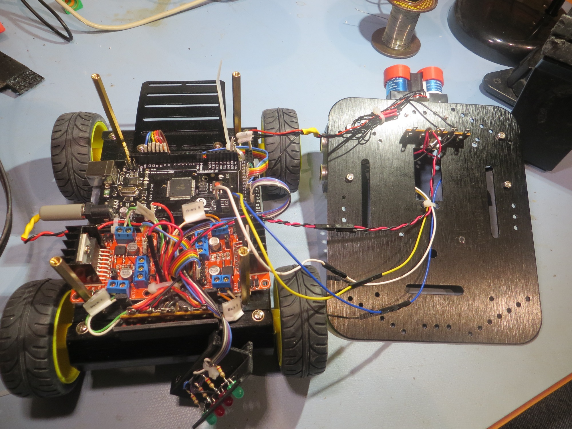
Disassembled robot. Note the inline disconnects on the power/gnd cable and the ping sensor and laser pointer control lines
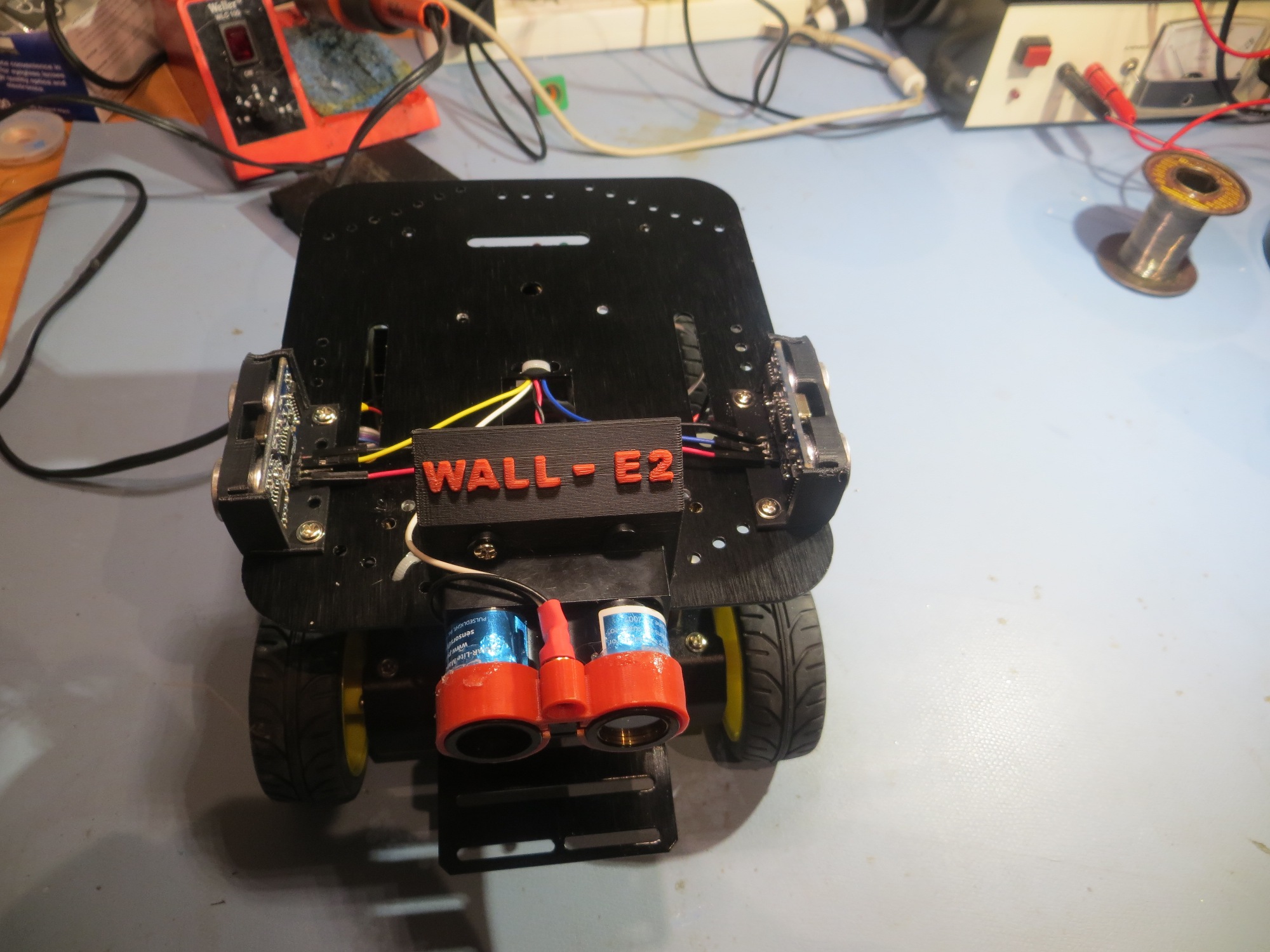
Rear view of the assembled robot
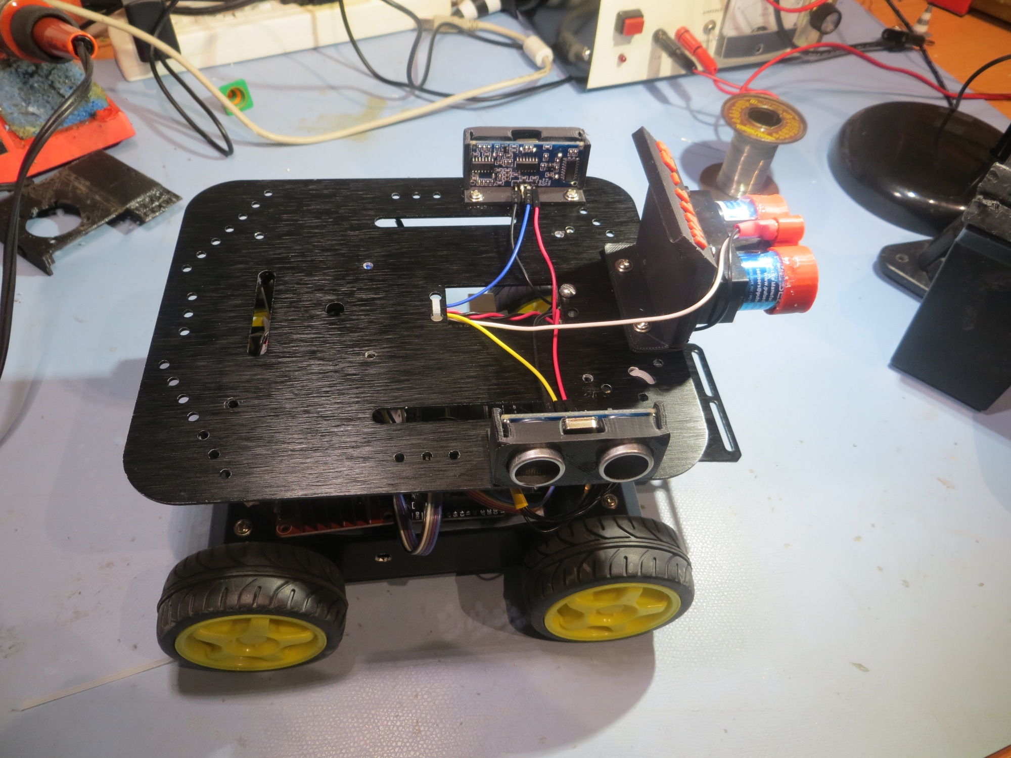
Right side view of the assembled robot
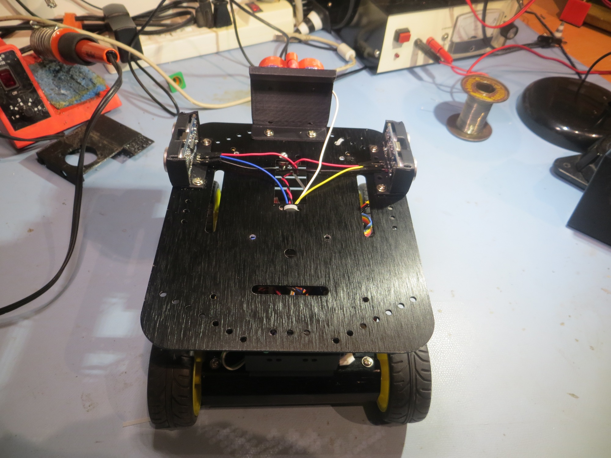
Front view of the assembled robot
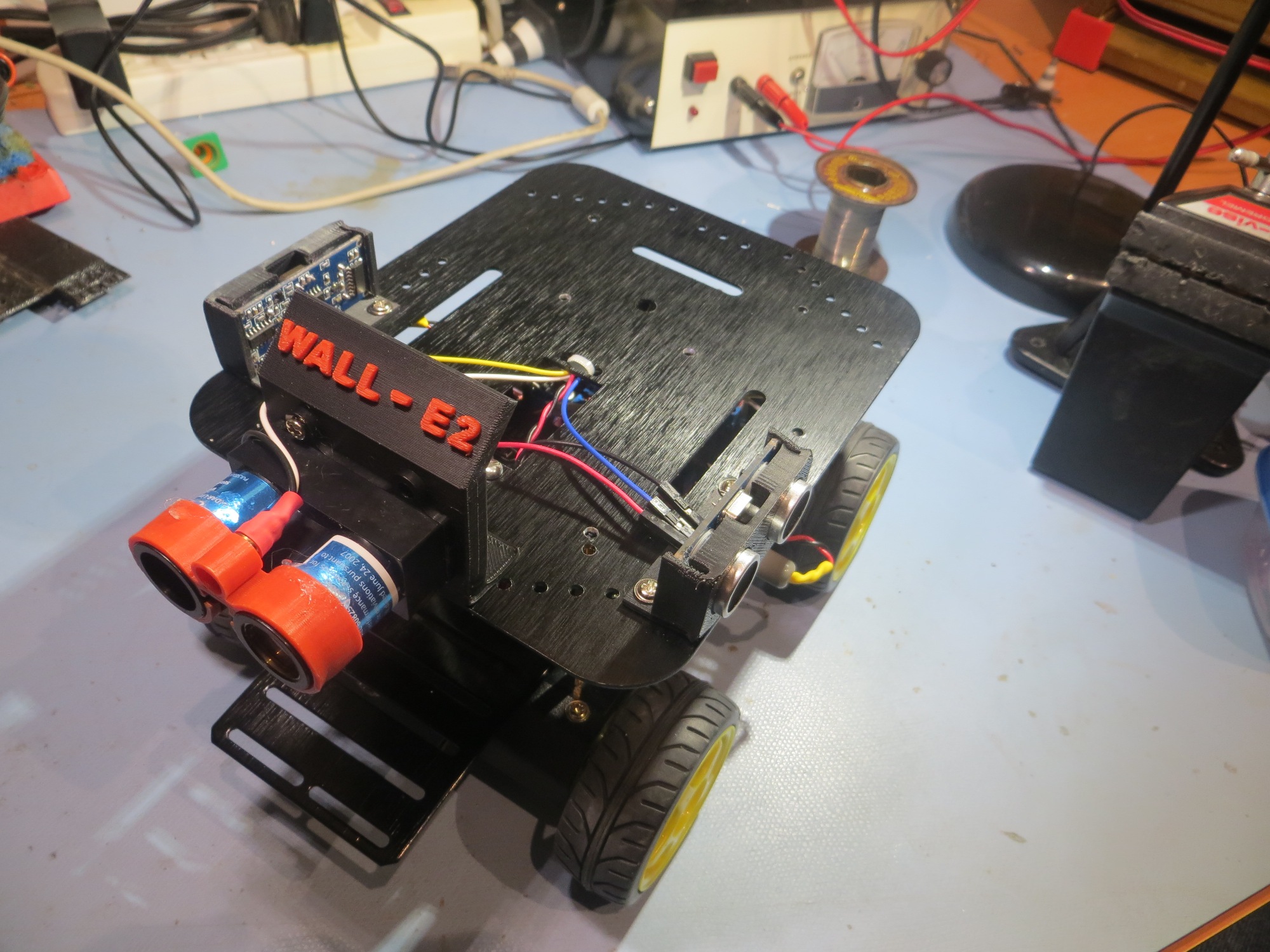
Left front quarter view
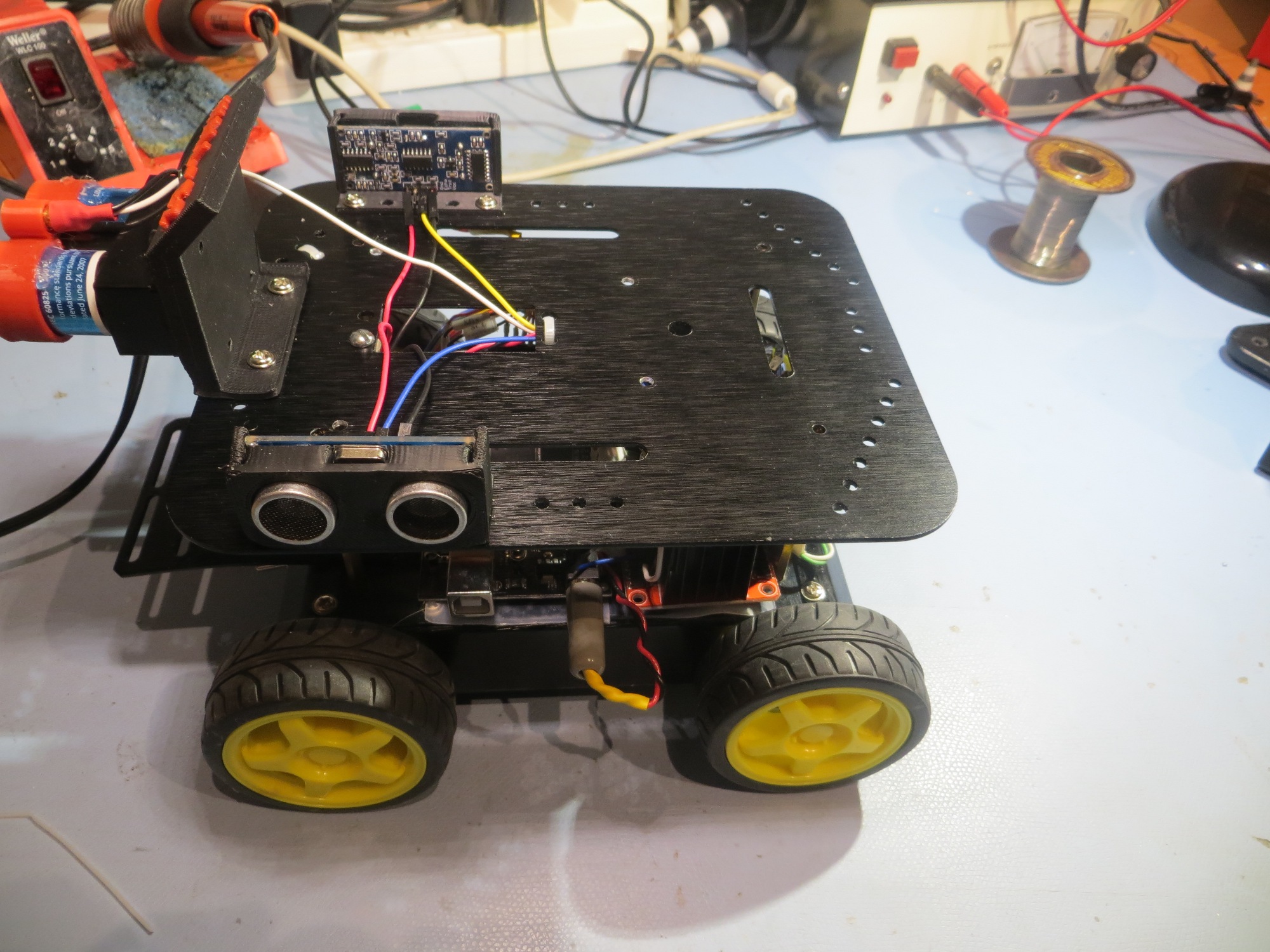
Left side view
So, at the end of this episode, all the mechanical and electrical work has been accomplished, but nothing has been tested yet. It’s late, so I think I’ll wait until I have more than two neurons to rub together to check things over and test things out. I have found over time that late-night testing almost invariably leads to next-day wailing and gnashing of teeth 😉
Stay tuned,
Frank