
Posted 11/21/15
In the process of building up my 4 wheel drive replacement for Wall-E, I ran across a problem that turned out to be a perfect showcase for the power of home 3D printing. The problem was what to do with a terminal strip mounted at the rear of the robot chassis, as shown in the photo below. Interestingly, the terminal strip itself is sort of a story of its own; it is from the bygone era of point-to-point wired electronics, and they aren’t readily available anymore, even though they are perfect for this sort of robotics project. I had this one left over from some 20-year old project, and when I tried to find a source for re-supply, I almost struck out entirely. I finally found a source at Surplus Sales of Nebraska – add this one to your bookmarks!
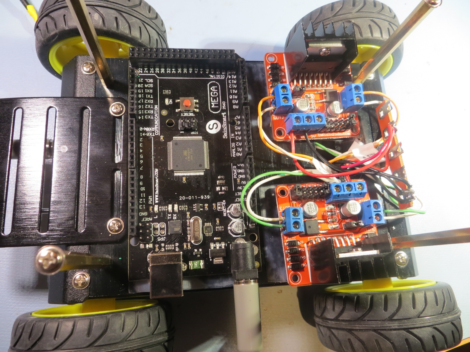
4WD Robot with old-style terminal strip shown at the rear (right side in this photo) of the chassis
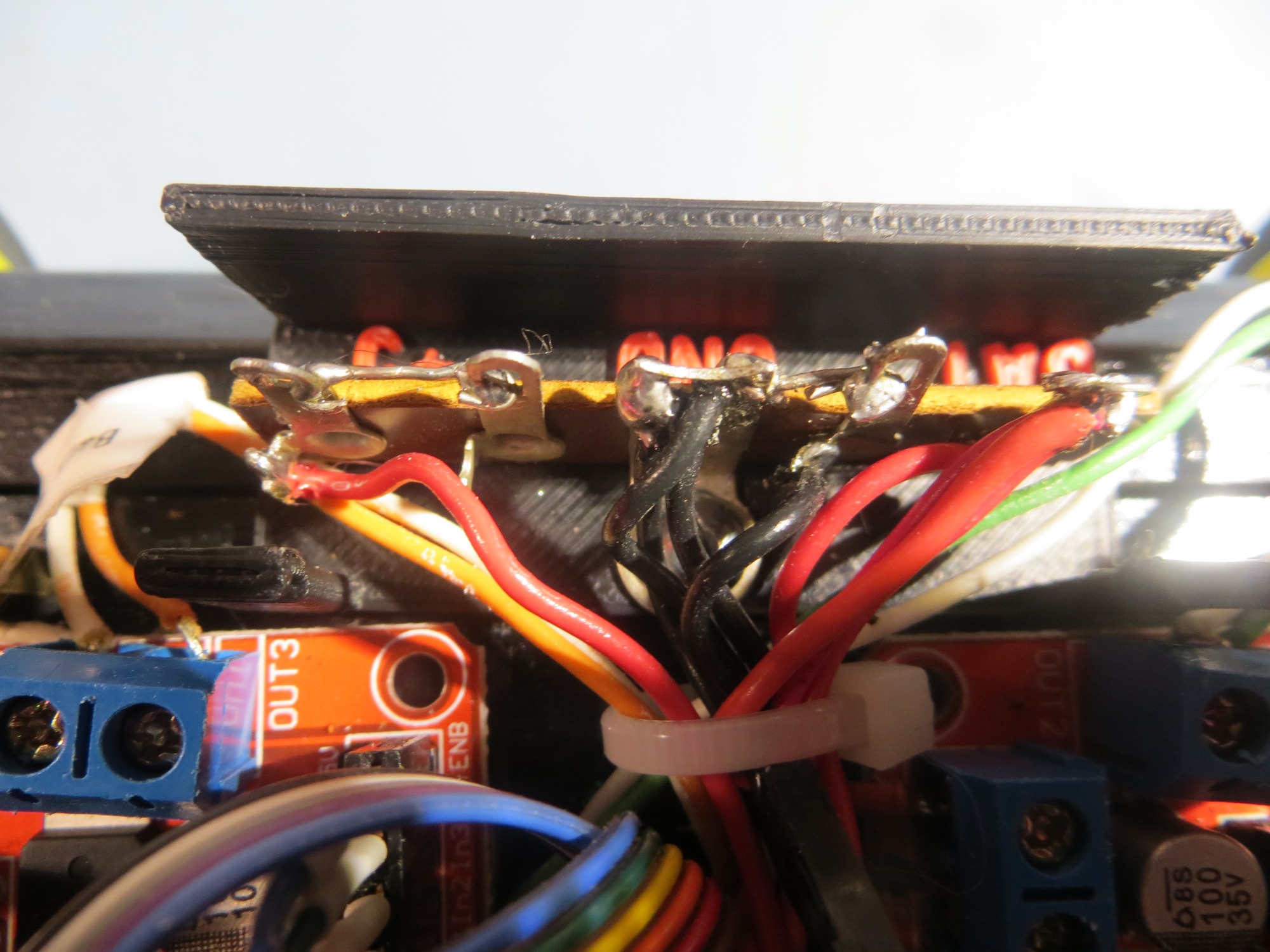
OK, so the problem is – the terminal strip is great for what it is doing, but now I have Vbatt, +5V, and GND all exposed where an errant wire or screwdriver could cause real problems – what to do? Moreover, I needed some way of labeling the strip, because I now had two sets of red wires (one from the battery pack, one from regulated +5), and without some obvious and permanent labeling scheme, I was for sure going to screw this up at some point. Before the recent advent of 3D printing and the ‘maker’ revolution, this would have been a real show-stopper. I could have maybe found a small plastic box that I could cut down or reform somehow, or milled something fancy from a block of Lexan, but the cut-down box wold be inelegant to say the least, and the fancy milled piece of Lexan would be exorbitantly expensive and time-consuming, even assuming that I got it right the first time (unlikely). However, now that I have the super-power of 3D printing at my fingertips, I “don’t need no stinking Lexan!”. All I need is my imagination, TinkerCad, and my PowerSpec 3D Pro dual-extruder printer!
So, using my imagination and TinkerCad, I rapidly sketched out a design for a U-shaped protective shroud for the terminal strip, and printed it out. Once I had it mounted, I realized that I had only done half the job – literally! The U-shaped shroud protected the terminal strip from the front, but not from the top – I needed a lid of some sort to finish the job. Having a lid meant there had to be some way of keeping the lid on, while still being able to easily remove it to make changes to the strip wiring, so I needed some sort of snap-action latching mechanism. This resulted in the design shown in the following photo. The U-shaped shroud is shown in blue, with the lid shown in green. the complementary groves allow the lid to snap onto the trough.
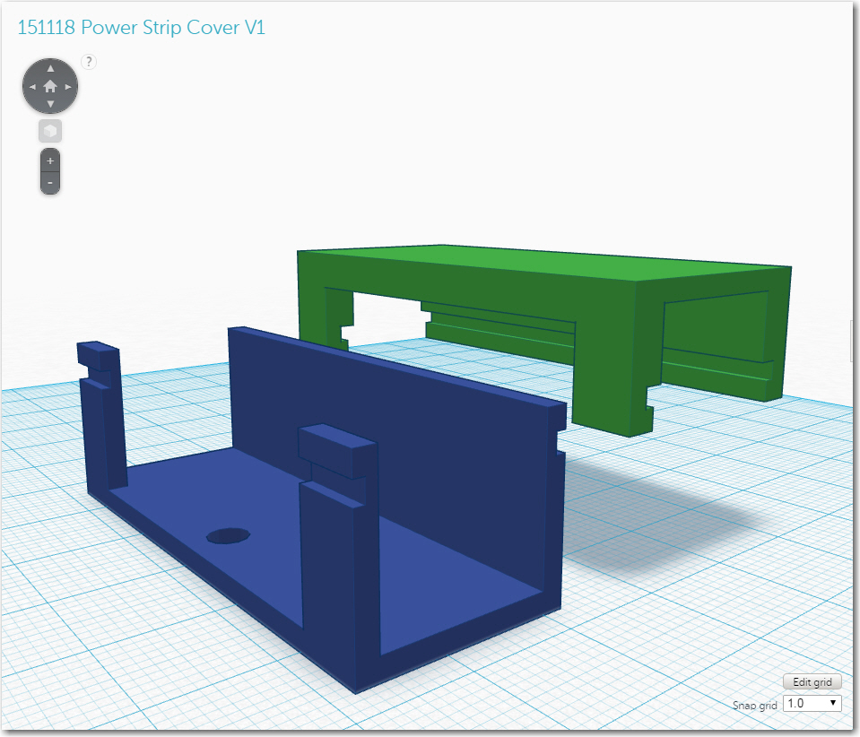
Early version of the power strip cover and lid
In another hour or so, I had both parts printed up and mounted on the robot – and it worked great! However, as often happens when I design and print 3D parts, I immediately saw possibilities for improvements. The first idea was to incorporate the labeling right into the shroud design, literally. I have a dual-extruder printer, so that meant that I could put the ‘Vbat’, ‘GND’ and ‘+5’ labels directly into the material, in a contrasting color – cool! In another hour or so, I had the labels incorporated into the design and another piece printed out, with the result shown below
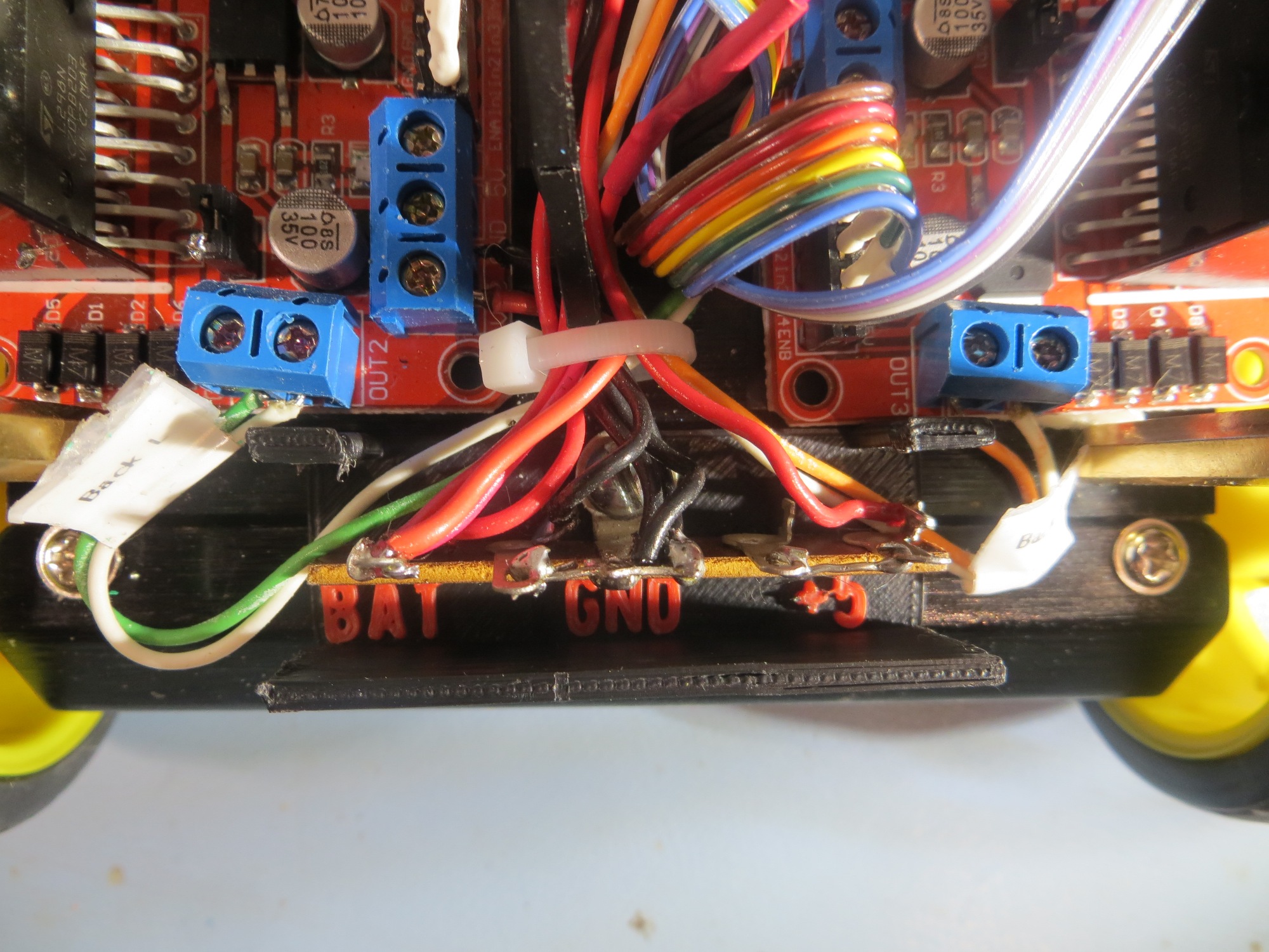
View showing the bottom part of the two-part cover, with integrated terminal labels
Another view of the bottom part of the two-part cover
After admiring my work with the integrated labeling, and the way the lid snapped on and off firmly but easily, I had another cool thought. Wall-E has a set of 4-LED’s mounted at the rear of its chassis, and the software uses these to announce various program states, and I wanted to do the same thing for the new 4WD robot. However, I had not yet figured out where I was going to put them, and it suddenly occurred to me that I could use my new terminal strip cover as the platform for some readout LED’s – cool!
So, in another hour or so I had yet another version designed and printed out and installed on the robot chassis, as shown in the photos below
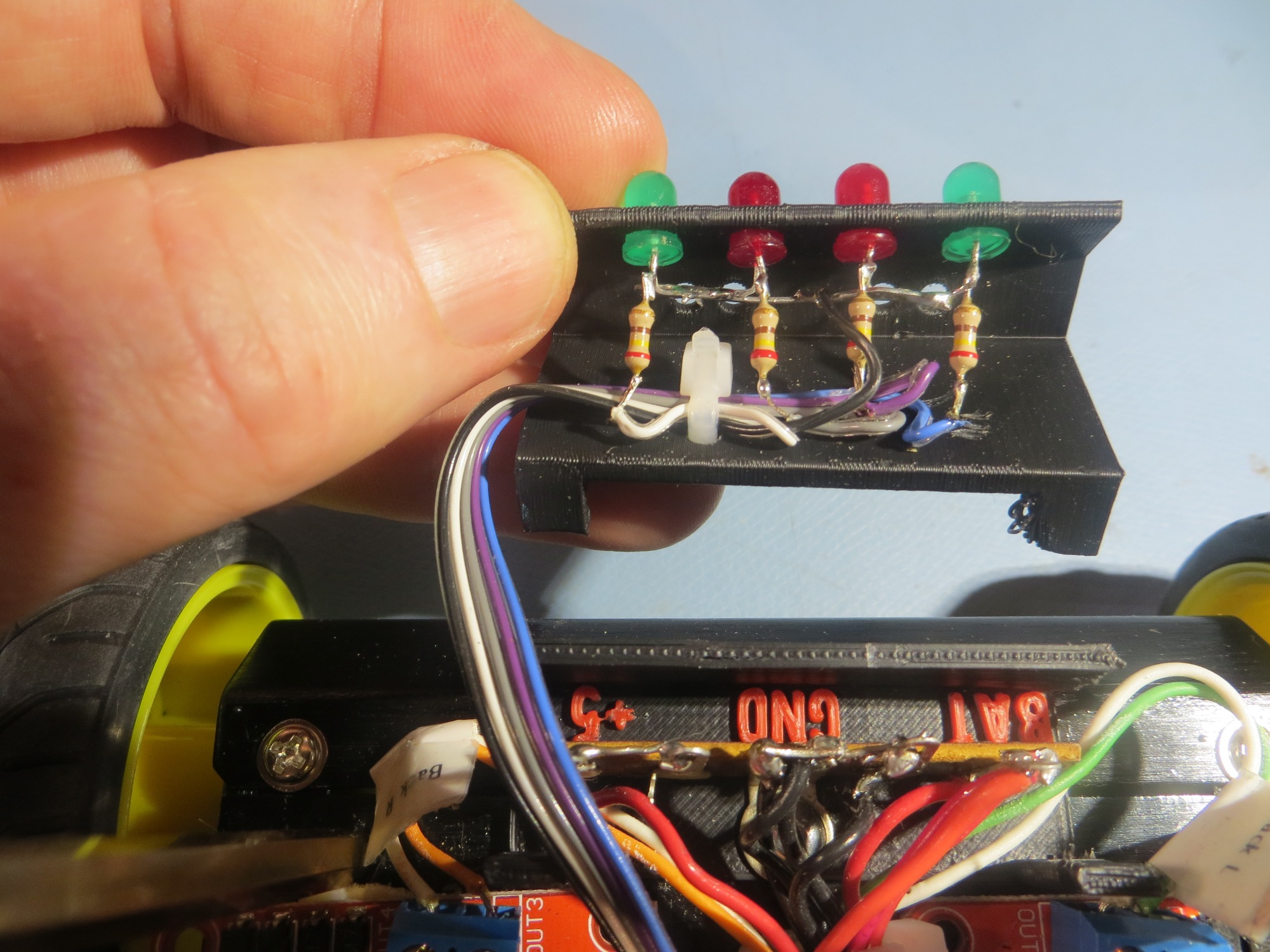
Inside view of the top part of the two-part terminal strip cover, showing the LED array installation
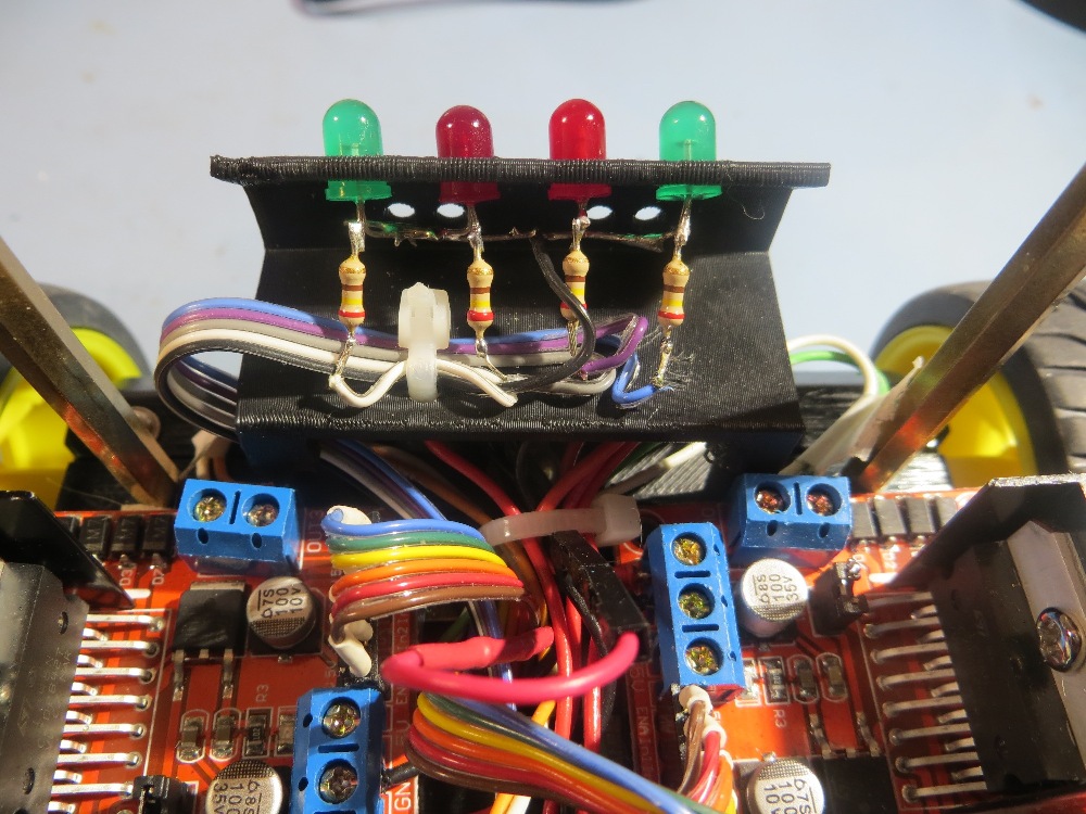
LED Array/Terminal strip cover snapped onto the bottom half
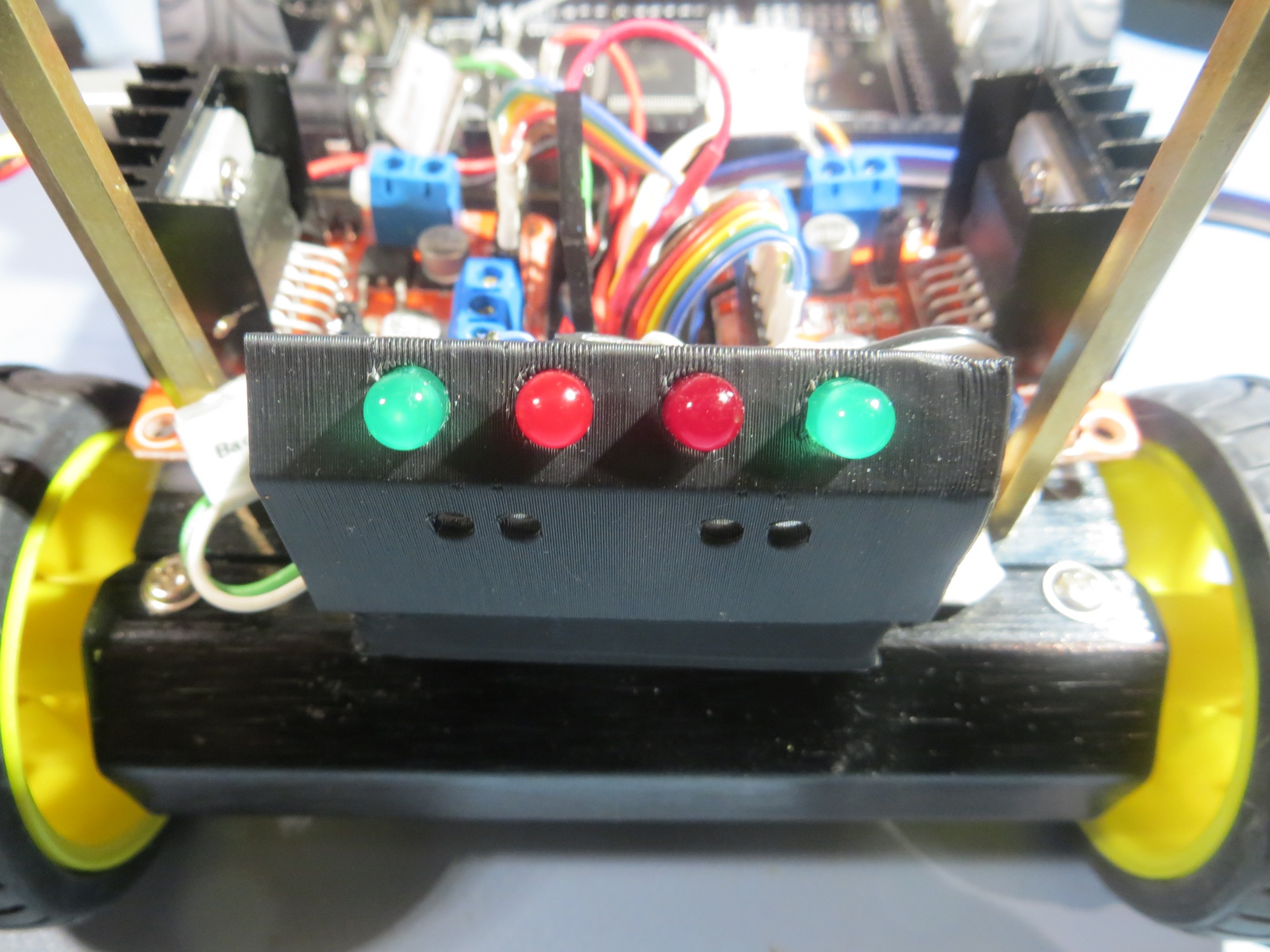
4WD Robot rear view showing the completed cover/LED array bracket
So, in the space of a day or day-and-a-half, I went through a half-dozen or so design iterations, all the way from initial (incomplete) concept and (wrong) implementation, through several completely unforeseeable concept/idea mutations to a ‘final’ (to the extent that anything is final on one of my projects!) implementation that not only solved the original problem (covering the exposed wiring on the terminal strip, but also implemented integrated labeling AND added a completely new and desirable feature – the LED array bracket.
Although this little project is no great shakes in the grand scheme of things, it does serve to illustrate how the combination of essentially infinite computing power, easy-to-use design tools like TinkerCad, and cheap, capable 3D printing tool availability is revolutionizing the hardware/software development world. 40 years ago when I was a young electronics design engineer, there was a huge gap, in money and time, between a working prototype and a finished production design. And, once the production process started, changes rapidly became impossible due to the cost and time penalties. So, everybody tried to ‘get it right’ the first time, and many really cool ideas didn’t get incorporated because they occurred too late in the design-production cycle. Now, many of these constraints no longer apply, at least not for small production volumes; we now able to operate more like the ‘cut-and-try’ generation of the early 20th century. No need to worry too much about which design alternative(s) is/are better when material costs are negligible and design-fabricate-test cycles are shorter than the time required to do a detailed analysis – just build them all and compare them ‘in the flesh’.
Many years ago when I was an active soaring (full-size glider) pilot, I wrote a book (“Cross Country Soaring With Condor”) about the use of a popular soaring simulator as a competition trainer. When it came time to get the book published, I did a lot of research and eventually settled on an outfit called ‘DiggyPOD’, where the ‘POD’ stands for ‘Printing On Demand’. These folks had figured out how to eliminate most of the up-front publishing costs that made traditional book publishing inaccessible to all but established authors and professors with guaranteed markets. Consequently, I was able to get my book published in quantities and at prices that allowed me to make a profit selling into a very restrictive niche market. I think the same sort of thing is now happening in the realm of small volume consumer products. Not only is it now possible to conceive, design, and implement new products at very low cost and without any costly infrastructure, it is also possible to customize existing products in ways that would have been unimaginable 10 years ago. For instance, I recently repaired a friend’s bicycle accessory. This is something that would have been impossible before. I think this ‘maker’ revolution is going to change our world in ways we can’t even begin to imagine!
Stay tuned,
Frank