Posted 10/13/15
After getting the battery pack and charger module assembled and working properly, it was time to integrate it into the 4WD chassis, and add the motor drivers and navigation controller subsystems. The battery pack/charger module was constructed in a way that would allow it to be mounted in the motor bay with the motors, giving it some protection and getting it out of the way of the rest of the robot. The DFRobotics 4WD kit comes complete with a power plug and SPDT power switch, and these were used for charging and main robot power switching, respectively.
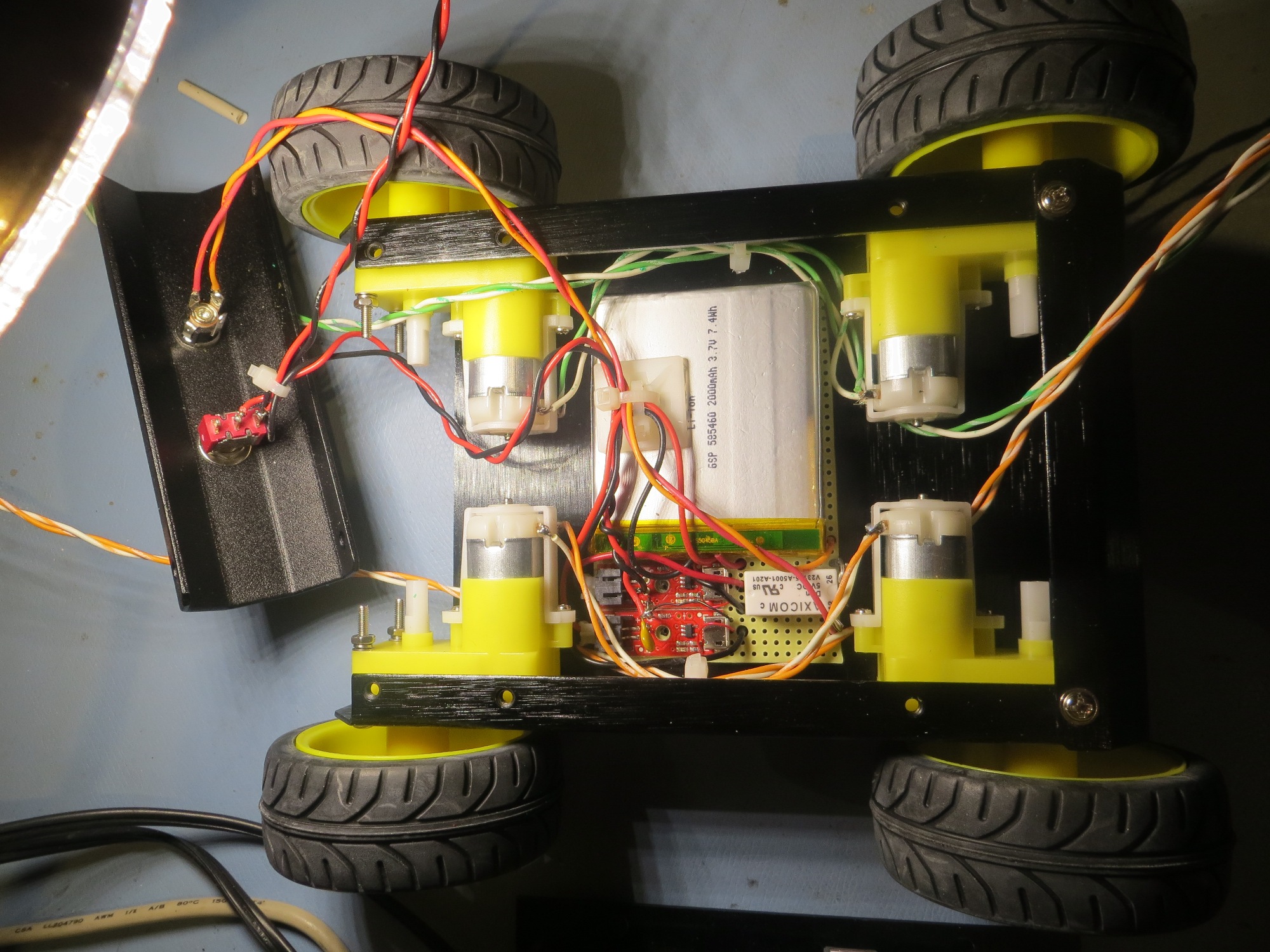
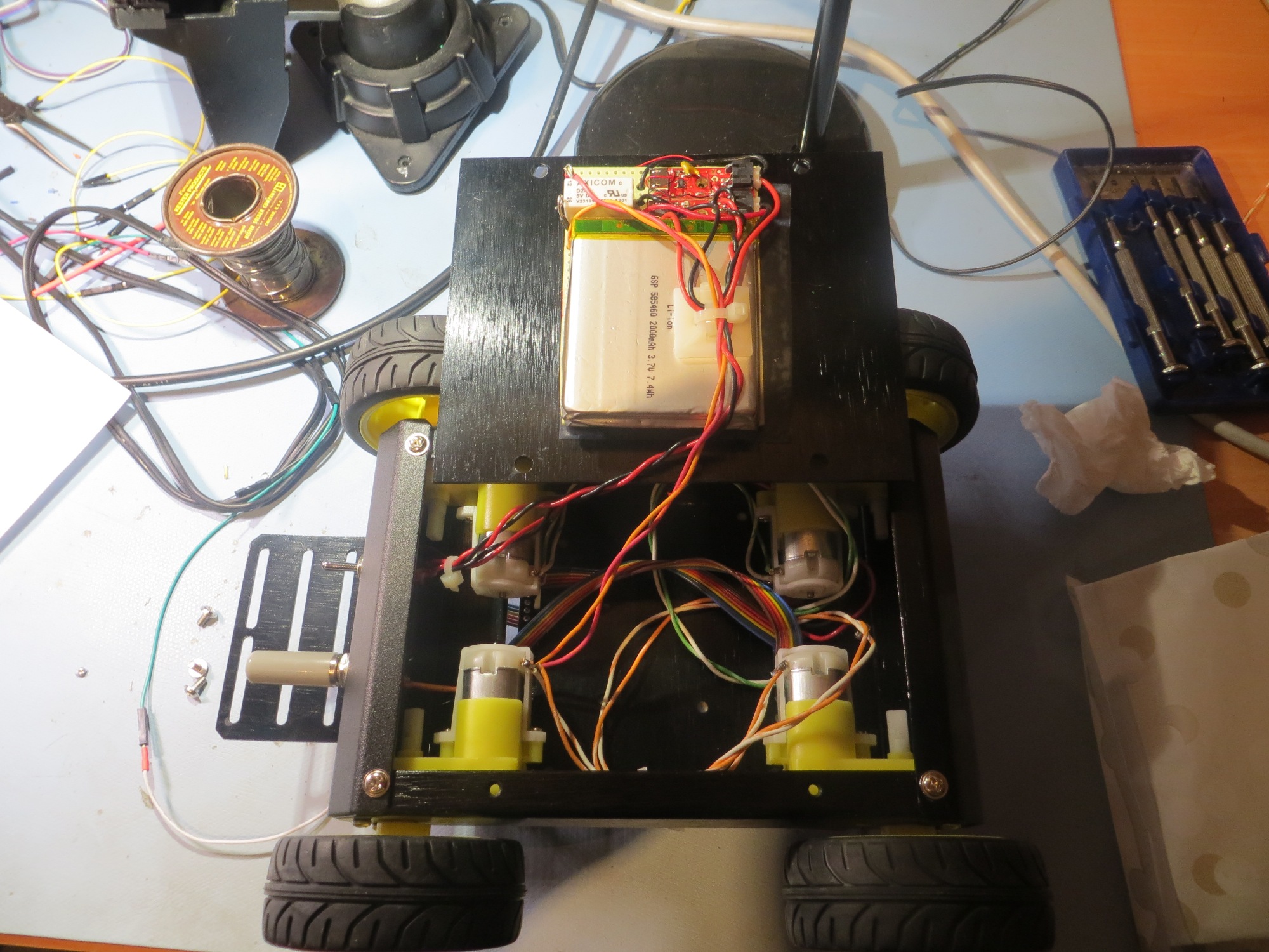
Battery pack being installed in the motor bay. Note power switch and charging plug on left
Battery pack installed in motor bay
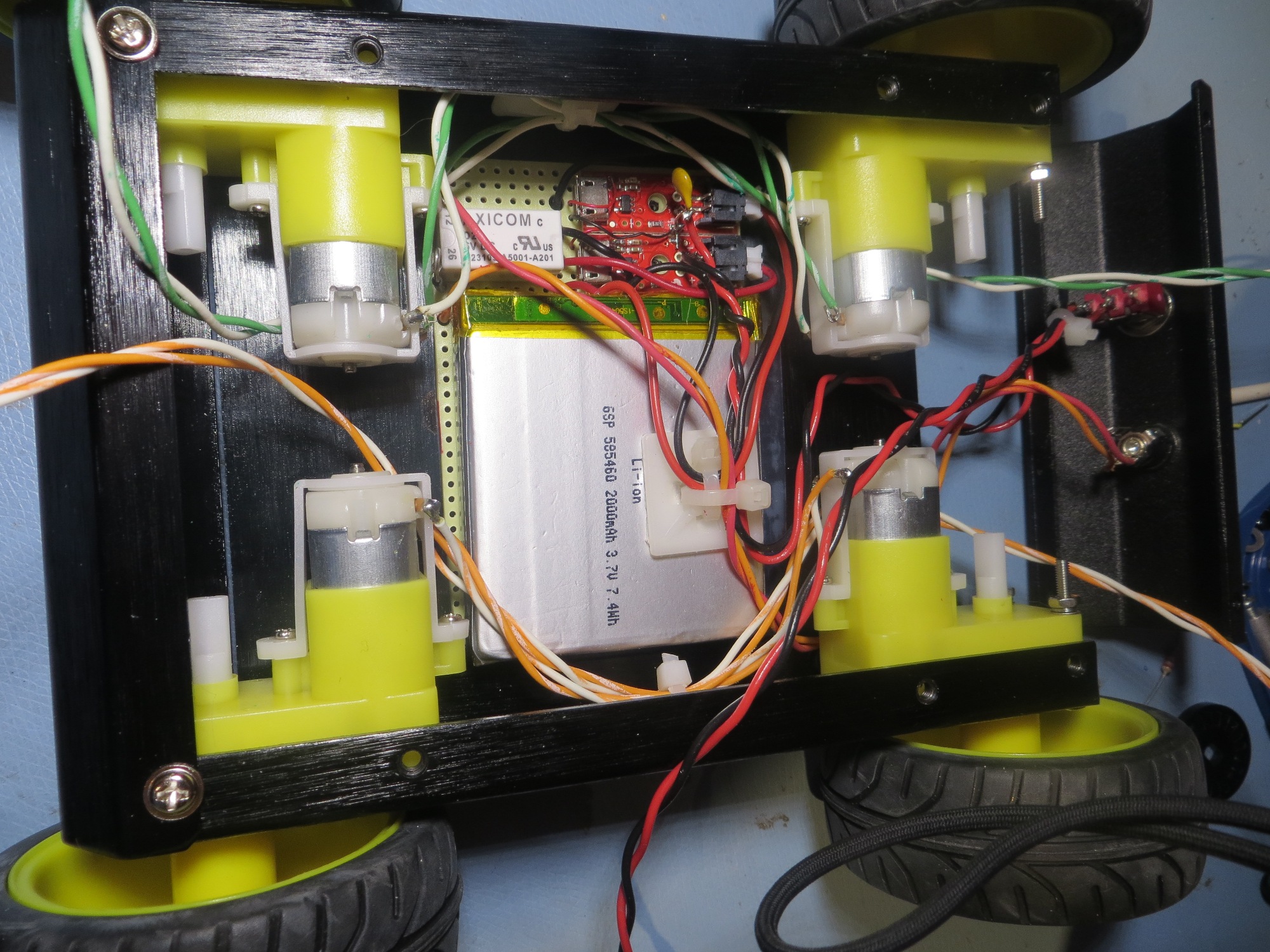
Battery pack installed in motor bay
Maintenance access to motor bay and battery pack
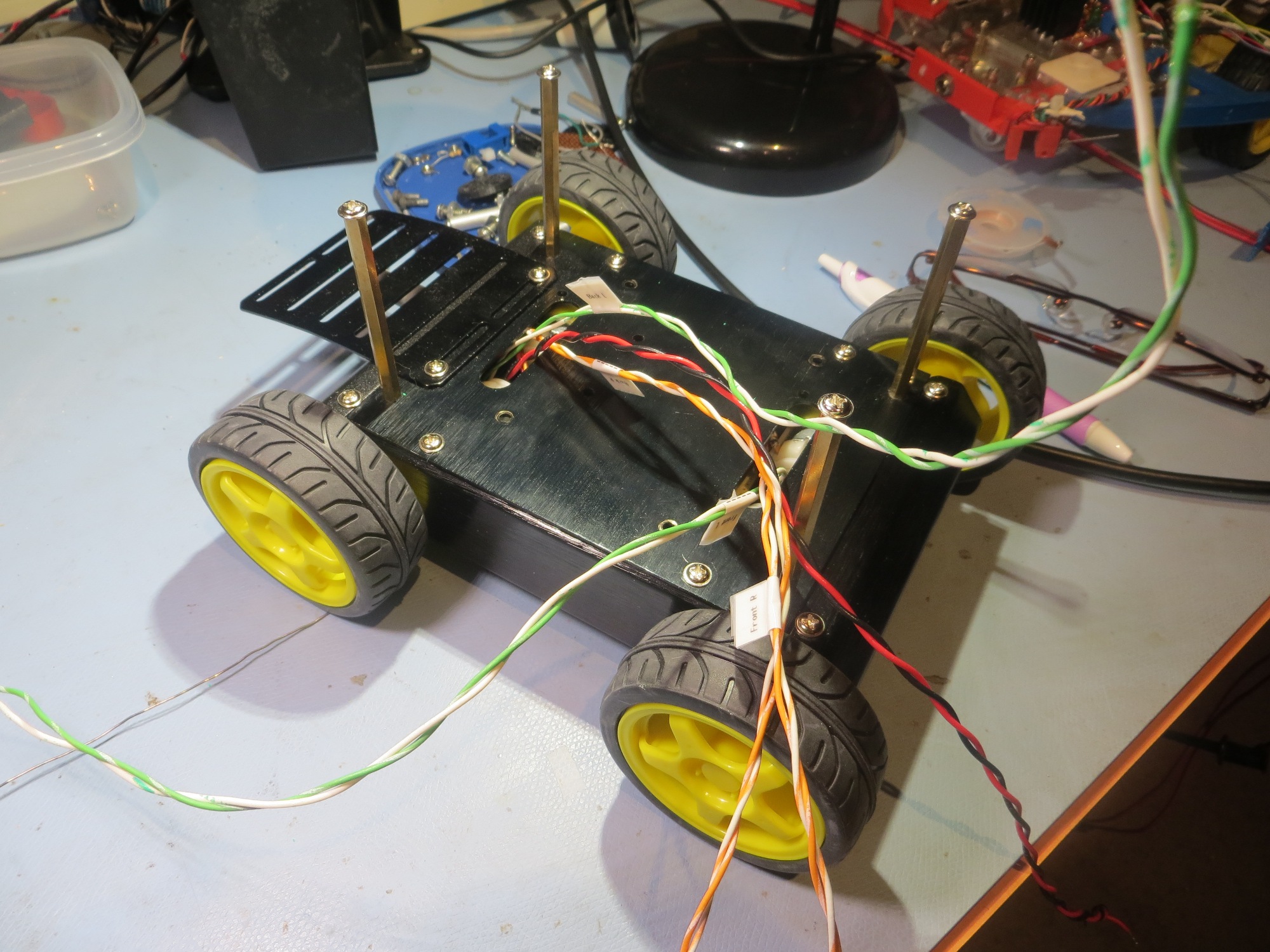
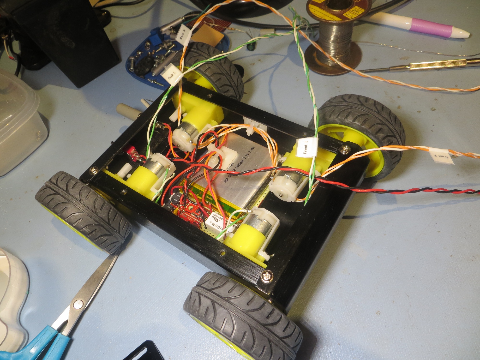
Motor bay closed, with motor and power wiring shown
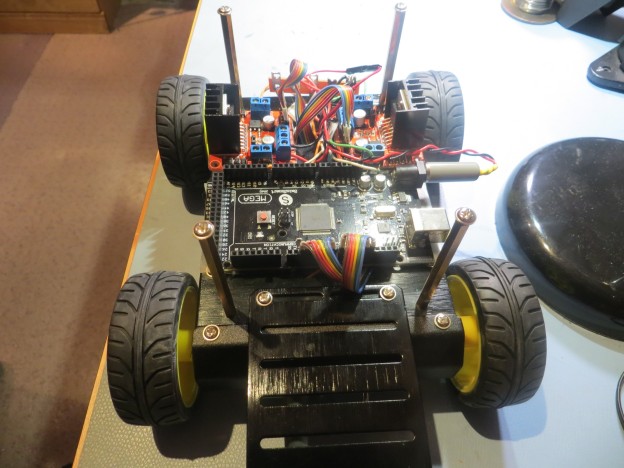
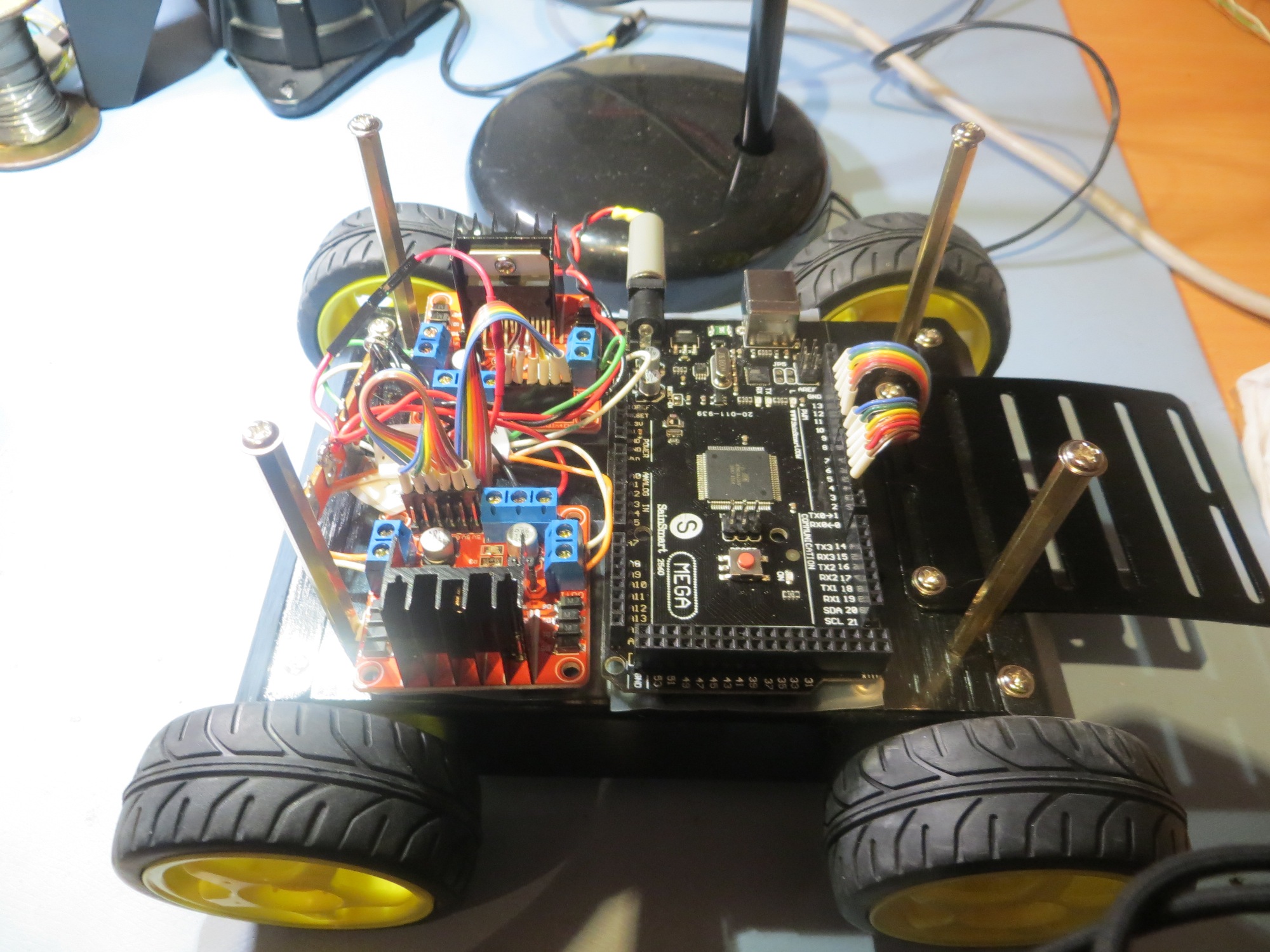
After getting the power pack installed and the motors wired, it was time to move on to the ‘main deck’ components – namely the Arduino Mega and the two dual-motor drivers. We spent some quality time trying different component layouts, and finally settled on the one shown in the following photo.
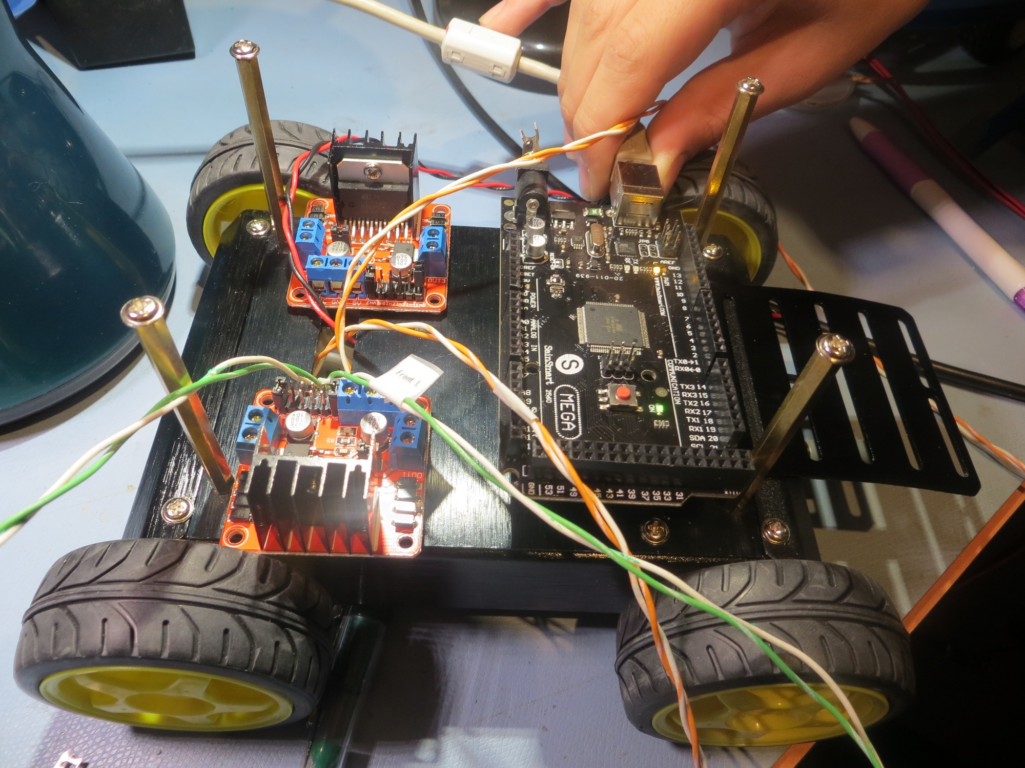
Initial component placement on the main deck
The motor drivers and the Arduino were mounted on the main deck plate by putting down a layer of adhesive-backed UHMW (Ultra-high Molecular Weight) teflon tape to insulate the components from the metal deck plate, and then a layer of double-sided foam tape to secure the components to the UHMW tape. In the photo above, the Arduino is mounted toward the ‘front’ (arbitrarily designated as the end with the on/off switch and charging plug), and the motor drivers are mounted toward the ‘rear’.
After mounting the motor drivers and the Arduino, we added a terminal strip at the rear for power distribution, ribbon cables from the Arduino to the motor drivers, and cut/connected the motor wires to the motor driver output lugs. The result is shown in the photos below.
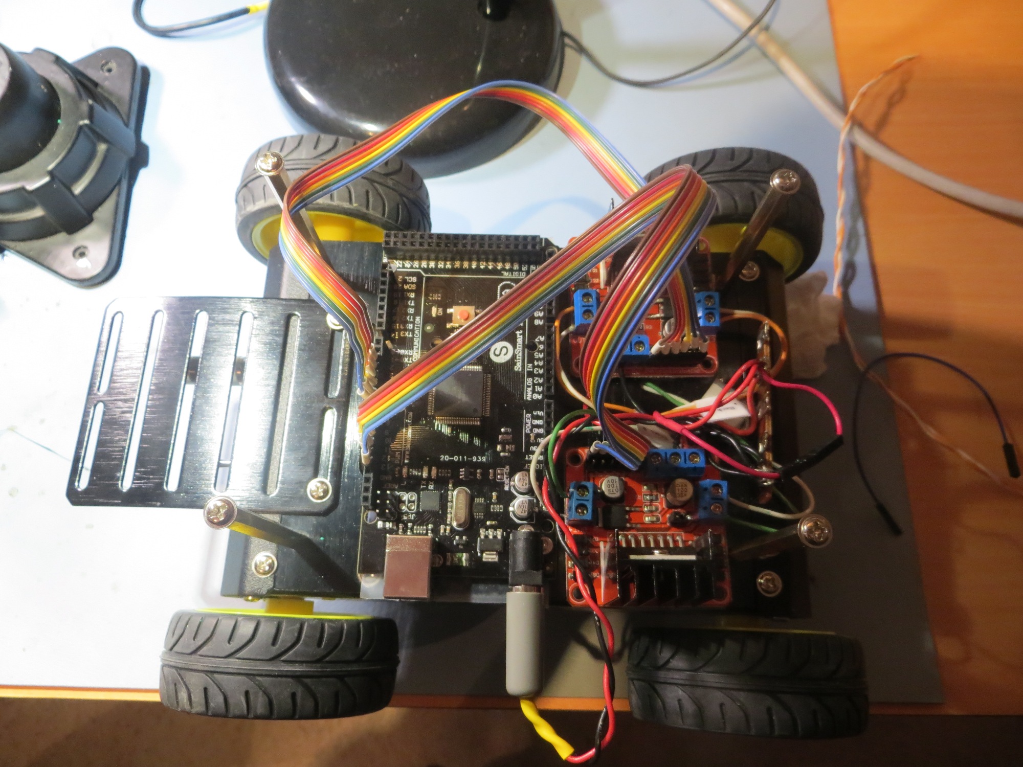
Ribbon cable initial installation
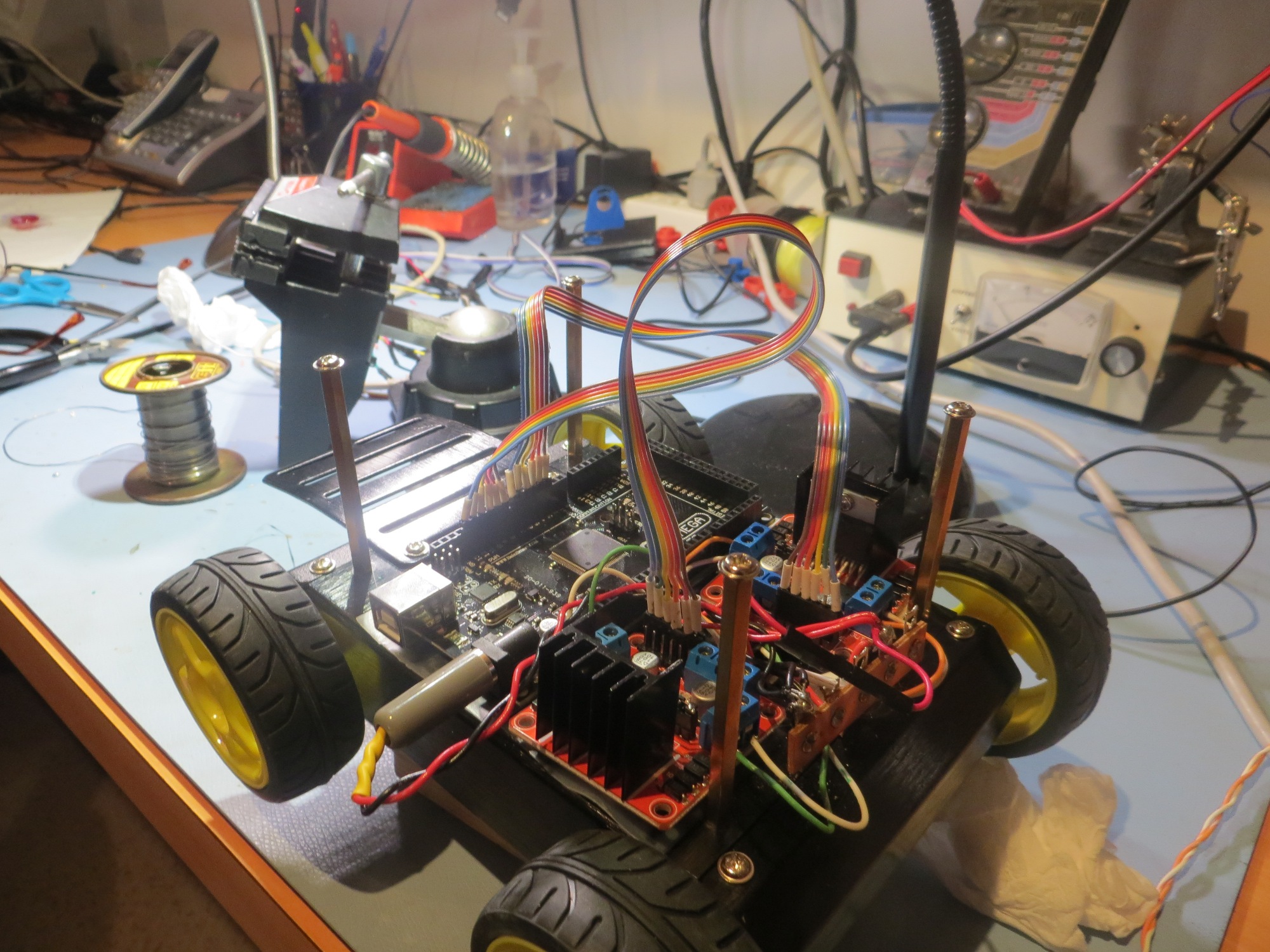
Ribbon cable initial installation
Final ribbon cable routing
To test this setup, we borrowed a nice demo program created by John Boxall of Tronix Labs. This demo was particularly nice, as it used the exact same flavor of L298-based motor driver as the ones installed on our robot, so very little adjustment was required to get the demo code to run our 4WD robot. After fixing the expected motor wiring reversal errors, and getting all the wheels to go in the same direction at the same time, we were able to video the ‘robot jig’ as shown below
So, at this point we have a working robot, but with no navigational capabilities. Now ‘all’ we have to do is add the XV-11 NEATO LIDAR on the sensor deck, get it to talk to the Arduino, and then get the Arduino smart enough to navigate.
Stay tuned! ;-).
Frank and Danny
Pingback: Building up the New 4WD Robot - Part 3 - Paynter's Palace