
Posted 16 September, 2015
Back in June of this year I posted about my initial efforts to implement a tachometer subsystem as part of a spinning-LIDAR system (see ‘LIDAR-Lite Gets its Own Motor‘), This implementation used a ‘plugged gap’ technique for detecting the index position of the LIDAR, as shown below.
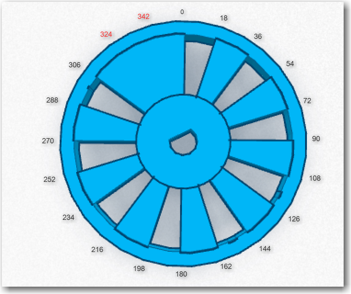
Diagram of the tach wheel for Wall-E’s spinning LIDAR system
The idea was that when the time between gap interrupts was more than 2 gap durations (assuming a relatively constant rotation speed), then the ‘plugged gap’ must be between the IR LED and the photo-diode. This design works OK, but has a couple of nagging drawbacks:
- It depends on a fixed open-loop timing delay; if the motor RPM varies enough, the fixed delay threshold might be too large or too small.
- The plugged-gap technique removes two interrupt positions from the wheel, meaning that position information is missing during that 54-degree arc.
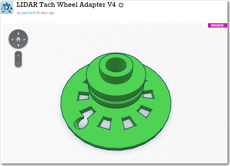
So, after getting my V2 ‘Blue Label’ LIDAR from Pulsed Light and figuring out how to use it (see this post), I decided to see what I could do about addressing both the above problems. At first I thought I might be able to simply add a second photo-diode on the sensor side of the tach sensor assembly, coupled to the existing single IR LED via a slanted channel in the tach wheel, as shown below. The idea was that when the interrupt was fired at the edge of the index gap, the value of the ‘other’ sensor could be read – if the value was below a certain threshold (meaning more impinging IR energy), then that sensor must be lined up with the index hole. This meant that the index hole needed to be offset from the index gap, so the max energy receive position would coincide with the position at which the interrupt fired, which occurs at the gap edges, not the center.
This turned out to be a miserable failure. The IR LED’s have a very narrow illumination sector, and there wasn’t enough off-axis energy to reliably detect the index hole.
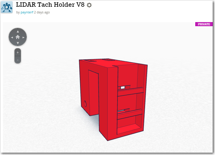
So, some five versions later, along with a complete redesign of the sensor assembly, I have what I think is a nicely working implementation. The single LED slanted-hole design was scrapped in favor of a two-LED/sensor one, and the index sensing hole was replaced by a circumferential gap, as shown below.
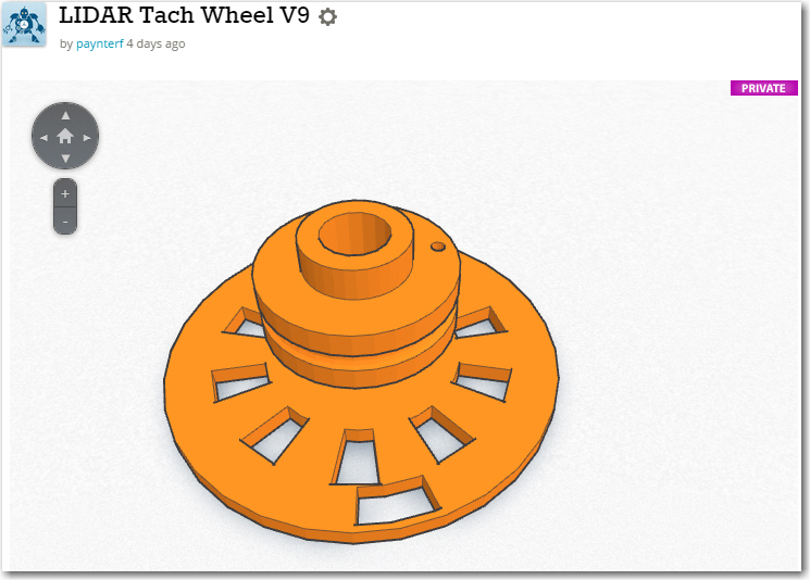
Latest two-sensor/LED design. Note the circumferential gap is centered on one edge of the index gap, so the index sensor voltage will be minimum (max incident energy) when the gap-edge interrupt fires.
For the tach sensor assembly, the single IR LED was replaced by two independent IR LED’s, each with its own 240-ohm current-limiting resistor (I tried running them in series with a single resistor, but that didn’t work very well either). The original enclosed sensor slot was replaced by an exposed ‘trough’ with two retainer bars (the trough without the retainer bars didn’t work either). See below for the ‘new improved’ tach sensor assembly.
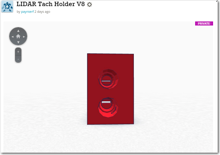
Tach sensor assembly showing the mounting holes for the two 3mm IR LED’s . The thin gaps visible in the background are the corresponding channels into the photo-diode trough
Tach sensor assembly showing the photo-diode trough. The backs of the photo-diodes are glued to a thin plastic carrier that is captured by the retaining bars
After running some preliminary tests, I mounted the new tach wheel and sensor assemblies and ran some O’scope tests to see how the new design worked. I was very pleased to see that it appears to be working better than I could have hoped. In the following O’scope photo, the top trace is the index sensor, and the bottom trace is the normal tach-gap sensor. Both are 2 volts/cm and exhibit full 5-volt swings.
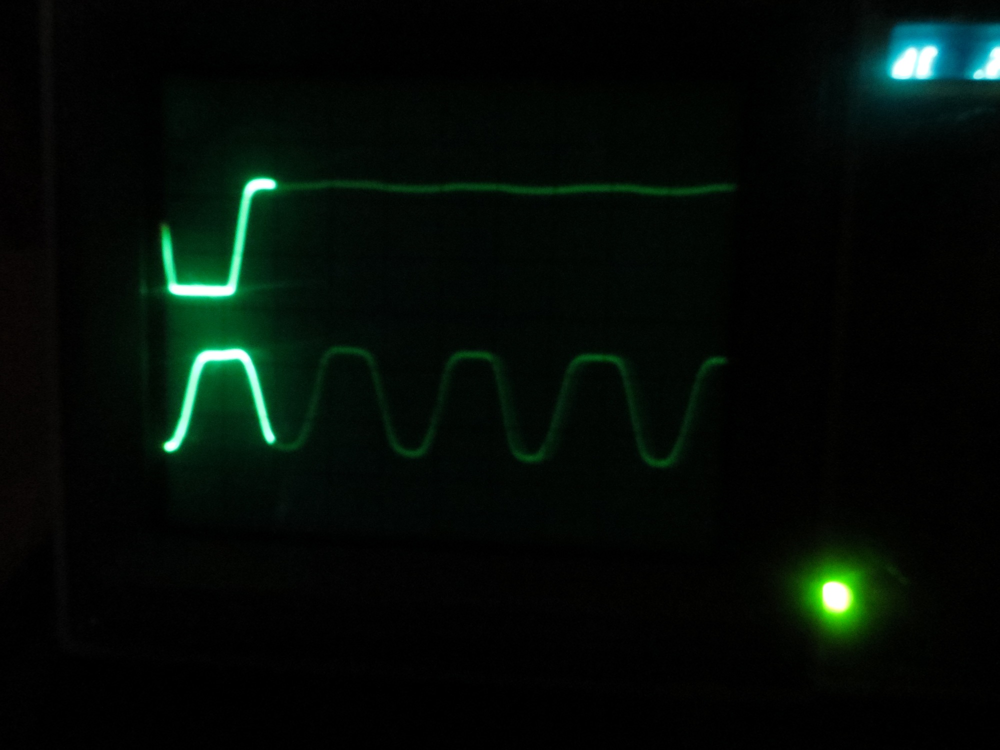
O’so;pe photo with the signal of interest highlighted. The top trace is the index sensor, and the bottom one is the tach-gap sensor. The index interrupt will occur at the first rising edge of the bottom trace.
The gap interrupt of interest occurs at the first rising edge of the bottom trace. As can be seen from the photo, reading the value for the index gap sensor (top trace) at this point will retrieve a stable ‘0’ value, perfect for index gap detection!
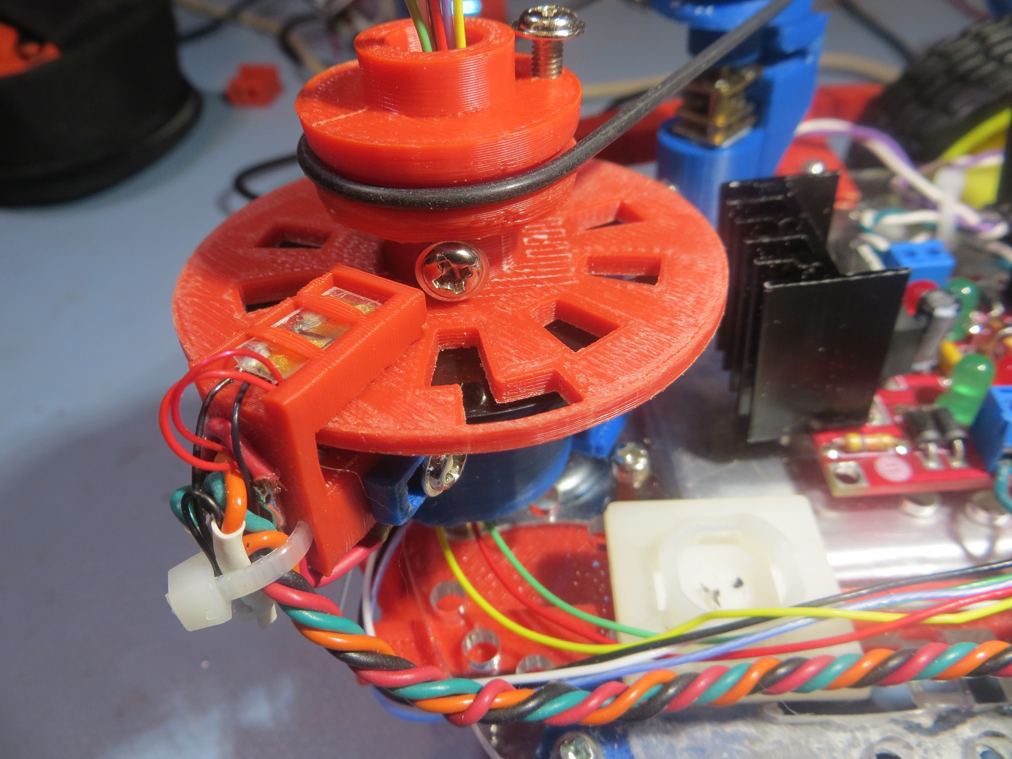
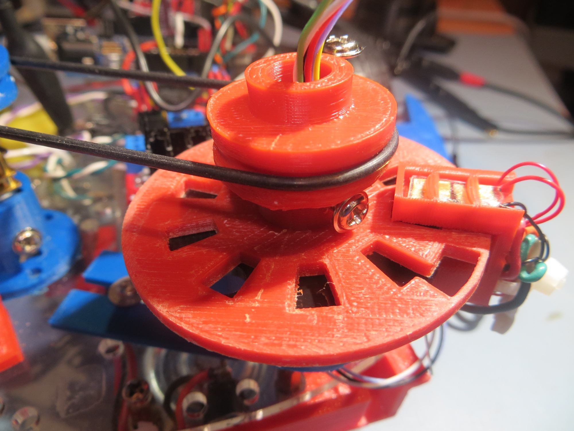
The following photos show the new tach wheel and sensor assembly mounted on Wall-E, with the LIDAR assembly removed for clarity.
Stay tuned for more test results from this configuration!
Posted 17 September, 2015:
After re-installing the LIDAR and making all the right connections (not a trivial task, btw), I fired the system up using my ‘DAFAP_Plus’ (that’s. “Distance as Fast as Possible’ plus modifications for interrupt handling) sketch and took some index sensor measurements. In the screenshot below, the ‘Sensor’ values are from the index sensor. As expected, they are near the top of the 10-bit A/D range for interrupt numbers 1-19 (a reading of 700 implies about 3.5VDC). However, the sensor reading for interrupt 20 is now much better than it was before; before implementing the improved LED driver and new tach wheel layout, the max readings were about the same, but the minimum reading was occasionally over 400 (i.e. about 2VDC) – making it harder to reliably discriminate between non-index and index gap cases. Now the index gap reading is a reliable ‘0’, providing a 3.5VDC differential – more than double the 1.5VDC differential before – yay!!
Another item of note in the readout below is the ISR Ms value. This is the time required to service the associated interrupt, including the time required for the Pulsed Light ‘Blue Label’ LIDAR to take a distance measurement. Note that all of these times are in the single digit range – meaning I could probably double the number of tach wheel gaps (i.e. double the system angular resolution) if I wanted to. Note that there is an extra value shown for each ‘interrupt 20’ line; this ‘Idx Ms’ value is the total time between index gap appearances, i.e. the total rotation time. So, the LIDAR is rotating just a tad shy of 120 RPM (2 RPS), which should be fast enough for decent wall-following navigation.
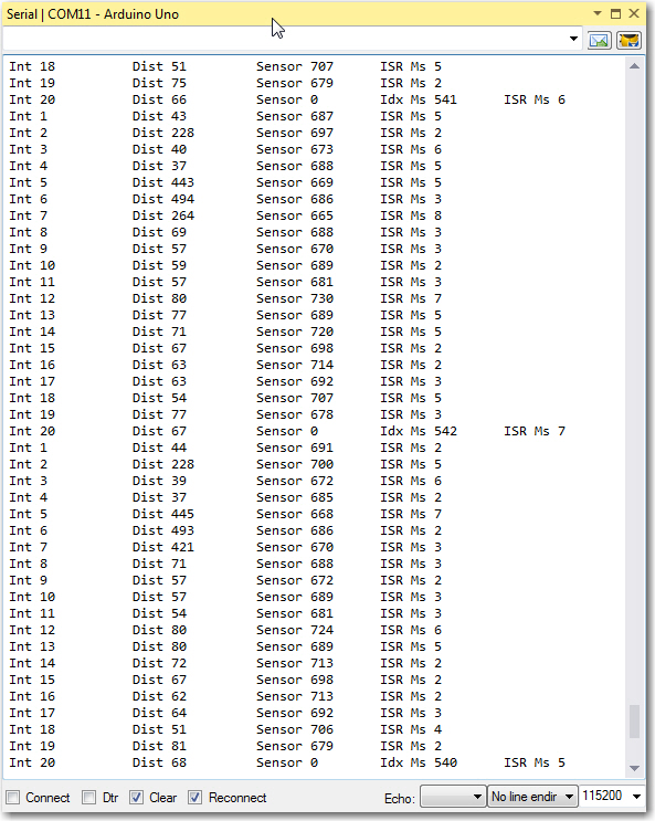
Log from a 17 Sept 2015 test run; note the ‘0’ sensor value at interrupt 20
Frank