30 September, 2015
Sad to say, but I believe I have ‘hit the wall’ on development of an effective spinning-LIDAR navigation system for Wall-E. Even with a souped-up spinning platform (approx 3 rev/sec), I have been unable to reliably navigate a straight hallway, much less recover from stuck conditions. In addition, the combination of drive motor currents and the increased current required to drive the spinning platform at the increased rate drains the battery in just a few minutes. So, I have reluctantly concluded that the idea of completely replacing the acoustic sensors with a spinning-LIDAR system is a dead end; I’m going to have to go back to the original idea of using the acoustic sensors for wall following, and a fixed-orientation LIDAR for stuck detection/recovery.
I started down the spinning-LIDAR road back in April of this year, after concluding a series of tests that proved (at least to me) that the use of multiple acoustic sensors was not going to work due to intractable multi-path and self-interference problems. In a follow-up post at the end of that month, I speculated that I might be able to replace all the acoustic sensors with a spinning-LIDAR system for both wall following and ‘stuck detection’. At the time I was aware of two good candidates for such a system – the NEATO XV-11 robot vacuum’s spinning-LIDAR subsystem, and the Pulsed Light ‘LIDAR-Lite’ component. I chose to pursue the Pulsed-Light option because it was much smaller and lighter than the XV-11 module, and I thought it would be easier to integrate onto the existing Wall-E platform. Part of the appeal of this option was the desire to see if I could design and build the necessary spinning platform for the LIDAR-Lite device, based on a 6-wire slipring component available through AdaFruit.
In the time since that post at the end of April, I successfully integrated the LIDAR into the Wall-E platform, but only recently got to the point of doing field tests. The first set of tests showed me that the original spin rate of about 120 RPM (about 2 RPS) was way too slow for successful wall following using my original ‘differential min-distance’ technique, and so I spent some time investigating PID control techniques as a possibility to improve navigation. Unfortunately, this too proved unfruitful, so I then investigated ideas for increasing the LIDAR’s spin rate. The LIDAR spinning platform is driven by a drive belt (rubber O-ring) attached to a pulley on a separate 120 RPM DC motor. My original setup used a pulley ratio of approximately 1:1, so the motor and LIDAR both rotated at approximately 120 RPM. By increasing the diameter of the drive pulley, I was able to increase the LIDAR rotation rate to approximately 180 RPM (about 3 RPS), but unfortunately even that rate was too slow, and the increased drive motor current rapidly drained the batteries – rats!

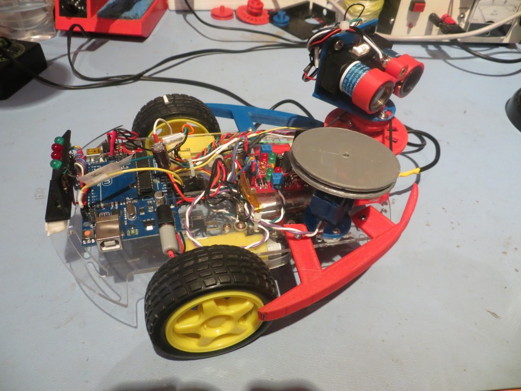
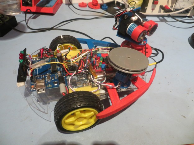
‘The Last Spinning LIDAR’ version. Note the large gray drive pulley. Gets the spin rate up to around 180 RPM, but at the cost of much higher battery drain.
So, while I had a LOT of fun, and learned a lot in the process, it’s time to say ‘Sayonara’ to the spinning-LIDAR concept (at least for Wall-E – still plan to try the XV-11 module on the 4WD robot) and go back to the idea of using acoustic sensors for wall following and a forward-looking LIDAR for obstacle avoidance and ‘stuck’ detection.
Stay tuned!

Pingback: Re-working Wall-E, Part I - Paynter's Palace
Pingback: Wall-E goes back to basics; Ping sensors and fixed forward-facing LIDAR - Paynter's Palace