Posted 08/24/2015
Progress on the Pulsed Light ‘Blue Label’ spinning LIDAR system has been put on hold for a few days pending the arrival of some 3mm IR LEDs needed for an upgraded tach sensor wheel, so I am passing the time working on the alternative system, the XV-11 LIDAR module from the NEATO vacuum.
Back in May of this year I posted some results where I mated the Teensy 2.0 based Get Sureal XV-11 module controller (see the post here) and got very good results with a LIDAR ‘image’ of the walls of a cardboard box. After this effort, I put the XV-11 aside for two reasons; first, I received a ‘Silver Label’ (V1) LIDAR-Lite unit from Pulsed Light and was having too much fun designing and implementing a spinning-LIDAR system, and second, I couldn’t figure out how to get the XV-11 data into my robot controller (an Arduino Uno). The Teensy 2.0 XV-11 controller parses the data stream from the XV-11, routes it upstream to the USB host, processes commands from the USB host, and maintains the XV-11 rotation speed using a PID controller. This is all well and good, but the Uno isn’t a USB host, and adding that capability would be a major PITA. So, I put the whole thing on the back burner, hoping that inspiration would strike at some later date.
Now, almost three months later, I had some ideas I wanted to try to achieve the goal of getting the XV-11 streaming data onto the Uno robot controller so that it could be used for navigation.
The Problem(s):
The XV-11 LIDAR module streams angle, position, data-quality, and RPM information over a serial connection to the Teensy 2.0 controller, and there is a LOT of it. The XV-11 rotates at a nominal rate of 300 RPM, i.e. 5 RPS. During every 200 msec rotation, it sends 360 (at least) data groups, where each data group contains pointing angle (0-360), distance (in cm, I think), a data quality metric, and RPM. Each data group must be parsed to extract the needed information. The Teensy firmware also provides a PWM waveform to control the XV-11’s rotation speed, based on the RPM values being reported over the serial port.
The Teensy 2.0 boasts two hardware serial ports, but one is used for the connection to the upstream USB host, and the other one is used to receive the data from the XV-11. So, no easy way to get the needed XV-11 data from the Teensy to the Uno – bummer :-(. And, even if the Teensy had a third hardware serial port, the Uno only has one – and it is used to connect to its upstream USB host – double bummer :-(.
And, even if I could figure out a way to get the data over to the Uno, how was I going to keep the data stream from swamping the Uno’s (or the Teensy’s) very finite resources. With the spinning LIDAR system, I only capture 18 data groups/revolution, and even this amount threatens to blow out the top of working memory. There is no way it can handle the 360 data groups from the XV-11. Moreover, those data groups are arriving at about twice the rate of the groups from the Pulsed Light spinning LIDAR system.
The (partial) Solution – Software Serial to the Rescue!:
In between times where I was actively working on the Pulsed Light spinning LIDAR project, I kept returning to the problem of how to get XV-11 data into the Uno, and in my wanderings through the online Arduino world I ran across references to ‘Software Serial’, where virtual serial ports could be implemented using two of the Arduino GPIO pins. This sounded intriguing, but all the available libraries come with baggage of one sort or another; one can’t send/receive simultaneously, another can do that, but is sensitive to other interrupts… Then, just the other day I ran across ‘SimpleSoftSerial’ a version written by ‘Robin2’ just for the Uno (see the post here). The whole thing is just a ‘.ino’ file, not a library at all, and it does exactly what I want – YAY! Having the ability to add another serial port to the Uno solves part of the problem, so I decided to see if I could get just this part going, and maybe figure out the data management issue at some future time.
Robin2 also kindly provided a pair of Arduino sketches to demo the ‘Simple SoftSerial’ capability. One part runs on a Uno (of course, as that is the target processor for this little hack) and the other ‘Partner’ program runs on (in his case) a Mega as it requires multiple hardware serial ports. I didn’t have a Mega handy, but I did have the Teensy 2.0 that came with the Get Sureal XV-11 controller, and it has two hardware serial ports. So, I disconnected the XV-11 LIDAR module from the Teensy, and temporarily re-purposed it for this test.
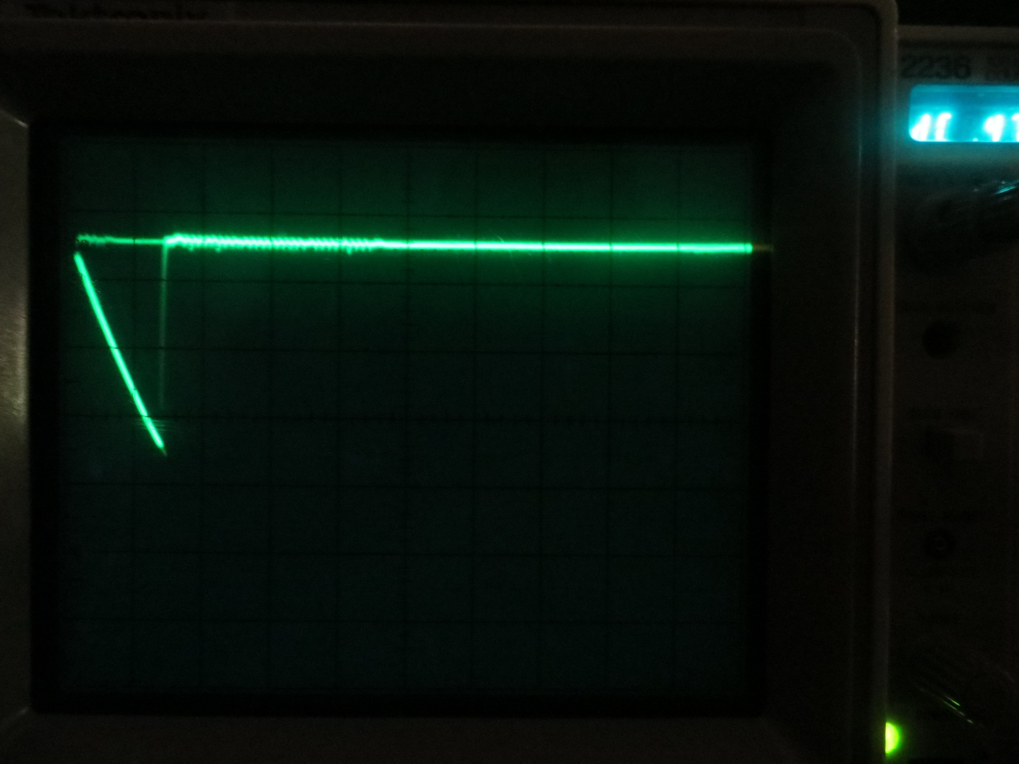
I loaded ‘DemoPartner.ino’ onto the Teensy, and ‘DemoSimpleSoftSerial.ino’ onto a spare Uno, connected the two using a pair of jumpers, and voila – it ‘worked’ but only in one direction. I was able to see characters transmitted on the Uno showing up on the serial monitor port on the Teensy, but not the other way around. I had previously used my trusty O’scope to probe the pins of the connector from the Teensy to the XV-11 module, and thought that I had determined which pin was Tx and which was Rx, but clearly something wasn’t adding up. At first I thought I just had a loose connection with my jumper leads, but after some more fiddling, I became convinced that wasn’t the problem. With my ‘scope, I probed the actual Teensy board Tx pin (D3), and discovered that the Teensy serial data was there, but it wasn’t making it to the XV-11 connector pin! Initally this seemed unlikely, as The Teensy/XV-11 combination was working fine – until the realization hit me that the XV-11 is a transmit-only device – there is no serial traffic going from Teensy to XV-11, and therefore there is no need to have the Teensy’s Tx pin connected to the XV-11 connector! After confirming this theory using a continuity checker, I bypassed the XV-11 connector entirely by soldering a 2-pin header onto the (fortunately side-by-side) Tx & Rx (D3 & D2 respectively) pins of the Teensy module. Once I made this change, I started seeing bi-directional data transmissions as advertised.
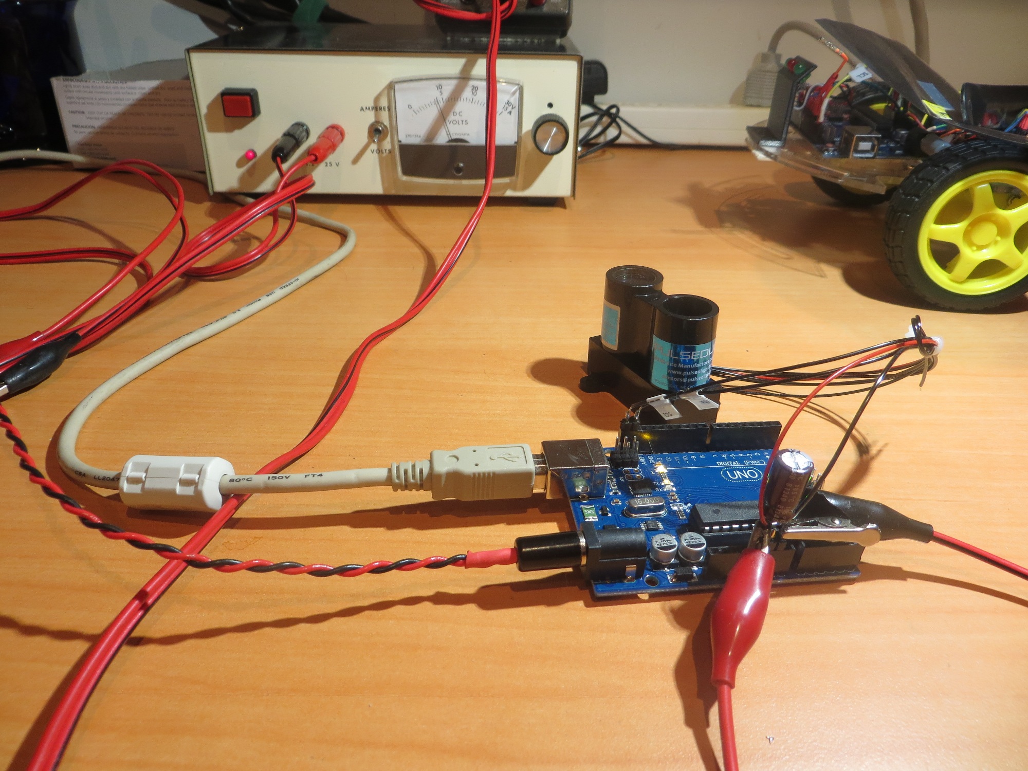
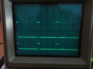
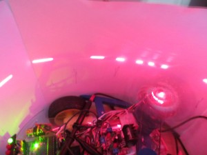
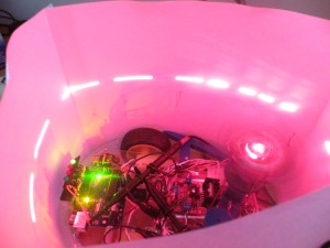
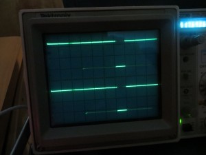
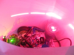
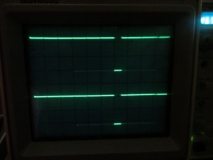
The following photo shows the experimental setup, with the temporarily disconnected XV-11 module in the background. I have also included a screenshot of the serial port monitors for both the Teensy module (running the ‘Partner’ sketch) and the Uno (running the ‘Demo’ sketch), on two separate instances of Visual Studio 2013/Visual Micro.
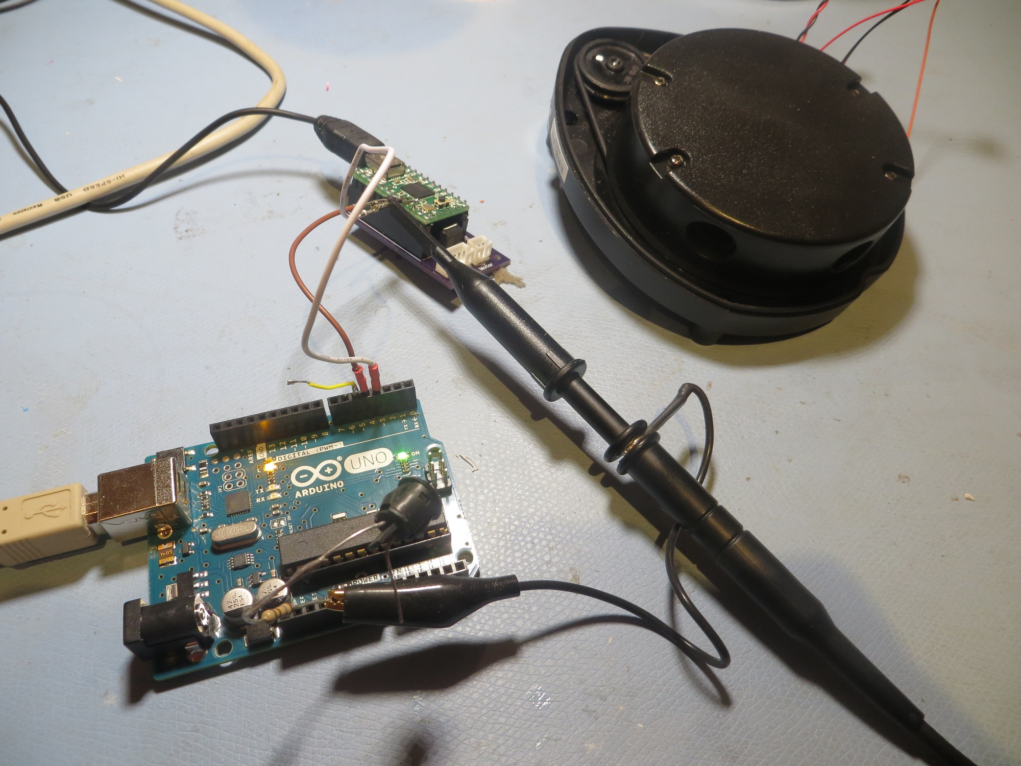
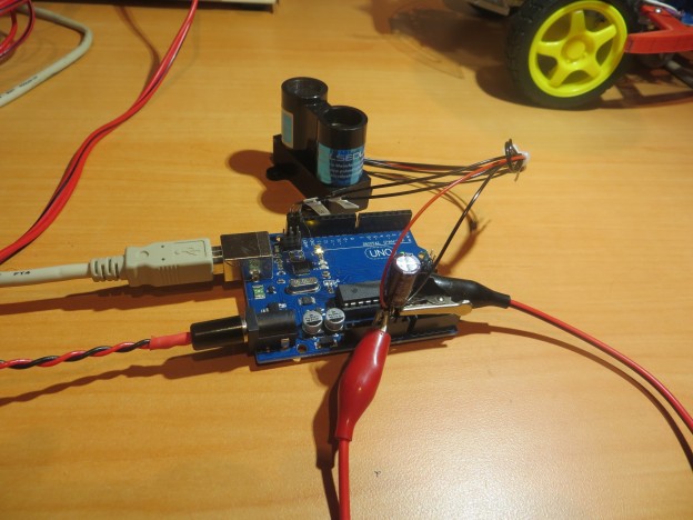
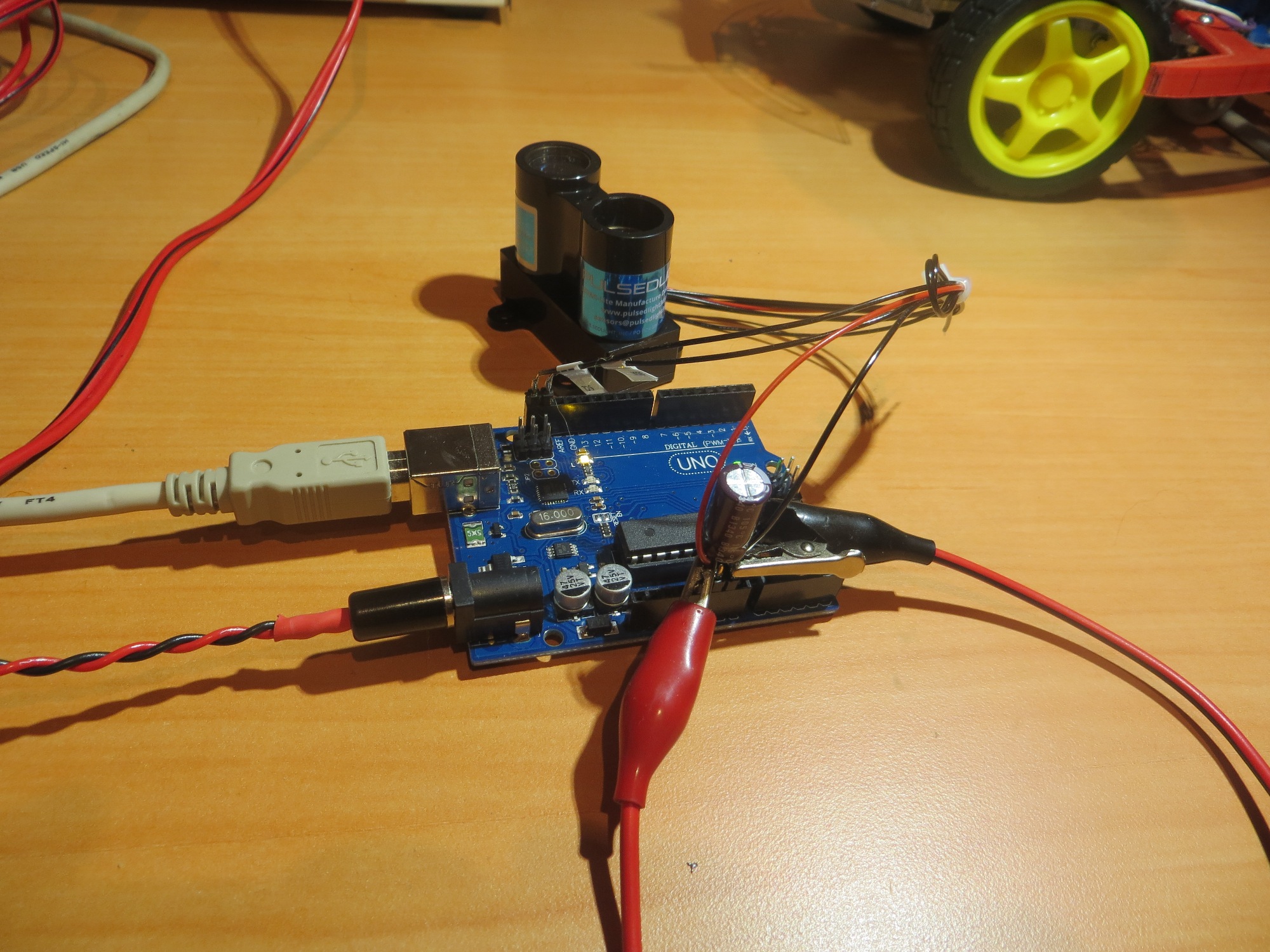
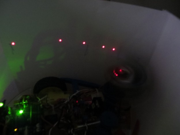
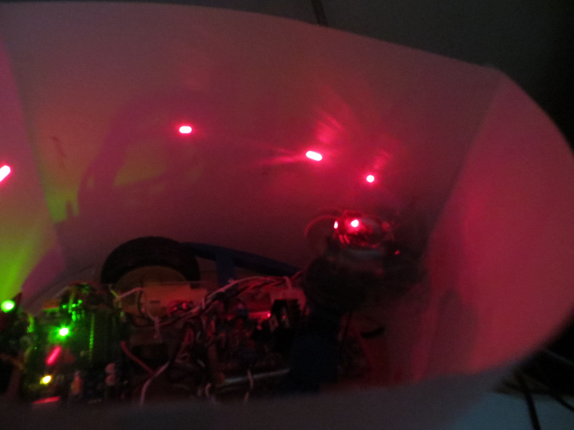
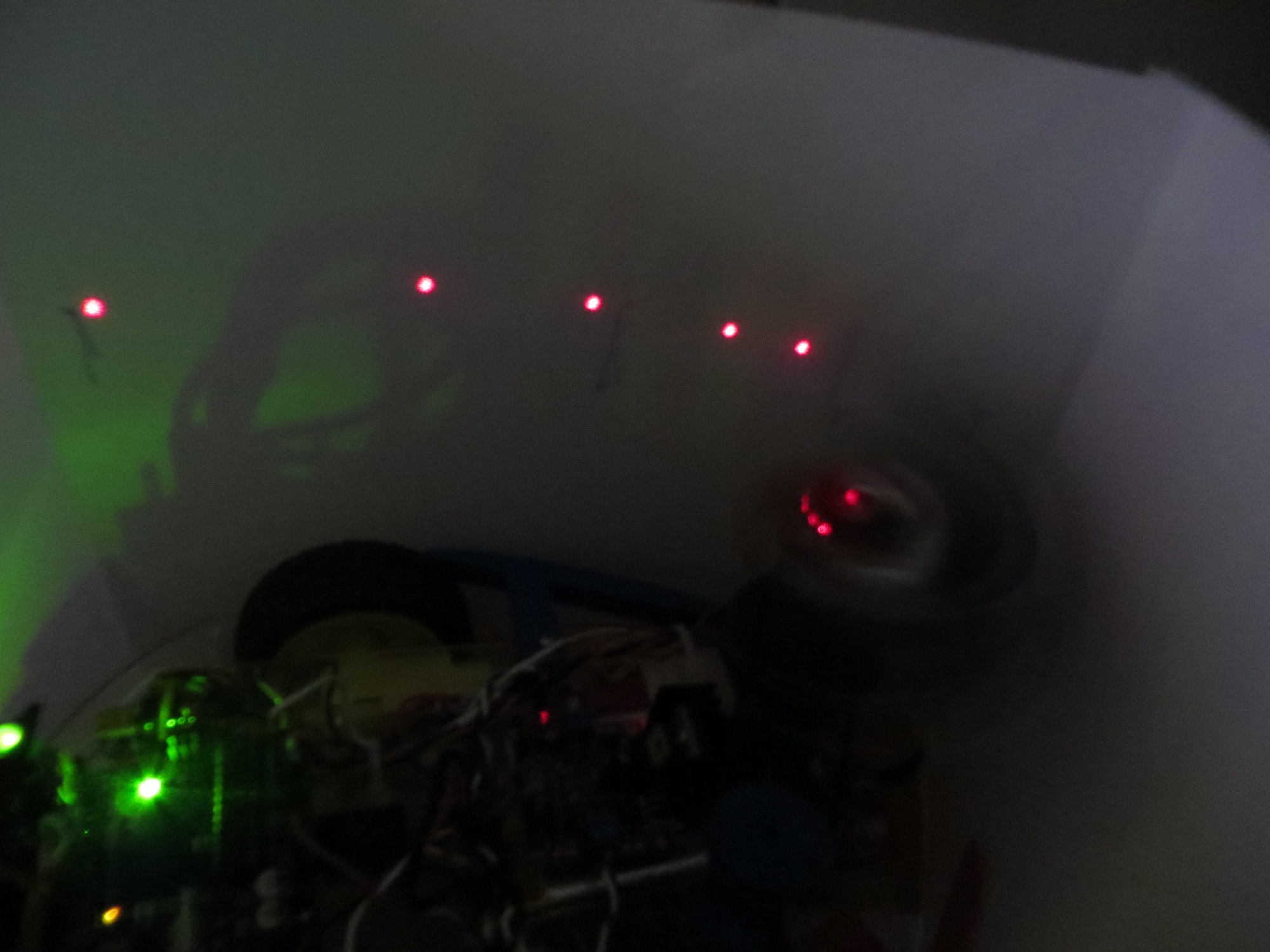
Experimental setup. Uno in foreground, Teensy and (temporariliy disconnected) XV-11 LIDAR module in background
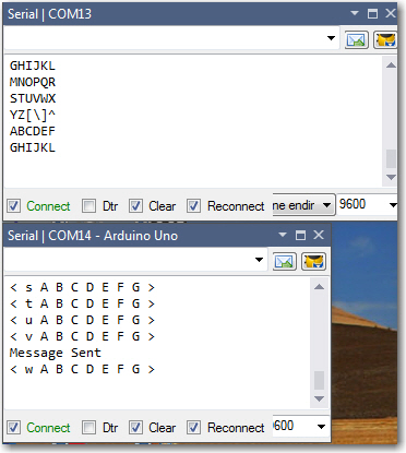
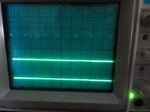
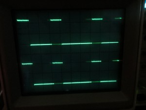
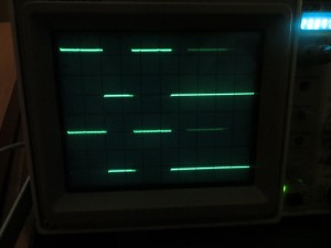
Screenshot showing serial port monitors from Uno (bottom) and Teensy (top).
Now that I have demonstrated the basic Uno virtual serial port capability, I plan to try and use this capability to get XV-11 serial data into my Uno motor controller by piggy-backing on the Teensy 2.0’s serial connection to the XV-11.
My plan is to return the Teensy module back to its original configuration, connected to the XV-11 via its second hardware serial port and running the Get Sureal processing sketch. Then I’ll put that same sketch on the Uno, but modify it to use the virtual serial port set up via the ‘Simple SoftSerial’ capability. If I do it correctly, I should be able to see the XV-11 data on both the Teensy 2.0 and Uno USB host serial monitors.
Stay tuned!
Frank
8/25/2015 Late addendum. Tried that trick and it didn’t work :-(. Turns out the virtual serial port isn’t anywhere near fast enough. Advertised speed is 9600 bps, with some speculation that it will work at 14200. Unfortunately, the XV-11 runs at 115200. So, I’ll either have to abandon the virtual port idea (and the Uno processor!) or figure out a way of slowing the XV-11 output down, or something else entirely. Bummer