Posted 5/29/15
In previous posts I described a couple of LIDAR alternatives to my original ultrasonic ping sensor system for Wall-E’s navigation capabilities, and the challenges I faced in implementing them. The LIDAR-Lite module is easily interfaced to an Arduino controller via the I2C interface and there is plenty of example code for doing this. However, in order to use it as the primary navigation sensor, it needs to spin at a controlled 1-5 RPS (60-300 RPM) and there has to be a way to determine the rotational angle associated with each distance measurement. In a previous post (http://gfpbridge.com/2015/05/dc-motor-speed-control-using-optical-tachometer/) I described my experiments with one of Wall-E’s wheel motors to implement speed control using an IR LED/photodiode/toothed-wheel tachometer.
After successfully implementing speed control on Wall-E using the right wheel motor, I next turned my attention to implementing a drive train to connect the wheel motor to the LIDAR Lite unit. I couldn’t just connect the LIDAR module to the motor shaft, as the LIDAR wiring would simply wrap itself to death as soon as the motor started turning. I had previously acquired the slip ring module (described in http://gfpbridge.com/2015/04/robot-of-the-future-lidar-and-4wd/) shown below
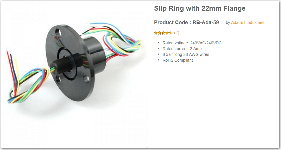
Adafruit Slip Ring with 6 contacts
So I needed a way to connect the rotating part of the slip ring to the LIDAR module, and the non-rotating part to the robot chassis and (via a drive belt) to the motor shaft.
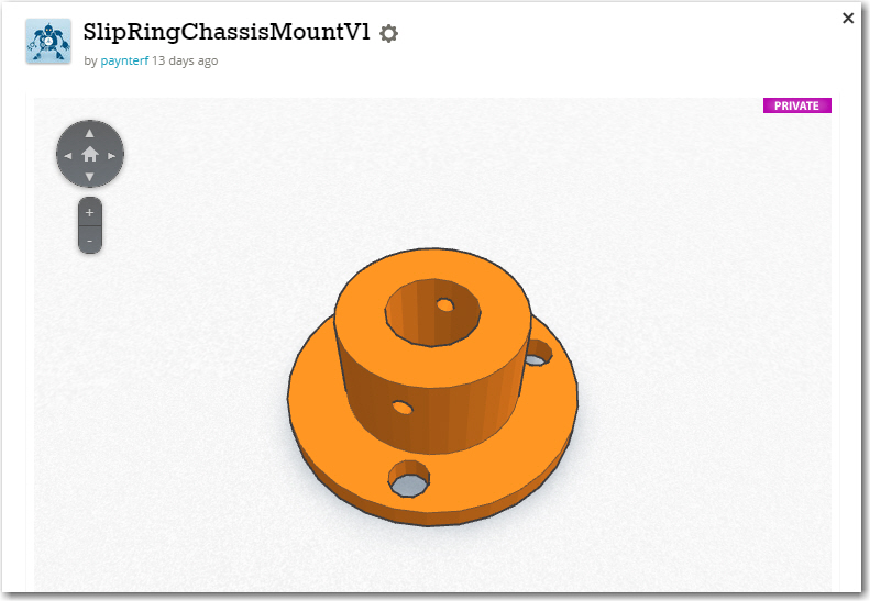
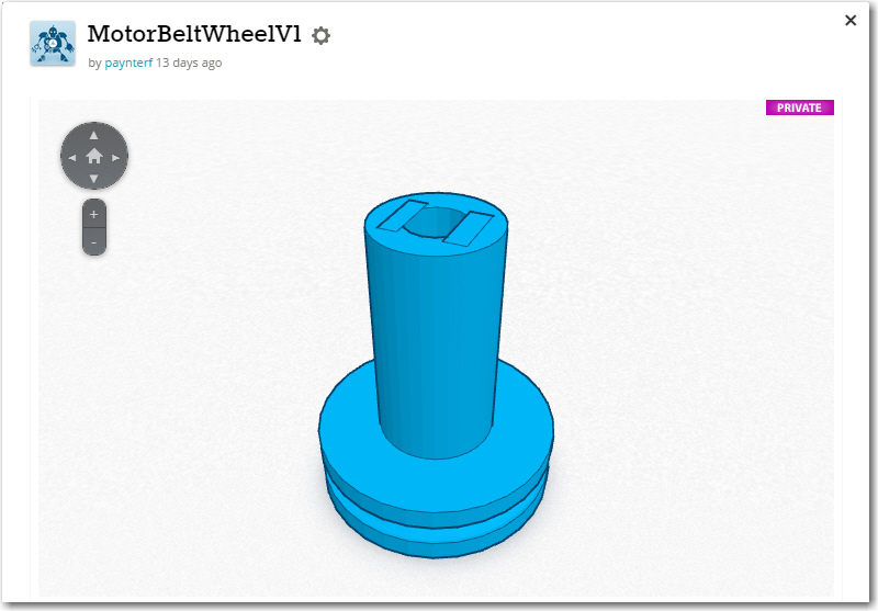
In TinkerCad, I designed a grooved pulley with a rectangular cross-section axial hole to fit over the motor shaft, an adapter from the rectangular LIDAR mounting plate to the cylindrical slip ring rotating side, and a chassis mounting bracket that would allow the non-rotating side of the slip ring to be adjusted toward and away from the motor shaft pulley to properly tension the drive belt. The drive belt is a standard rubber O-ring from McMaster Carr.
Now that I have motor speed control working and the LIDAR spinning, I need to connect the LIDAR electrically to the Arduino Uno controller and see if I can actually collect angle-specific LIDAR distance data (distance from the LIDAR, angle from the wheel speed tachometer control software). Stay Tuned!
Frank
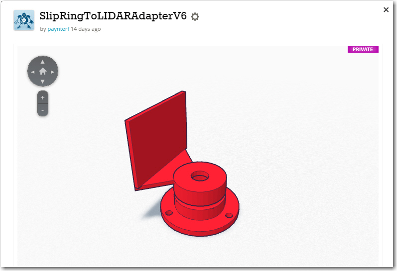

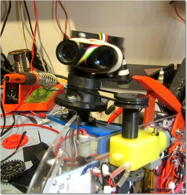
Spinning LIDAR drive assembly and LIDAR unit. Note O-ring drive belt.
Pingback: LIDAR-Lite Gets its Own Motor - Paynter's Palace