Monthly Archives: April 2015

New ‘stuck’ Detection Scheme, Part VI

Posted 04/10/15

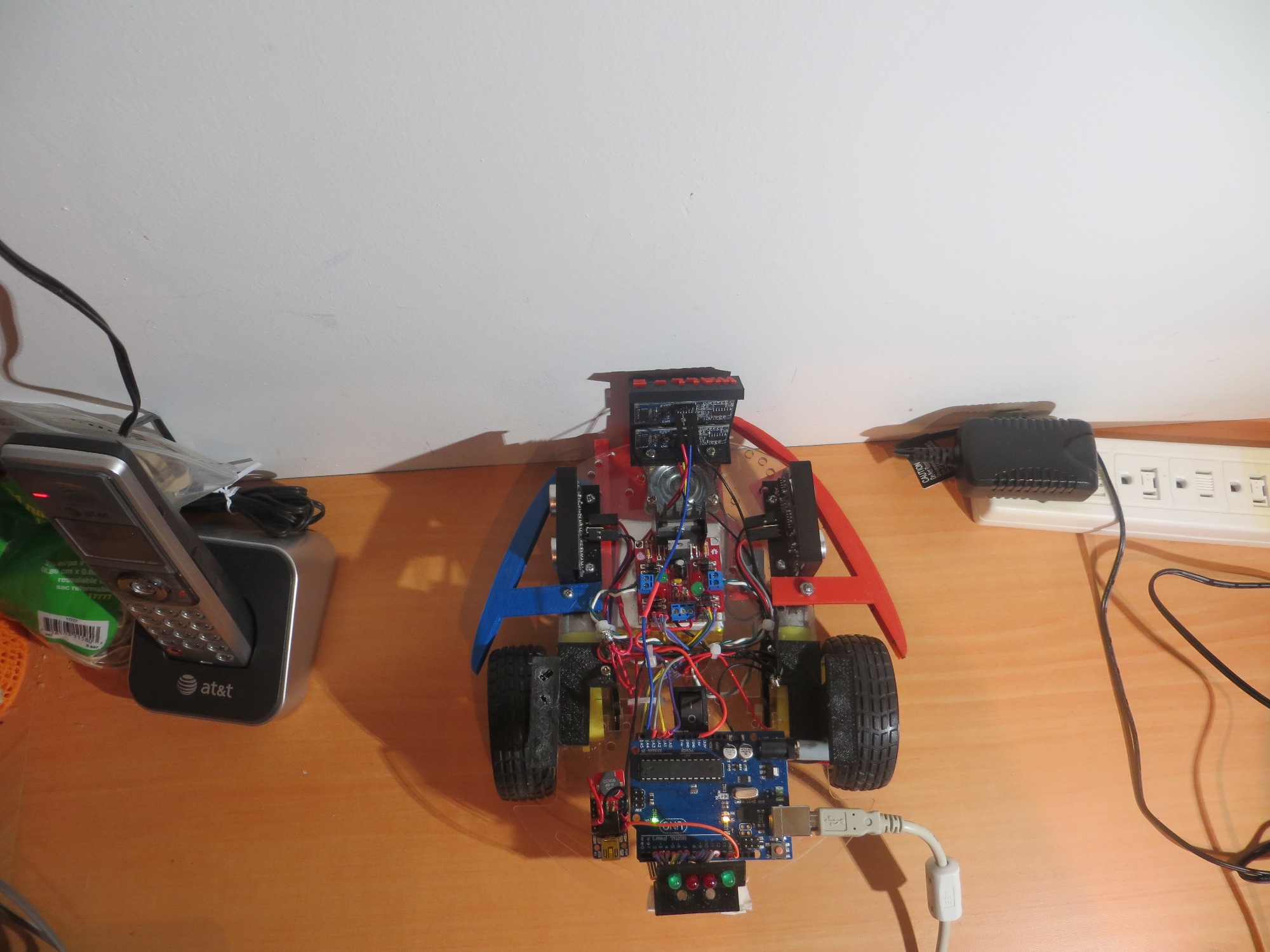
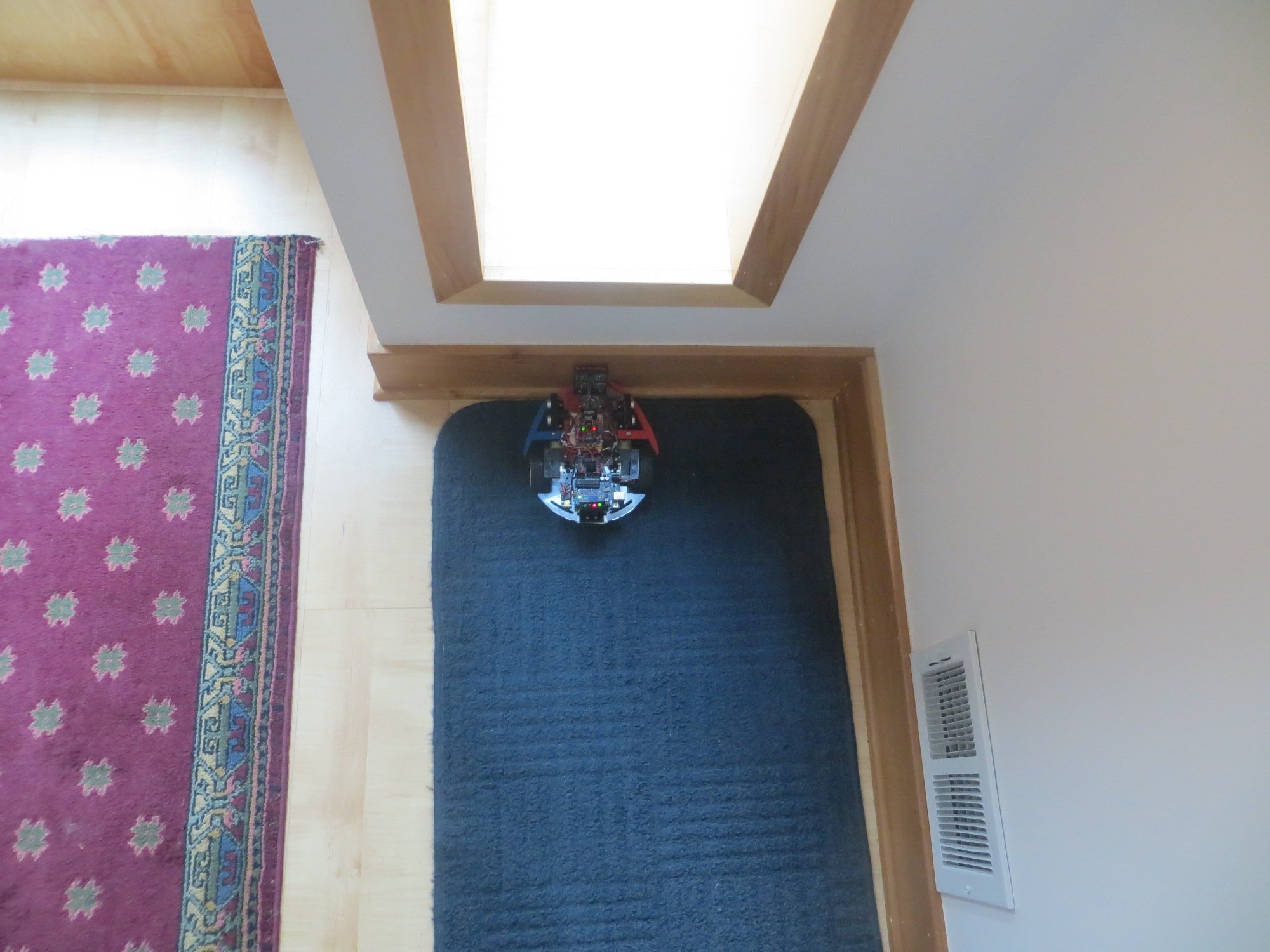
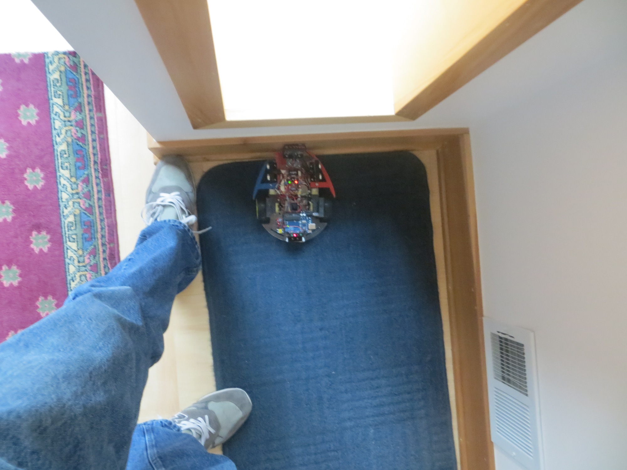
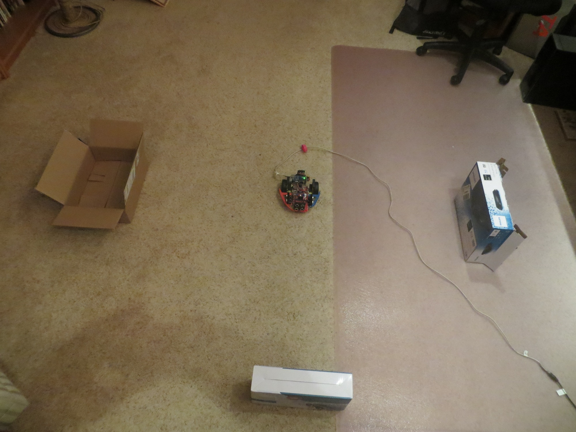
After an exhaustive (and exhausting!) set of ‘indoor range’ tests that (I thought) gave me a very good understanding of the ‘stuck’ detection issue, I made the changes I thought were necessary and sent Wall-E back out into the real world – where he promptly got stuck and  didn’t  recover! He got stuck climbing up onto the lip of a rug – and sat there merrily grinding away for what seemed like forever (but was only for a minute or so) before I took mercy on it.

Clearly the situation ‘in the field’ isn’t quite as simple as my ‘indoor range’ configuration, but the differences are  not obvious.  In an effort to figure this out without running around in circles, I’m trying to change just one thing at a time, as follows:

  • Changed the ‘STUCK_DIST_DEVIATION_THRESHOLD’ from 5 cm to 10 cm.  This helped a little, and didn’t seem to increase the frequency of false positives significantly.
  • Changed the  MAX_DISTANCE_CM from 200 cm to 100 cm, on the theory that in the ‘real world’ there is more clutter beyond 100 cm that can cause significant measurement deviation.  This change caused Wall-E to declare a ‘stuck’ condition almost continually – and I have no idea how  THAT happened!
  • Changed the  MAX_DISTANCE_CM back to 200 to verify that Wall-E’s behavior changed back to what it was before the change.  Check.
  • Changed the  MAX_DISTANCE_CM back to 100 and removed the guard code around the call to  UpdateWallFollowMotorSpeeds() in  MoveAheadTilStuck().  Changing the MAX_DISTANCE_CM back to 100 caused the false ‘stuck’ declarations to resume, and removing the guard code had no effect one way or the other.

So, what’s the deal with changing the MAX_DISTANCE_CM parameter?  It is only used in two places in the code – in the NewPing() constructor for all four sensors, and in the line ‘frontdistval = (frontdistval > 0) ? frontdistval : MAX_DISTANCE_CM + 1; in  MoveAheadTilStuck().  This line converts a zero reading from the front sensor to  MAX_DISTANCE_CM + 1 (101 in this case).  Since I’m no longer using the front sensor reading for the ‘stuck’ determination, I have no clue why this line (or lack of it, for that matter) would make any difference.

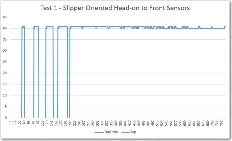
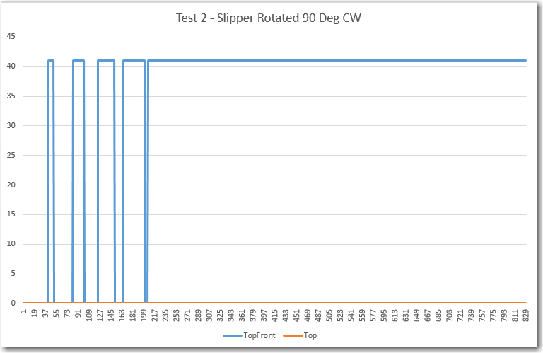
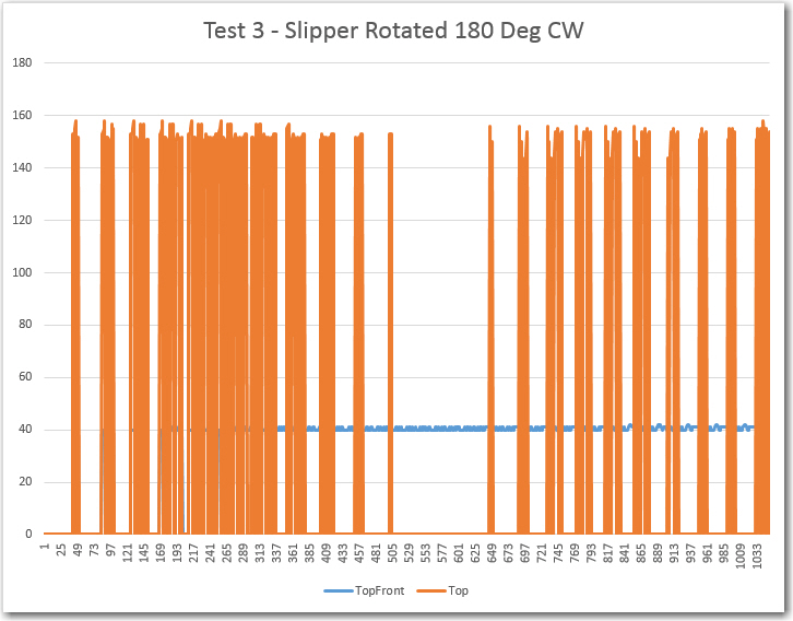
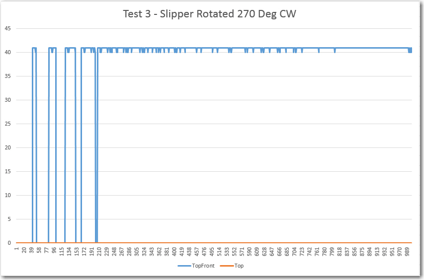
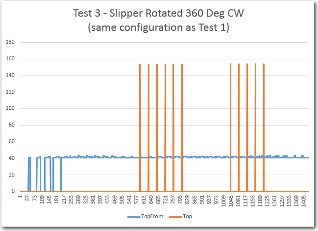
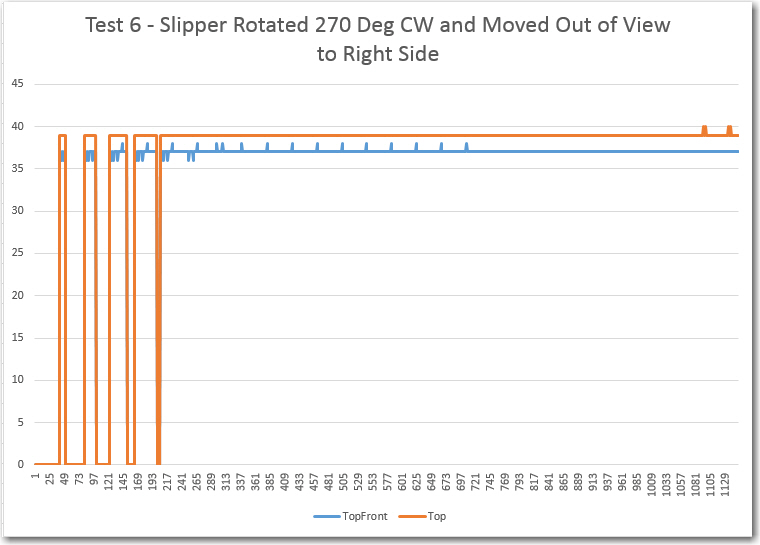
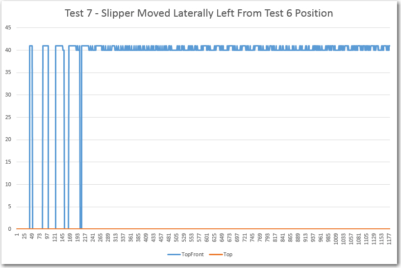
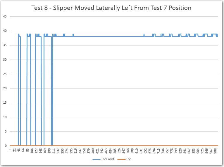
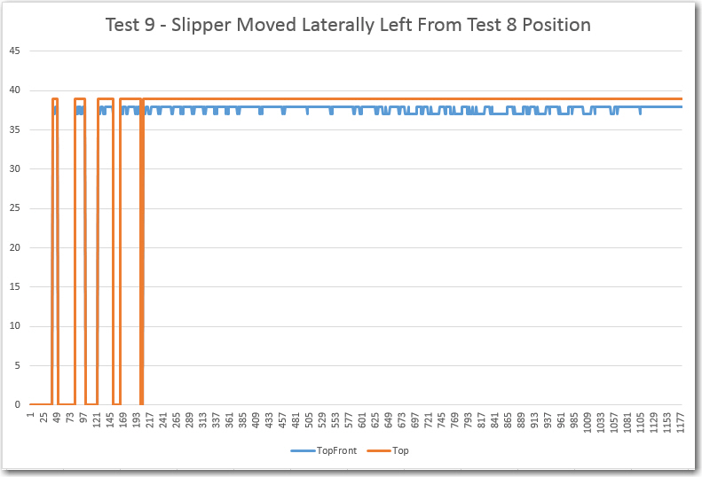
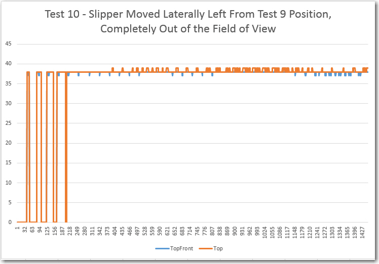
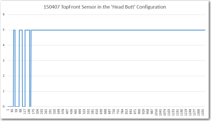
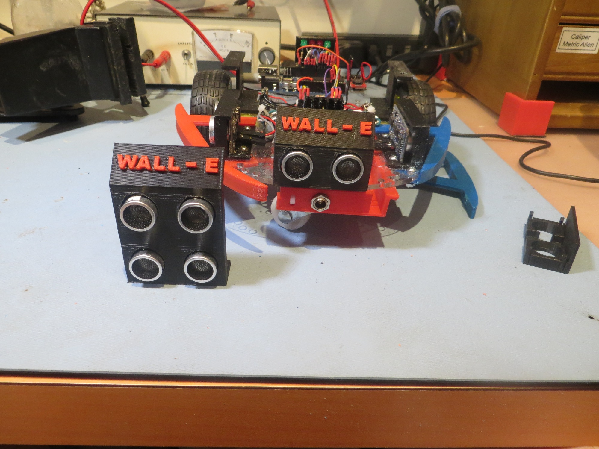
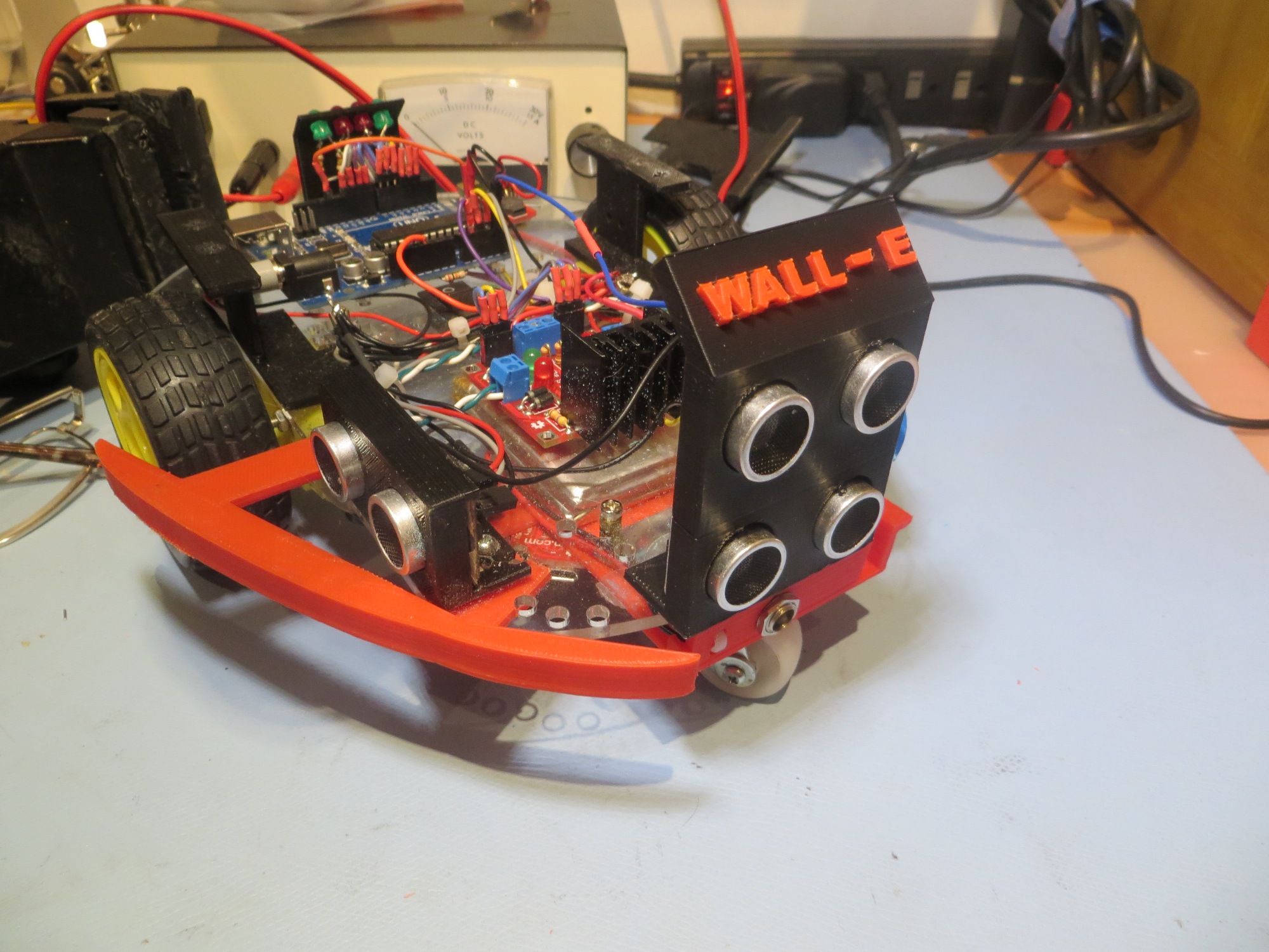
The only other potential clue in this whole mess is the way the sensor reading arrays are being handled.  The idea was that when a ‘stuck’ detection occurred, The arrays should be re-initialized in such a way that another ‘stuck’ detection could not occur until after another ARRAY_SIZE measurements have been collected.  The way I chose to do that was to simply place a large positive reading followed by a zero in the top of each of the 4 arrays, guaranteeing (I thought!) that those two adjacent values would prevent a ‘stuck’ detection for at least ARRAY_SIZE measurement cycles.  In order to verify that this ‘poison pill’ feature is actually working, I added the ‘PrintDistInfo()’ function from my PingTest project to Wall-E4 and ran it in debug mode on my bench.   Using this technique, I was able to watch (albeit slowly) the ‘poison pill’ values roll through my distance sensor value arrays.  So, it appears that is working fine, and the ‘stuck’ detection algorithm is working perfectly, too – in that it detects the ‘stuck’ condition as soon as it is able too (all the real distance information is pretty static with Wall-E sitting on the bench with no power to the motors)

So, the only conclusion i can reach with this information is that the MAX_DISTANCE_CM reduction from 200 to 100 significantly reduced measurement deviation, to the point where Wall-E was declaring ‘stuck’  even when he wasn’t.  This tracks with another observation – Wall-E seemed to declare ‘stuck’ just as the distance from one  or the other side sensors increased, like an open door or something like that.  Apparently this causes a ‘out of bounds’ (zero) return with a MAX_DISTANCE_CM of 100 more often than with 200.

So, what to do?  I can just use the differential distance readings between the front and top-front sensors, but while this should work for the slipper case where the front sensor is partially or totally obstructed, it won’t work for the coat rack or rug edge case where both front sensors are unobstructed.  It might  work to use a two dimensional test; if the two front sensors have close to the same readings but those readings don’t vary over time,  OR their readings differ significantly at any time, then declare ‘stuck’.  If I go this way, I’ll need to open up the front sensor max distance to something more than 200 cm (300-500?) so Wall-E won’t declare ‘stuck’ in an open hallway.  Since the side sensors would no longer be used for the determination, I could keep their max distances short – say 100 cm, which would allow me to shorten the post-ping delays for them a bit.

  • Change  MAX_DISTANCE_CM to 400 cm.  Use  MAX_DISTANCE_CM for the two front sensors and  MAX_DISTANCE_CM / 4  for the side sensors.
  • Change the ‘stuck’ detection algorithm to use only the front sensors, as discussed above
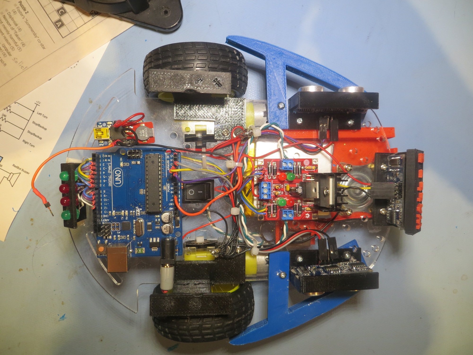
  • Remove  the  aRightDist and aLeftDist arrays.
  • Change the inter-ping delays.  It is generally a good idea to wait 20-25 msec between ping sensor triggers to avoid returns from one sensor being interpreted as returns by another sensor.  However, I believe it is OK  to have  no delay between the left and right ping sensors.  In order for ping energy from the left sensor to be interpreted as a return by the right sensor, that energy has to arrive at the right sensor  after the right sensor has been triggered, and  before the right sensor’s energy gets back.  If the delay from left to right sensor activation is more than about 25 msec, there’s no way the first criteria (arriving after the right sensor is triggered) can be met, so this is perfectly safe, if a bit wasteful of time.  However, if they are triggered together (no inter sensor delay), then there is no way the second criteria can be satisfied for any reasonable geometry, as the left sensor’s energy will always have farther to travel by 2 times the distance from the left sensor to the nearest object.  So, I believe it is safe to trigger the left and right sensors together, then delay 15-25 msec between the L/R pair and either the top-front or front, and then another 15-25 msec between the two  front sensors.

OK, so I made the changes described above, and Wall-E is  still  getting stuck, although less frequently than before.  In fact, there were a couple of times during the last set of field trials where it seemed that Wall-E was actually doing very well.  However:

  • The wall following performance is still mediocre at best, especially compared to where it was before I started adding inter ping sensor delays.
  • Wall-E still gets stuck and won’t declare ‘stuck’ for no apparent reason.  In one case he had his nose pressed firmly up against a solid surface, which should have produced stable readings from both front sensors, but apparently satisfied neither the max deviation nor top-front/front deviation difference criteria.   In another, both front sensors were unobstructed, and the nearest obstacle was only about 75 cm away – should have been a slam-dunk, but wasn’t.

At this point, I think the only way forward is to find a way to record what is actually happening with Wall-E during a period where it the ‘stuck’ criteria should be met, but nothing is happening.  My hope is that I can figure out how to use Arduino’s EEPROM to record data ‘on the fly’.

Stay tuned!

Frank


New ‘stuck’ Detection Scheme, Part V – Stealth Slipper Study

Posted 04/08/15

As I drifted off to sleep last night, it occurred to me that I had not really completed my study of ping sensor responses, as I did not yet fully understand what was happening with the ‘stealth slipper’ (aka the wife’s fuzzy slippers) case.  So, this morning I re-opened the Paynter indoor test range for some additional tests.  As shown below, I placed a slipper in various orientations in front of Wall-E’s dual front ping sensor setup, and took sensor data for each case.

Test 1: Slipper Head-on:

Slipper head-on with robot front

Slipper head-on with robot front

Test 1 results.  Note front sensor ping being completely absorbed, causing it to return zeroes

Test 1 results. Note front sensor ping being completely absorbed, causing it to return zeroes

Test 2: Slipper Rotated 90 Degrees CW:

Slipper turned 90 degrees  clockwise

Slipper turned 90 degrees clockwise

Slipper rotated 90 degrees CW.  Note lower ping sensor still completely blocked, but upper one is still OK

Slipper rotated 90 degrees CW. Note lower ping sensor still completely blocked, but upper one is still OK

Test 3: Slipper Rotated 180 Degrees CW:

Slipper turned 180 degrees clockwise

Slipper turned 180 degrees clockwise

150408_SlipperTest3Plot

This result is pretty interesting in that it looks like the front sensor gets confused by the open cavity presented by the slipper in this configuration, while the top-front sensor is nice and stable.  This is a very good justification for having both forward-looking sensors!

Test 4: Slipper Rotated 270 Degrees CW:


Slipper turned 270 degrees clockwise

Slipper turned 270 degrees clockwise

150408_SlipperTest4Plot

The plot shows that the lower (front) sensor is completely blocked,  (returning zeros), while the upper (top-front) sensor is completely clear, returning a nice, stable reading with a max deviation of just 1 cm.  Again, this plot is a great justification for having two forward-looking sensors.

Test 5: Slipper Rotated 360 Degrees CW:

Slipper rotated 360 degrees clockwise (same configuration as Test 1)

Slipper rotated 360 degrees clockwise (same configuration as Test 1)

150408_SlipperTest5Plot


This is the same configuration as Test 1, but with different results :-(.   I suspect the difference is due to the slipper being offset laterally one way or another, just enough to cause the spikes noted.  Another possibility is that there is occasionally just enough echo from the fuzzy slipper to make the sensor think there is something there, but at extreme range.  In any case, the top-forward sensor continues to provide a nice, stable response with minimum deviation.


Test 6 – 10  : Slipper Rotated 90  Degrees CW and Translated from Far Right to Far Left:

This series of configurations starts with the slipper in the 90 degree CW rotation position (similar to Test 2) but translated to the right. Then it is moved through three intermediate positions (Tests 7-9) to a position out of view to the left (Test 10).

First of 5 tests with the slipper moving laterally from right to left

First of 5 tests with the slipper moving laterally from right to left

150408_SlipperTest6Plot

Second of 5 lateral displacement tests, with the slipper moving from right to left

Second of 5 lateral displacement tests, with the slipper moving from right to left

150408_SlipperTest7Plot


The Test 6 position is apparently far enough to the right so that both the front and top-front sensors have a (mostly) clear view to the front, producing stable returns with a maximum deviation of just 1 cm for both.


Third of 5 lateral displacement tests, with the slipper moving from right to left

Third of 5 lateral displacement tests, with the slipper moving from right to left

150408_SlipperTest8Plot


Tests 7 and 8 show the same result – the front sensor is blocked (returning zeros) and the top-front sensor can still see, returning a stable result with a maximum deviation of 1 cm.


Fourth of 5 lateral displacement tests, with the slipper moving from right to left

Fourth of 5 lateral displacement tests, with the slipper moving from right to left

150408_SlipperTest9Plot

Last of 5 lateral displacement tests, with the slipper moving from right to left.  In this test, the slipper is all the way out of the field of view

Last of 5 lateral displacement tests, with the slipper moving from right to left. In this test, the slipper is all the way out of the field of view

Test 10 results.  Note both front and top-front sensors return nearly identical, stable results.

Test 10 results. Note both front and top-front sensors return nearly identical, stable results.

Tests 9 and 10 are also similar, clearly showing that both the front and top-front sensors can see the wall at around 37/38 cm, with a maximum deviation for both sensors of 1 cm.


Summary and Conclusions:

This post describes a set of measurements intended to explore the effect of my wife’s ‘stealth slippers’ on Wall-E’s forward sensor performance, in order to implement an effective algorithm for getting Wall-E ‘un-stuck’ when it runs up against a slipper during its travels through the house.  Ten separate tests were performed in a controlled environment, recording both the front and top-front sensor responses to various slipper configurations.

Based on the test results above, I think I can safely make the following conclusions:

  • The top-forward sensor can reliably ‘see over’ a slipper and reliably produces a stable response (the actual distance if there is an obstacle, or zero if there is nothing within 200 cm), with a maximum variation of 1-2 cm.
  • When  both sensors report similar distances, then it is almost certain there is no nearby blocking obstacle (aka ‘stealth slipper’).
  • When the top-front and top-front sensors report wildly different numbers, then it is highly probable that Wall-E has gotten stuck on a slipper (or other low-lying obstacle) and the ‘stuck’ algorithm should be triggered.
  • The SR-04 sensors and the NewPing driver library seem remarkably accurate and stable. All the problems experienced so far with ‘unreliable readings’ have been self-inflicted, mostly by not heeding the time separation requirements.

Frank


New ‘stuck’ Detection Scheme, Part IV

Posted 04/07/15

In my last post, I described the results from ping sensor testing in my ‘indoor acoustic testing range’, AKA ‘my office’. The results were plotted in a series of Excel charts. While these results did vividly illustrate why Wall-E was having so much trouble detecting the ‘stuck’ condition, they also raised a number of questions. In the previous post I listed a number of follow-on tests I thought I should perform, as follows:

  • Do the same experiment with the front ping sensors disabled, to eliminate the possibility of echo contamination between the front and left and/or right sensors.
  • Look at the front ping sensor response when Wall-E’s nose is pressed up against a wall.  This won’t normally be an issue, as Wall-E’s normal obstacle avoidance routine will make it stop and turn around when it gets within about 10 cm of an obstacle, but I have disabled that while trying to work out the ‘stuck’ detection issues. So, I need to understand just what is happening in this case.
  • Change the MAX_DISTANCE_CM parameter from 200 to 100.  It is clear to me from my lab ‘indoor test range’ experiments that 100 cm in each direction is more than enough to handle almost all situations in my house, and if this change eliminates the wild variations with no object in view, so much the better.

Do the same experiment with the front ping sensors disabled, to eliminate the possibility of echo contamination between the front and left and/or right sensors.

In this experiment I simply disconnected  the front and top-front ping sensors from the Arduino, and ran the same experiment as before.  I started with all 3 obstacles in place, removed the left obstacle after a few seconds, and then removed the right one (didn’t need to do anything with the front one).  This produced the following plot

Ping test with front ping sensors disconnected.  Note that both the left and right sensor data are 'clean' except for the obstacle/no obstacle transition period

Ping test with front ping sensors disconnected. Note that both the left and right sensor data are ‘clean’ except for the obstacle/no obstacle transition period

Note that both the left and right ping sensor data are very clean except during the brief period when the obstacle is being removed.  This result clearly shows that there is some external feedback happening between the front ping sensor and at least the left sensor.  I  thought I had been careful about spacing the sensor ping intervals in time to avoid just this possibility, but clearly I wasn’t as careful as I thought!.  Shortening the MAX_DISTANCE_CM parameter to 100 vs 200 might eliminate (or at least suppress) that problem, but I would really prefer to definitely prevent it entirely.  Looking at the code, I see the following commands for ping spacing in my ‘MoveUntilStuck()’ loop:

leftdistval = LeftPing.ping_cm();
delay(25); //added 04/04/15
rightdistval = RightPing.ping_cm();
delay(25); //added 04/04/15
frontdistval = FrontPing.ping_cm();
delay(25); //added 04/04/15
topfrontdistval = TopFrontPing.ping_cm(); //added 04/04/15

The ‘delay(25)’ should be more than adequate to prevent one set of pings from leaking into another sensor, but (now that I’m looking for it), I see that I didn’t put a ‘delay(25)’ after the TopFrontPing.ping_cm() call.  If the subsequent processing were fast enough (and I think it is), then the time between this call and the LeftPing.ping_cm() call could be very short – like just a few milliseconds.  This  could be the cause of the large variations  noted in the left sensor data after that obstacle was removed.  The absence of variation with the obstacle present could be due to the fact that the much narrower receive time window would be closed by the time the ping energy from the front sensors made it around the external geometry and back to the left sensor.

The way to definitively test this theory is to add the required ‘delay(25)’ to the code after the TopFrontPing.ping_cm() call and redo the test with all three sensors enabled.

Ping test with delay(25) added and with front ping  sensors re-enabled.

Ping test with delay(25) added and with front ping sensors re-enabled.

From the above plot it is clear that the left sensor data with its obstacle removed is still clean (or at least much cleaner).  The deviation for the period from item 1200 to item 2000 is only 3 cm, much smaller than the typical ‘stuck’ threshold of 5-10 cm.  The right sensor has a similar deviation (4 cm) for the period from 1800 to 2500.  However, the front sensor still shows extreme variation after its obstacle was removed, so there is still a problem somewhere.  This issue could be as simple as the effect of being very near the MAX_DISTANCE_CM distance from the nearest obstacle (the wall underneath my work surface).  To test this theory, I turned the robot around so it had a clear path of well over 200 cm to the nearest obstacle, and made a short run.

Maximum range testing for the TopFront ping sensor

Maximum range testing for the TopFront ping sensor

The test procedure that produced the above plot was to start with the obstacle placed at about 48″ (122 cm) from the sensor.  After a few seconds I moved it to 60″ (152 cm), then to 72″ (183 cm), and then I removed it entirely for a few seconds.  Next I moved it in small steps back and forth around the 200 cm (approx 78″) boundary to see if I could replicate the large variations observed in the previous trial with the front obstacle removed.  As the plot shows the front sensor (gray curve) produced quite clean data at each position, including producing a clean ‘zero’ reading when there was no object in view within 200 cm.  Also, I was able to produce a reasonable simulacrum of the large varations seen when the object is right on the 200 cm boundary.  Note that the large variations in the left side sensor readings (blue trace) is due to me walking by it in order to reposition the front obstacle, and of the large deviations in the front sensor readings are due to me moving the obstacle.  The large variations in the front sensor toward the end of the recording are due to the obstacle being placed right on the 200 cm boundary.

So, I think the testing in Part II and IV has completely answered the question of why Wall-E’s ‘stuck’ detection scheme was misfiring so badly in my field tests.  The culprit was cross-contamination between the front and left-side sensors due to the lack of proper time spacing between those two ping() calls.  In addition, I believe the data convinces me that there is no good reason to change the MAX_DISTANCE_CM parameter from its present value of 200 cm.  It is clear that all 3 (or 4) sensors can easily measure that far out with 1-2 cm repeatability, and a lower range limit would just increase the frequency of occurrence of  obstacles passing through the max range transition area.

One test remains – the Wall-E ‘head-butt’ configuration where Wall-E has his nose right up against an obstacle. This doesn’t  normally occur, as the  default obstacle avoidance procedure is to back up and turn around whenever an obstacle comes within about 10 cm of the forward sensor.  However, when I was field testing the ‘stuck’ detection scheme, I disabled the default obstacle avoidance routine, allowing Wall-E to get stuck by running directly into a forward obstacle (like a wall).  So, in the interests of completeness, I want to make sure I understand what that condition does to  the forward sensor data.  To test this, I placed Wall-E with its forward sensor bracket directly against a wall, just as if it had driven into it.  Then I recorded enough data to make a good determination of the effect.

Wall-E in the 'Head Butt' configuration

Wall-E in the ‘Head Butt’ configuration

Wall-E TopFront Sensor Response in the 'Head Butt' Configuration

Wall-E TopFront Sensor Response in the ‘Head Butt’ Configuration

As can be clearly seen in the above plot, Wall-E does quite nicely in the ‘Head Butt’ configuration, returning a constant 5 cm reading.  This is in error by at least 4 cm (not sure where the actual measurement center is on the transducer), but there’s no doubt that this configuration would easily meet the deviation threshold requirements for ‘stuck’ detection.

In summary, I now think I have a very good (if not quite complete) understanding of the salient characteristics of the SR-04 ping sensors, their interaction with the NewPing driver library, and their performance in multiple installations on the Wall-E robot.  I’m now convinced that the ‘stuck’ detection scheme will work quite nicely with a 200 cm MAX_DISTANCE_CM setting.  It’s  way too late tonight to do the required follow-up field testing, but I’m now very confident that when I do them, they’ll be successful.

Frank

New ‘stuck’ Detection Scheme, Part III

Posted 04/06/15

In the last episode of the ‘stuck’ detection saga, I added a second forward-looking ping sensor above the existing one, on the theory that this would help address  the ‘stealth slipper’ issue.  However, field trials with the new system didn’t really show much improvement – Wall-E still gotstuck and couldn’t seem to figure it out without help.

To try and clarify what was going on, I disabled the normal forward obstacle avoidance maneuver that is triggered whenever Wall-E gets within about 10cm of an object.  This caused the robot to run right into forward obstacles without stopping.  The idea was to see if the ‘stuck’ detection algorithm would take over and get Wall-E free.  As it turned out, the robot would simply sit there forever with its nose pushed firmly up against whatever it was stuck on.

Classic Wall-E 'Nose Plant' position

Classic Wall-E ‘Nose Plant’ position

The ‘stuck’ detection algorithm was designed to trigger when the variation in distance readings from the left, right, and top-forward sensors falls below a settable threshold, as  should be true whenever Wall-E gets stuck.  In the field trials, this seemed to be exactly what was happening, except Wall-E never figured it out.    After scratching my head about this for a while, I noticed that I could  sometimes  trigger Wall-E’s ‘stuck’ detection routine by placing a foot in the field of view of one of the side sensors, typically the one on the opposite side from the nearest wall, as shown below.

This sometimes triggered the 'stuck' detection routine

This sometimes triggered the ‘stuck’ detection routine

This technique wasn’t terribly consistent, but it did work enough times to make me think that I was on to something.   I began to think that the ‘offside’ sensor distance readings contain sufficient variability to defeat the ‘stuck’ detection algorithm, even though the geometry is completely static, and the sensors are  supposed to report 0 if the nearest obstacle is beyond the preset distance limit (200 cm in my case).

After trying various combinations in the field trials, I decided to try to set up a more rigorous testing environment.  So, I connected Wall-E to my PC using a longish USB cable and set him on the floor of my lab, in a position where all four ping sensors were clear of obstacles for at least 200 cm.   The use of the USB cable also allowed me to power the Arduino without powering the motors, thereby eliminating a set of variables.  Then I placed an acoustically solid obstacle at various distances away from the front sensor and watched what happened.

The Wall-E Indoor Acoustic Sensor Test Range

The Wall-E Indoor Acoustic Sensor Test Range

What I discovered was that Wall-E, when left alone with nothing in range of any ping sensor, will never declare itself stuck, even when it is clearly sitting still (motor drives disabled)!  However, if there is an object within range of  any sensor, then it will shortly detect the ‘stuck’ condition.

The clear implication of this observation is that the sensor response with nothing in view is not constant, but has sufficient variation to overwhelm  the ‘stuck’ detection algorithm.  This appears to be  contrary to the NewPing library specification, which states that the response to a ping where there is no object within the specified max detection range will be constant (zero, actually).  OTOH it is possible that my current 200 cm max range specification is too large, and what is happening is intermittent detection of objects that are nearly 200 cm away, and sometimes a zero is returned and sometimes not.

The only direct way to clear up the mystery is to look at the actual ping sensor data in the ‘no object in view’ case and see what is returned.  To do this I will probably need to create a specialized Arduino program to take the data and then report it.

So, I created a new Arduino sketch called ‘PingTest1’ (clever name, huh?) that simply reports the contents of the left, right, and top-front ping sensor  arrays  about once per second.  This data was then sucked into Excel and graphed.  Four different physical configurations were tested, in the following order:

  1. Obstacles at about 75 cm in view of all three sensors (Figure 1)
  2. Left obstacle removed (Figure 2)
  3. Left and right obstacles removed (Figure 3)
  4. All three obstacles removed (Figure 4)
Obstacles at about 75 cm From Left, Right, and Front Sensors

Obstacles at about 75 cm From Left, Right, and Front Sensors

Left Obstacle Removed

Left Obstacle Removed

Left and Right Obstacles Removed

Left and Right Obstacles Removed

All 3 Obstacles Removed

All 3 Obstacles Removed

This produced the overall plot shown below.  The first 200 or so data points show the process of replacing the initial zero state of the distance arrays with real values as they are acquired.  The left obstacle is removed at about item 1000, the right obstacle at about item 1700, and the front one at about 2800.

Overall plot of approximately 3600 sets of sensor readings

Overall plot of approximately 3600 sets of sensor readings

First 1000 or so points, showing the fill procedure and the response with all 3 obstacles present

First 1000 or so points, showing the fill procedure and the response with all 3 obstacles present

From about 800 to 1900, showing the responses with the left obstacle removed

From about 800 to 1900, showing the responses with the left obstacle removed

From 1800 or so to 2900, showing the Left and Right obstacles removed

From 1600 or so to 2900, showing the Left and Right obstacles removed

From about 1900 to 3600, showing the responses with all 3 obstacles removed.  Note the large variations returned by the top front ping sensor

From about 2600 to 3600, showing the responses with all 3 obstacles removed. Note the large variations returned by the top front ping sensor


My general impression after looking at this data was “What a mess!”.  I’ll never be able to detect a ‘stuck’ condition with all this variation, especially the HUGE (over 50 cm) high-frequency variation  in the top front distance readings, not to mention the less frequent (but no less disastrous) rail-to-rail excursions from nearly 200 to 0 and back again.  However, there are some features about this data that make me think I’m not completely out of luck.  The response with all three obstacles present is quite clean – with less than 2 cm variation on all three channels.  I believe this section explains why I was occasionally able to get Wall-E to detect the ‘stuck’ condition if I placed an obstacle (my foot) in view of whichever side sensor was ‘staring off into space’.  It also explains why I had to use  both  feet when both the left and right sensors had no nearby wall features in view.  By inserting an obstacle into the sensors’ view, I was moving the configuration from the right side of the overall plot above, with all its ugly variation, to the left side where the data is nice and clean with very little variation over time.

However, I’m at a complete loss to explain the large variation in the left sensor distance measurements with the left obstacle removed.   I can rationalize the mean number of about 120 cm as coming from items under my work surface on the left side, but all that stuff is  static – no movement at all!  When the right obstacle is removed, it’s readings jump from about 75 to about 175 cm, consistent with the distance to my bookcase on that side,  and the readings continue to be quite clean – less than 4 cm variation across the entire period.  Then there is the double (or is it triple) mystery of what happens when the front obstacle is removed.  The front distance reading goes from about 75 to about the same average as the right sensor, but the variation is HUGE – 50 cm or more!  And just to add to the mystery pile, the variations in the left sensor distance readings largely disappear – how can that possibly happen?  It actually looks like there is some relationship between the removal of the front obstacle and the disappearance of the variation from left sensor readings – how can that be?  Is there some external feedback between the front and left sensors that isn’t present between the front and right sensors?  Could the ping timing be such that a ping is emitted from the front sensor, bounces off the front obstacle and then some objects in the field of view of the left sensor, arriving at the left sensor just in time to look like a valid echo?  I think I’m getting a headache! ;-).

Although this data raised as many questions as it answered, it is definitely a step in the right direction.  Now I need to repeat this experiment with some modifications, as follows:

  • Do the same experiment with the front ping sensors disabled, to eliminate the possibility of echo contamination between the front and left and/or right sensors.
  • Look at the front ping sensor response when Wall-E’s nose is pressed up against a wall.  This won’t normally be an issue, as Wall-E’s normal obstacle avoidance routine will make it stop and turn around when it gets within about 10 cm of an obstacle, but I have disabled that while trying to work out the ‘stuck’ detection issues. So, I need to understand just what is happening in this case.
  • Change the MAX_DISTANCE_CM parameter from 200 to 100.  It is clear to me from my lab ‘indoor test range’ experiments that 100 cm in each direction is more than enough to handle almost all situations in my house, and if this change eliminates the wild variations with no object in view, so much the better.

More to come,

Frank


New ‘stuck’ Detection Scheme, Part II

As described in the previous post on this topic, my plan was to use about 1 second’s worth of stored data to (hopefully) detect the ‘stuck’ condition, where Wall-E has managed to get himself stuck without triggering the normal obstacle avoidance routine.  As I mentioned before, this happens when it hits an obstacle that is too low to register on the front-facing ping sensor (like the legs on our coat rack), or too acoustically soft to return a good distance reading (like my wife’s slippers).

So, I implemented three byte arrays, each K bytes long to hold 1-2  second’s worth of data (K was set to 50 initially).  Each array is loaded from the ‘top’ (position K-1), and older data is shifted down to make room. The oldest reading gets dumped off the bottom into the bit bucket.  Then, at each pass through the movement loop, the function IsStuck() is called to assess the presence or absence of the ‘stuck’ condition.  For each array, the maximum and minimum readings are acquired, and then they are subtracted to give  the maximum distance deviation

for that sensor over that period.  If the maximum distance deviation for all three sensors is below some arbitrary (initially 5  cm) limit, then the ‘stuck’ condition is declared, and the movement loop is terminated, causing a return the main program loop.  This in turn causes the ‘RecoverFromStuck’ routine, (which does the backup-and-turn trick) to run.

I was a bit worried about the amount of RAM consumed by the arrays, but it turned out to be negligible.  I was also worried about the amount of time it would take to manage the arrays and make the deviation computations, but this too turned out to be a non-problem.

However, what  did turn out to be a problem is that the darned thing didn’t work!  Well, the coding was OK, and the algorithm worked just the way I had hoped, but Wall-E was still getting hung up on the coat rack and on the wife’s slippers.  Wall-E would occasionally recover from the coat rack, but never  from the slipper trap.  Apparently the fuzz on the outside of the slipper makes them pretty much invisible at the ultrasonic frequency used by the ping sensors.  I played around with the array length and distance deviation threshold parameters, but if I tightened everything down to the point where Wall-E would reliably un-stick itself, it would also reliably trigger the ‘stuck’ condition repeatedly during a normal wall-following run.  This led to a condition where Wall-E was going backwards more often than it was going forward; amusing for a while, but  definitely  not what I had in mind!

Wall-E's nemesis - the wife's slippers

Wall-E’s nemesis – the wife’s stealth slippers

So, Wall-E was stuck on slippers, and I was stuck for a way around/over/through the problem.  Often when I come across a seemingly insurmountable problem, I beat my head against it for way too long (I  am an engineer, after all).  However, I have also learned that if I drop the issue for a while, I often come up with an answer (or at least another approach) ‘out of the blue’ while doing something entirely unrelated.

In this case I was driving to a bridge game at the local club and musing idly about Wall-E’s slipper fetish.  I had done some fairly careful bench tests in debug mode and had discovered that the real issue wasn’t that the slippers were acoustically invisible, it was that they  weren’t quite invisible, and the front ping sensor distance readings varied from 7 cm to infinity (infinity here being 200 cm).  This is what was causing the ‘stuck’ detection scheme to fail, as there was enough variability over the 1-2 second time frame so that the detection threshold was never met.  So, I’m thinking about this, and it suddenly occurred to me that the solution was to add a second forward-looking ping sensor  above the current one, so that when Wall-E snuggled up against one of my wife’s slippers, the top sensor would still have a clear line of sight (and would hopefully either report a real distance to the next obstacle or report 0 for ‘clear’).  In fact, I might even be able to exploit the variability of the bottom sensor in ‘slipper fetish’ mode by comparing the top and bottom sensor readings.  A ‘clear’ (or constant real distance) reading from the top sensor and a varying one from the bottom sensor might be a definitive ‘stuck on a slipper’ determinant.

And, because I ‘have the (3D printing) technology’, I was able to modify the front sensor bracket design to add another ping sensor location above the existing one, and print it out on my PowerSpec 3D Pro printer.  So, within a day of my drive-time ‘aha’, I had a new dual ping sensor bracket installed on Wall-E, and the second sensor wired into a spare analog input on the Arduino board.  Next I’ll have to add a 4th array to the setup, but coding  should be more or less copy and paste.  I will have to figure out whether or not I can simply compare the top & bottom sensor data to determine the’stuck on a slipper’ condition, or have to include data from the left/right ping sensors as well, but I’m very optimistic that this is a winner!

New dual ping sensor bracket next to existing single sensor bracket

New dual ping sensor bracket next to existing single sensor bracket

New dual ping sensor bracket mounted and wired up

New dual ping sensor bracket mounted and wired up

Baby Gets a New Bumper, Part II

Posted 04/04/2015

In my ‘Baby Gets a New Bumper’ I described my efforts to build a bumper for the robot that would defeat my robot’s tendency to hug chair legs.  In that post I described two bumper versions, the second of which did a credible, but not perfect, job of eliminating ‘chair leg love’.

In a subsequent Skype session with my grandson, he suggested that the front end of the bumper could be extended and curved slightly to eliminate the current small (but not zero) flat spot that still allows Wall-E to occasionally be successful in wrapping himself around a chair leg.  So, with me watching from Ohio via screen sharing, Danny in Missouri pulled up the shared bumper design in TinkerCad and went through a number of quick iterations, resulting in a much improved design.  I then downloaded this design to my PC back here in Ohio, printed it out on my PowerSpec PRO 3D printer, and installed it on Wall-E.  Total time from Skype session to printed part on the robot – about 12 hours (it would have  been faster, but I went off and played bridge for 3-4 hours).

Top view of Baby's new bumpers, Version 2

Top view of Baby’s new bumpers, Version 2

Getting ready to replace the right V2 bumper with V3

Getting ready to replace the right V2 bumper with V3

After replacing the V2 bumper with Version 3

After replacing the V2 bumper with Version 3

Right side is V3, Left is V2

Right side is V3, Left is V2

After getting the V3 bumper installed on Wall-E’s right side, it was immediately clear that the V3 bumper was better, but could also stand to be improved slightly (having a 3D printer and design tools like TinkerCad, not to mention a willing grandson, makes incremental improvement cheap and easy).  If the added section were rotated just slightly inboard, it would very nearly mate with the existing front ping sensor bracket and form a seamless slide surface when Wall-E next encounters a chair leg.  Just eyeballing, the required angle looked to be about 10-15 degrees – but I don’t need  to eyeball- I have the technology! ;-).  Anyway, I sucked the below image into Visio and used it’s dimensioning tools to measure the angle.  Turned out my  eyeball was pretty close – about 10 degrees should do the trick  (along with a length reduction of 5-10mm).


V3 Bumper Additional Angle Dimension

V3 Bumper Additional Angle Dimension

Frank