Posted 04/26/15
In my last post I showed there was a lot of variation in the data from Wall-E’s ping sensors – a lot more than I thought there should be. It was apparent from this run that my hopes for ‘stuck’ detection using variation (or lack there of) of distance readings from one or more sensors were futile – it just wasn’t going to work.
At the end of the last post, I postulated that maybe, just maybe, I was causing some of these problems by restricting the front sensor max distance to 250 cm. It was possible (so I thought) that opening up the max distance to 400 cm might clean up the data and make it usable. I also hatched a theory that maybe motor or movement-related vibration was screwing up the sensor data somehow, so I ran some tests designed to investigate that possibility as well.
So, I revised Wall-E’s code to bump the front sensor max distances to 400 cm and made a couple of runs in my test hallway (where the evil stealth slippers like to lurk), to test this idea. The code adjustment had a bit of a ripple effect, because up til now I had been storing the distance data as single bytes (so could store a distance reading of 0-255 cm), and storing 2-byte ints was going to take some changes. Fortunately a recently released update to the EEPROM library provide the put() and get() methods for just this purpose, so I was able to make the changes without a whole lot of trouble.
Results:
First, I ran a number of tests with the front sensor max distance still set at 255 so I could stay with the single-byte storage system, with and without the motors engaged, and with and without mechanically induced vibration (tapping vigorously on the side of the robot chassis) while moving it toward and away from my bench wall.
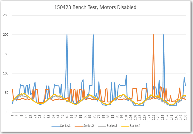
Test bench run with motors disabled, without any external tapping
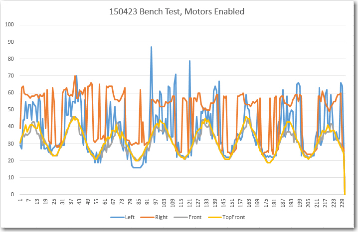
Test bench run with motors enabled, but no external tapping
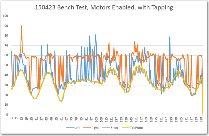
Test bench run, motors enabled, with external tapping
From these runs, it is clear to see that having the motors engaged and/or having an external disturbance does not significantly affect the sensor data quality.
Next, I enabled 2-byte EEPROM storage and a 400 cm max distance for the two front sensors. Then I did a bench test to validate that EEPROM storage/retrieval was being done properly, and then ran another field test in the ‘slipper’ hallway.
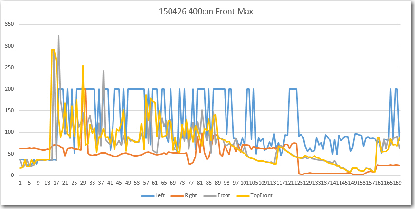
Field test with all sensors and motors enabled, 400 cm max distance on front sensors
The front and top-front sensor data still looks very crappy, until Wall-E gets within about 100 cm of the far wall, where it starts to look much better. From this it is clear that opening up the front max distance from 255 to 400 cm did absolutely nothing to improve the situation. Meanwhile, the offside side sensor readings are all over the place.
So, I have eliminated motor noise, mechanical vibration, and inappropriate max distance settings as the cause of the problems evident in the data. After thinking about this for a while, I came to the conclusion that either there was still some intra-sensor interference, and/or the hallway itself was exhibiting multipath behavior. To test both these ideas, I disabled the motors and all but the top-front sensor, and ran a series of 4 tests, culminating in a run in the ‘slipper’ hallway where I moved the robot by hand, approximating the somewhat wobbly path Wall-E normally takes. The results are shown below. In the first two tests I moved the robot toward and away from my test wall a number of times, resulting in a sinusoidal plot. In the two long range tests, I started approximately 400 cm away from the wall, moved close, and then away again, back to approximately 400 cm.
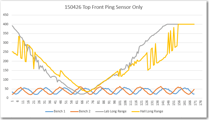
Test run in my lab and in the ‘slipper’ hall, top front sensor only (400 cm max distance).
The first two tests (‘Bench 1’ and ‘Bench 2’) validated that clean data could be acquired, and the ‘Lab Long Range’ test validated that the ping sensor can indeed be used out to 400 cm (4 meters). However, when the field test was run, significant variation was noted in the 150-350 cm range, and there doesn’t seem to be any good explanation for this other than multipath. And, to make matters worse, if one sensor is exhibiting multipath effects, it’s a sure bet that they all are, meaning the possibility (probability?) of multiple first, second, and third-order intra-sensor interference behavior.
After this last series of tests, I’m pretty well convinced that the use of multiple ping sensors for navigation in confined areas with multiple ‘acoustically hard’ walls is not going to work. I can probably still use them for left/right wall-following, but not for front distance sensing, and certainly not for ‘stuck’ detection.
So, what to do? Well, back to Google, of course! I spent some quality time on the web, and came up with some possibilities:
- The Centeye Stonyman Vision Chip and a laser diode. This is a very cool setup that would be perfect for my needs. Very small, very light, very elegant, and (hopefully) very cheap laser range finder – see https://www.youtube.com/watch?v=SYZVOF4ERHQ. There is only one thing wrong about this solution – it’s no longer available! :-(.
- The ‘Lidar Lite’ laser range finder component available from Trossen Robotics (http://www.trossenrobotics.com/lidar-lite). This is a complete, self-contained LIDAR kit, and it isn’t too big/heavy, or too expensive (there might be some argument about that second claim, but what the heck).
- The Pixy CMUCam, also available from Trossen (http://www.trossenrobotics.com/pixy-cmucam5). This isn’t quite as self-contained as it needs a separate laser and some additional programming smarts, but it might be a better fit for my application.
So, I ordered the LIDAR-lite and the CmuCAM products from Trossen, and they will hopefully be here in a week or so. Maybe then I can make some progress on helping Wall-E defeat his nemesis – the evil stealth slippers!
Stay tuned…
Frank
Pingback: End of the Road for Wall-E's Spinning LIDAR System :-( - Paynter's Palace
Pingback: Wall-E goes back to basics; Ping sensors and fixed forward-facing LIDAR - Paynter's Palace