Monthly Archives: March 2015

New ‘stuck’ Detection Scheme

Posted 04/01/2015 (not an April fool’s joke!)

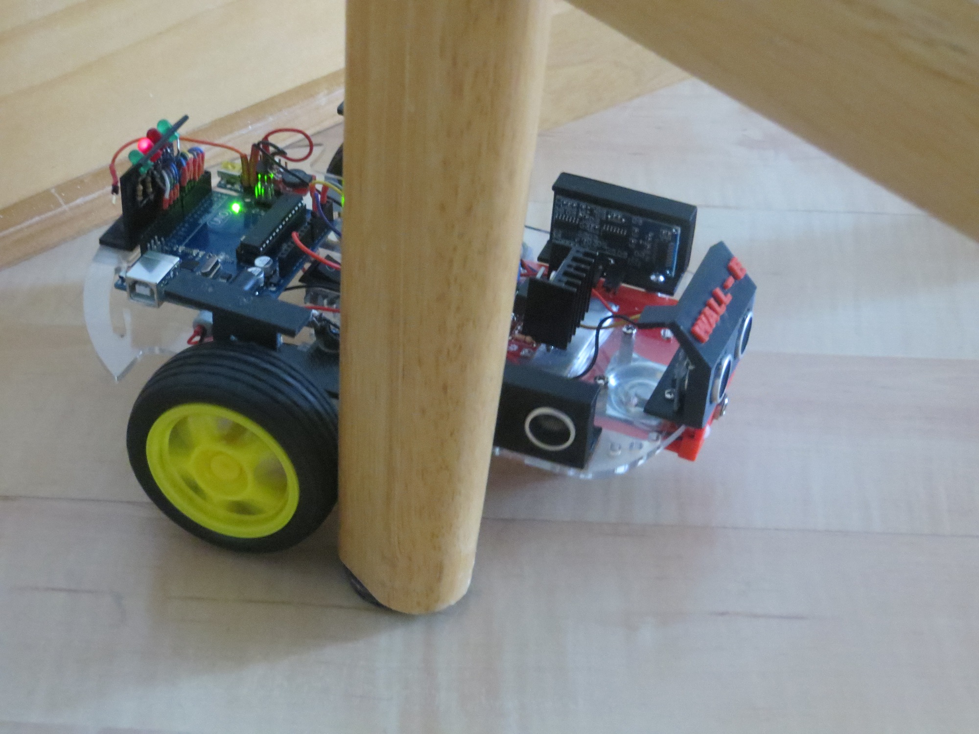
As I mentioned in my last post (Baby Gets a New Bumper) one of the outstanding issues with the robot is that it still gets stuck when it runs into something that is too low (like the feet of our coat rack or my wife’s slippers) to trigger the front sensor obstacle avoidance routine.  It then sits there, spinning it’s wheels fruitlessly, forever (or until someone takes pity on it and waves a foot in front of its front ping sensor).

The current obstacle detection  scheme is simply to monitor the front ping sensor distance readings and trigger the avoidance routine whenever the front distance falls below a set threshold.   Unfortunately there are some configurations like the ones mentioned above where this detection scheme fails.

So, the idea is to enhance this with an algorithm that detects the situation where the wheels are still engaged, but the robot isn’t moving.  So, how to detect “isn’t moving”?  If the robot isn’t moving, then subsequent distances reported by  any of the ping sensors will be the same, so that might work.  I actually used this algorithm initially for obstacle detection avoidance by comparing adjacent front ping sensor distance measurements. The idea was that if adjacent measurements matched, the robot was stuck.  However, I soon found at least two significant issues with this algorithm:

  • Ping sensors report a distance of zero whenever the actual distance is beyond the max detection range (set to 200 cm for my robot), so the obstacle detection scheme would trigger when there was nothing ahead at all.
  • It is quite possible for the reported distance to change 1 or 2 units either way, just due to round-off/truncation errors, so just comparing two adjacent measurements will be error-prone.

I can address the first of the issues above by using all three sensors, on the theory that the robot can’t be 200 cm from all three sensors at the same time (and if it  is, it needs to go somewhere else anyway!).  Unfortunately, this will require three times the work, but oh well ;-).

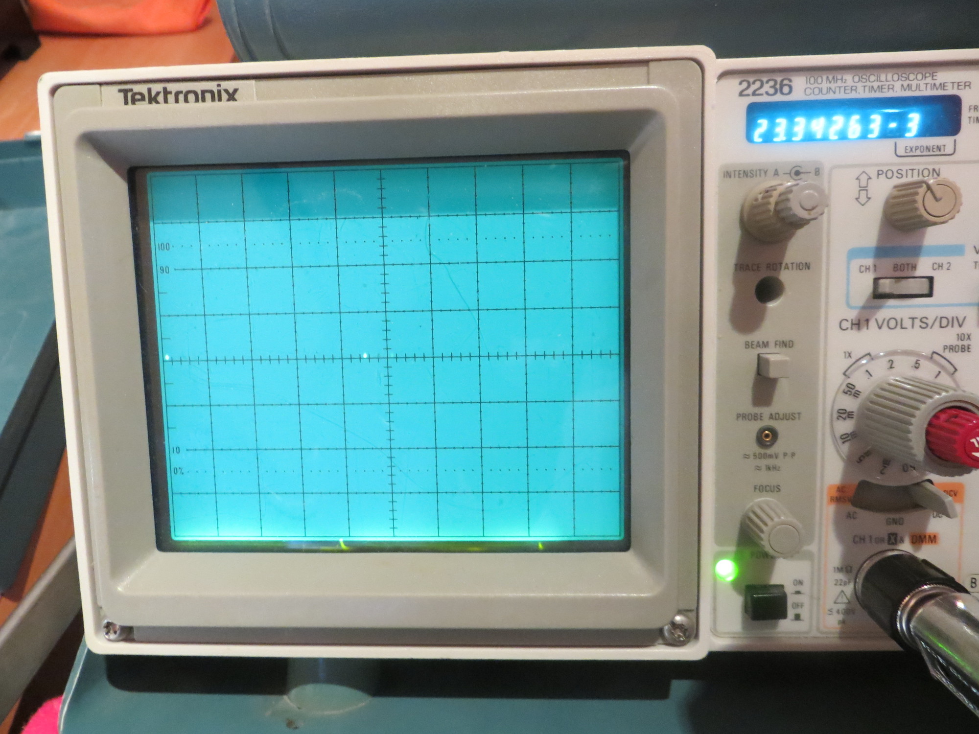
The second issue can be addressed with some sort of filtering/averaging scheme, which pretty much by definition implies some sort of multi-reading state memory and associated management code for each of the three sensors.  Fortunately my recent timing study revealed that the time required for the current movement/detection/movement code is insignificant compared to the delays inherent in the ping sensors themselves, so the additional time required to implement a more sophisticated ‘stuck’ detection scheme shouldn’t be a problem.

So, what about ‘stuck’ detection and filtering?  Assume we want to detect the ‘stuck’ condition within a few seconds of its occurrence (say 5?), and that each sensor is reporting about 20-50 readings per second.  So, 5 seconds worth of readings at 50 readings/sec is 250 readings.  Times 3 sensors is 750 readings, assuming I want to store the entire 5 seconds for all three sensors.

750 readings means 750 short integers (the distance range is 0-200 cm, which I should be able to store in an 8-bit unsigned short int), which should translate to just 750 bytes in RAM.  The Arduino Uno I’m using has 2048 bytes of RAM, of which I am currently using only 246 bytes.  So, I should have plenty of RAM space, assuming nothing in my code makes the stack grow too much.

Another way to skin the cat might be to just store the 5 second running average differential for each sensor, on the theory that the average differential would be some non-zero value while the robot is actually moving, but would trend to zero if it grinds to a halt somewhere.  Have to think about how I would actually implement that…..

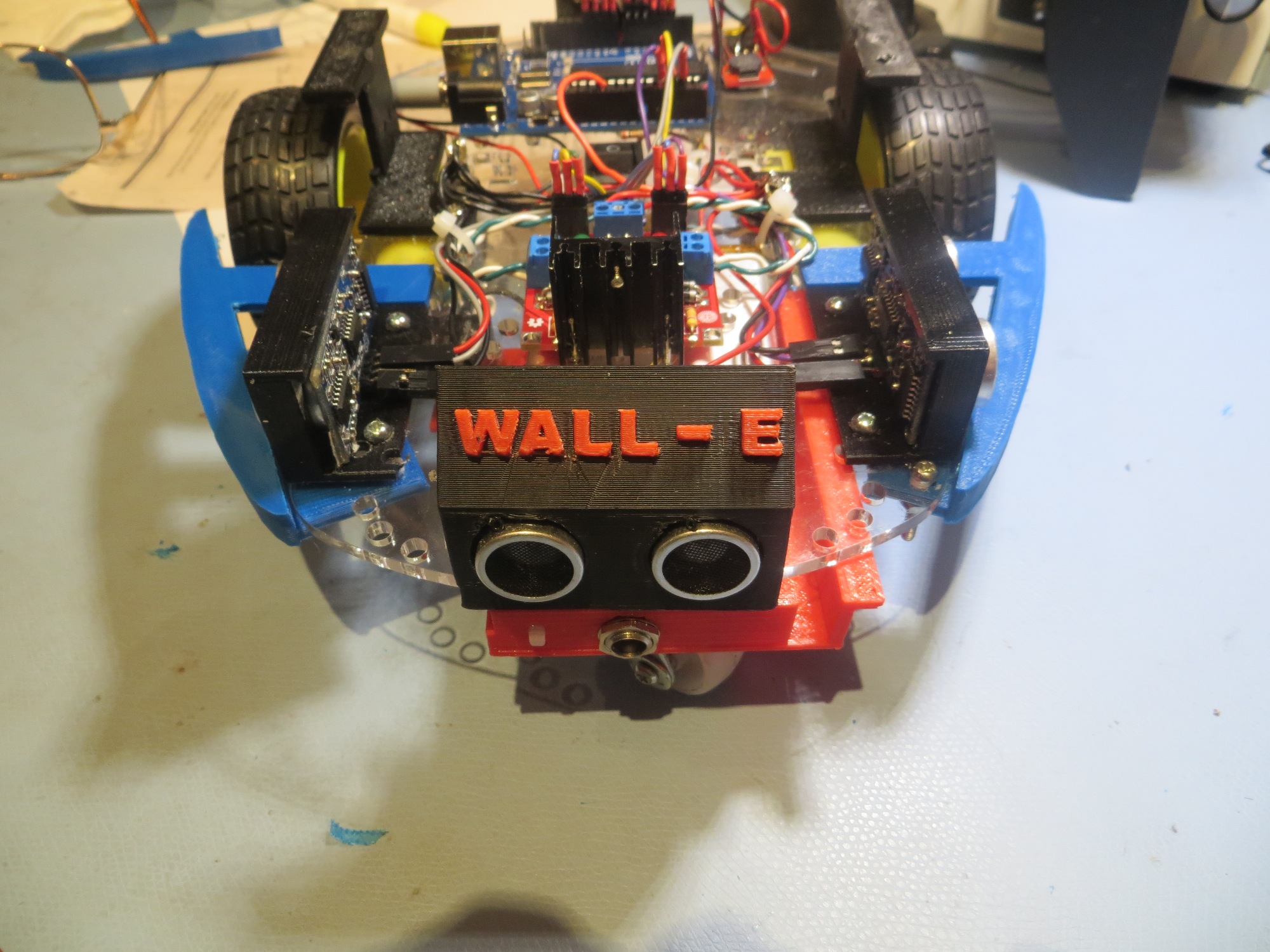
The central problem here is how to differentiate the ‘stuck’ condition from one where the robot is following a wall as normal, with no other wall or forward obstacle within range, or no forward obstacle but the ‘other’ wall is a constant distance away (a hallway, for example).  In both of these cases, all three ping sensors could, conceivably, report constant values (distance to left wall, distance to right wall, distance to forward obstacle).  IOW, holding a constant position with respect to both walls and having no forward obstacle would be indistinguishable from the ‘stuck’ condition.  The good news here is that even the best that Wall-E can do in terms of wall following involves a lot of back-and-forth ‘hunting’ movements, so there should be enough  short term variation in the left/right distances to distinguish active wall following from the ‘stuck’ state.  The bad news is that since the variation is cyclic, it is possible to select a period such that the short term variation gets aliased (or averaged) out – resulting in false positives.

Looking at the most recent video  of Wall-E in action (see below), it appears the ‘hunting’ motion has a period of  about 1 second, which would indicate the best time frame for distinguishing ‘stuck’ from ‘active’.  So, if I store measurements for about 1 second (i.e. about 20 – 50 measurements) from all three sensors, then the ‘active’ condition should show a full cycle of ‘hunting’ behavior from the left and/or right sensors, while the ‘stuck’ condition should have little/no variation across that time frame.  The forward sensor won’t show the ‘hunting’ behavior in ‘active’ mode, but it  should show either 0 (no obstacle within range) or a constantly declining value as an obstacle is approached.  For the forward sensor, there is no way to distinguish  the ‘stuck’ condition from the ‘active’ condition with no obstacle in range- oh well.

So, I think I’m getting a feel for the algorithm.  Set up an array of distance readings for the left, right and front sensors sufficient to hold about one second of readings each.  Each time through the movement loop, calculate the max deviation from one end of each  array to the other.  If the deviation for all three  arrays is below some threshold, declare the ‘stuck’ condition.

Next up – implementation and testing.

Frank


Baby Gets a New Bumper

Posted 03/30/15:

Now that the robot is starting to achieve real wall following more times than not, I’ve decided to address a serious robot  personality issue; my robot  loves chair legs!  If Wall-E gets within a meter or so of any chair in the house, it immediately hugs one leg between one side or the other of the chassis and that side’s wheel.  This causes the robot to go around and around the chair leg (or just spin it’s wheels in place), basically forever.  As you might understand, this is less than optimal performance from my point of view, regardless of Wall-E’s obsession with chair legs.

So, I’ve decided that Wall-E needs a bumper or fairing to keep chair legs from getting caught between the chassis and a wheel, as shown in the following photos and video.

Wall-E stuck on a chair leg.  Note the blurring of the wheel spokes as Wall-E churns away

Wall-E stuck on a chair leg. Note the blurring of the wheel spokes as Wall-E churns away to no effect!

So, after some quality time in  TinkerCad (and one failed version), I came up with a bumper design that doesn’t interfere with the current left/right ping sensor mounting, and seems to keep Wall-E from getting stuck on chair legs.  The photos below show the right side bumper – the left side is a simple mirror image.

Right Bumper1 Right Bumper2 Right Bumper3 Right Bumper4


Front oblique view of Baby's new bumpers

Front oblique view of Baby’s new bumpers

Top view of Baby's new bumpers

Top view of Baby’s new bumpers

At this point, Wall-E is starting to mature as an autonomous wall-following robot.  There are still at least two significant problems that need to be addressed

  • Wall-E still gets stuck – even with the new bumpers.  Not as often, but still…  I think I’ll need to develop a secondary ‘stuck state’ detection algorithm, maybe based on all three (left/right/forward) sensor distances remaining fixed for some period of time.
  • The little plastic castering nose wheel collects lint and cat fur like crazy, and soon has enough stuff wound around its axle to make it more of a castering skid than a wheel.  I don’t really have any good ideas about addressing this, short of replacing it with something else entirely.  That will be a major PITA, as I built the charging platform  around the nose wheel mount.

Stay tuned!

Frank


It’s All in the Timing

Posted 03/28/15

In my last post I described a change to the wall-following algorithm for Wall-E.  However, when I tried this for real, I didn’t get the expected performance gains.  In fact, it looked like performance had degraded rather than improved! ;-(.

So, I started thinking – again – about how to determine what’s really going on in the ping timing loop for Wall-E.  I have a time check using the Arduino  millisec() function that, supposedly, spaces pings at least 10 mSec apart.  I can see from the left/right LED activity that the loop is executing at least several times/sec, but I can’t be sure *how many* times per second – could be happening too quickly and I’m still getting ping confusion, or it could be happening too slowly and I’m wasting time.  As an experiment at one point I changed the minimum ping interval from 10 to 100 mSec, and the performance degraded dramatically and the left/right LED activity was also much slower, but again with no real numbers it’s hard to make an assessment.

So, today I dragged out my trusty Tektronix 2236 O’scope and looked directly at the ping timing for one of my three (left/right/front) ping sensors.  As shown in the video below, the actual ping time spacing was about 37 mSec (shown by the digital period timer at the upper right of the scope screen) rather than the 10 mSec programmed into the code.  I believe this means that the ping occurs every time through the Update loop, but it  other processes were extending the overall time required by the loop


So, I started commenting out pieces of the update loop to see if I could understand where the ‘tall poles’ (if any) are in the program.  First I commented out the code that manages the left/right ‘turn signal’ LEDs on the back of the robot, thinking maybe that was chewing up a lot of time.


10 msec loop timing, turn signal LEDs commented out

10 msec loop timing, turn signal LEDs commented out

This did reduce the loop time a bit, but nowhere near what I was expecting.  Finally, I had  everything commented out except the ping sensors themselves, and I was still getting some pretty big (and sometimes varying) numbers for the loop time – what was going on?

Finally, after a  lot of research into the NewPing library I was using, I came up with the answer.  The NewPing constructor for each sensor takes  a MAX_DISTANCE_CM  argument, and uses this number to cut off the ping receive routine after enough time has elapsed for the ping to get out to that distance and return, instead of waiting for up to one second for an echo to arrive.  For the 200 cm (2 meter) max distance I had specified, this number is about 12 msec (4 meter round trip time  divided by  334 m/sec speed of sound in air).  The actual delay I was seeing was about 17-18 msec max delay  per sensor.  Since on average, two of the three sensors (left/right/front) would not have anything within range, that meant that the minimum loop time would be around 35 msec + actual round-trip delay from the ‘active’ sensor.  I verified this by physically disconnecting all three sensors from the UNO and measuring the ping-ping interval of one of the three.  The result, as shown in the photo below, is very close to 3 * 18 = 54 msec.

150328_NoPingsNoLEDs

Leaving the ping sensors all disconnected (max ping delay) I then re-enabled all the rest of the processing (motor speed update, turn signals, etc).  The result was less than 1 msec longer, indicating that all the rest of the processing takes an insignificant amount of time; its all down to the ping delays.

As an experiment, I commented out all the ping sensor stuff, and added a line or two to manually generate a ‘ping’ trigger on one of the ping sensor trigger lines – thus simulating the use of a ping sensor, but without the issue of the echo delay.  When I did this, I got a ‘ping’ interval of almost exactly 10 msec – i.e. the programmed  MIN_PING_INTERVAL_MSEC.  Changing  MIN_PING_INTERVAL_MSEC to 5 msec resulted in an interval of almost exactly 5 msec.

So, now I think I have (finally!) a good handle on the loop timing issues for the robot – the ping sensors themselves and their related (and unavoidable) max_distance delays are by far the tallest  poles in the tent.  All of the rest of the processing done in the normal wall-following loop, including all the turn signal stuff, takes less than 1% of the total loop time.

The good news is that all the worrying I was doing about the impacts of more sophisticated tracking  algorithms was misplaced – I can do  LOTS of math and it won’t materially affect the total loop time!

The bad news is that my idea of  incorporating a second pair of left/right ping sensors angled at 45 degrees left and right of forward would probably result in a significant degradation of performance, just due to the unavoidable addition of  at least  20 msec to the total loop.  The only possible way to beat the max_ping_delay rap would be to go with NewPing’s timer-based functions that don’t block waiting for an echo.  This might be a way to accommodate  multiple left & right ping sensors, but it would come at the cost of  a lot of additional complexity.

Frank


Another Try at Wall-following Adjustments

Posted 3/25/2015

After a very enjoyable time with my grandson and his family (see  or this) , plus a not-so-enjoyable bout with the flu, it’s time to once again visit Wall-E’s wall following performance.

In the last post I moved the left and right ping sensors from their previous position well forward of the drive wheels to a position right over the axis of rotation, thinking that might allow for smoother wall-following.  What I found instead was that performance was severely degraded, to the point where Wall-E was more a wall-banging robot than a wall-following one ;-).

So, back  to the drawing board.  With the sensors themselves restored to their former positions, I decided to take another look at the wheel speed adjustment algorithm.  Wheel speed values range from 0 to 255, with 0 being stopped and 255 being full motor speed.  Currently, I start both motors at half speed (128) and then adjust the left/right motor speeds in a complementary fashion to achieve wall following.  When the current ping distance is less than the previous one, I speed up the inside motor and slow down the outside motor by the same fixed amount – 50 –  empirically derived  from a number of runs with different values.

This fixed adjustment or ‘tweak’ value of 50 is HUGE, especially when you consider that it is added to one motor speed value and subtracted from the other; this is effectively 50%  of the total range available to either motor.  This is clearly why Wall-E’s wall-following performance looks so jerky – it works, but it looks like he’s forever in danger of going out of control (which does happen on occasion).  However, on the plus side, it means that Wall-E does OK about negotiating corners, as it only takes two adjustment steps to get to an almost stopped wheel on one side and an almost full speed wheel on the other.

So, what I’m after is a more measured (pun intended) approach, where the ‘tweak’ value isn’t constant but rather is some function of the change in distance between one ping and the next.

There are 4 cases to consider:  Assume Dn and Dn-1 are the distances returned by two adjacent pings from the left or right sensor.

  1. Left wall is closer, Dn – Dn-1 < 0
  2. Left wall is closer, Dn – Dn-1  > 0
  3. Right  wall is closer, Dn – Dn-1 < 0
  4. Right  wall is closer, Dn – Dn-1  > 0

What I want is some sort of  algorithm like:

new left motor speed LSPDn = LSPDn-1    K * (Dn – Dn-1)
new right motor speed RSPDn = RSPDn-1  +  K * (Dn – Dn-1).

This works great for left wall following, where (Dn – Dn-1) < 0 indicates  an increase in the left and a decrease in the right motor speeds, but the signs in red need to be swapped for right wall following, where (Dn – Dn-1) < 0 indicates  a decrease in the left and an increase in the right motor speeds.

So, the above 4 cases can be reduced to 2 – left wall closer, and right wall closer:

  1. Left wall: LSPDn = LSPDn-1    K * (Dn – Dn-1); RSPDn = RSPDn-1  +  K * (Dn – Dn-1)
  2. Right wall: LSPDn = LSPDn-1  + K * (Dn – Dn-1); RSPDn = RSPDn-1   K * (Dn – Dn-1)

So, for a 2 cm smaller distance to the left wall, LSPDn = LSPDn-1    K * (-2) = LSPDn-1  +  2K,
RSPDn = RSPDn-1  +  K * (-2) = RSPDn-1    2K, which is correct.  For a 2 cm larger distance, the signs in red would swap, which is also correct.

For the right wall we have:  LSPDn = LSPDn-1  +  K * (-2) = LSPDn-1    2K,
RSPDn = RSPDn-1    K * (-2) = RSPDn-1  +  2K, which is correct.  For a 2 cm larger distance, the signs in red would swap, which is also correct.

So, now all I need to do is code this up and give it a whirl.  I think I will start with K = 10, and limit the per-instance wheel adjustment to 50 (same as it is now, essentially).

Stay Tuned!

Frank


The Ender’s Game Flash Gun Project – Success!!

03/22/2015

As I write this, my grandson Danny and his family are walking out the door to go back home to St. Louis (Danny’s sister has a soccer game late this afternoon), and Danny is taking a brand-new, finished and functional Ender’s Game Flash Gun with him (not to mention a ‘Tower of Pi’ pencil holder, one of my old-but-still-very-functional laptops, and a  lot of experience (good and bad) with 3D printing.

Here is a series of photos of the build process, and a video at the end showing the end result.

Starting the build

Starting the build

Added the second half of the forward body section showing the arduino

Added the second half of the forward body section showing the arduino

Battery sled showing the Sparkfun PowerCell charger

Battery sled showing the Sparkfun PowerCell charger

Adding the handle with battery sled already wired up. Also note the push button 'trigger' has been wired in

Adding the handle with battery sled already wired up. Also note the push button ‘trigger’ has been wired in

Another view showing the trigger pushbutton

Another view showing the trigger pushbutton

Handle completely seated, working on getting the arduino wired up properly

Handle completely seated and power applied to arduino, working on rest of arduino wiring

Left side

Left side.  Note the white heatshrink tubing on Arduino I/O connections had to be cut down to half length to fit

Lower focus rail added. This part has an extension of the body cavity to give more room for the arduino board (and it is needed!)

Lower focus rail added. This part has an extension of the body cavity to give more room for the arduino board (and it is needed!)

Other side showing the lower focus rail in place

Other side showing the lower focus rail in place

Handle button glued in place. Super-glue won't work here as there isn't enough intimate surface contact. Used 'Gorilla Glue' instead

Handle button glued in place. Super-glue won’t work here as there isn’t enough intimate surface contact. Used ‘Gorilla Glue’ instead.  Note also the lower grey focus rail would not stay on (just a press fit), so I used a small strip of double-sided foam tape.


If you are interested in trying this for yourself, I plan to post the above images along with more detailed build comments on Thingiverse as a ‘Make’ for the Ender’s Flash Gun

Frank


The Ender’s Game Flash Gun Project

3/20/2015

Some months ago, my grandson got interested in the possibilities represented by my rudimentary 3D printing capability, and decided he would like to try and make GlitchTech’s really coo  Ender’s Game Flashgun, popularized in the Ender’s Game book by Orson Scott Card and the wildly popular movie.  Not knowing what a HUGE adventure this was going to be, I encouraged him.  Over the winter of 2014/15 Danny and I collaborated via frequent  Skype sessions about the  project, culminating with Danny, his parents (Electrical Engineer and Attorney), and his sister arriving on our doorstep late last Wednesday night for a 3-4 day geek fest to assemble all the 3D-printed parts and the electronics for the Flash Gun.

The Flash Gun is quite complex.  It consists of over 30 separate 3D-printed parts, and contains a Li-ion battery, a Sparkfun PowerCell battery charger, 2 Adafruit NeoPixel LED rings, an Arduino Pro Mini microprocessor to run it all, and various other small parts.  As an added bonus, the Pro Mini board doesn’t have any sort of programming connector, so something like an Adafruit  FTDI Friend  or CKDevices FDTI Pro board to connect to the Pro Mini for programming.  I happened to have a CKDevices FDTI Pro hanging around from a previous project, so I hoped this would do.

There's a Flash Gun in there somewhere, I'm sure!

There’s a Flash Gun in there somewhere, I’m sure!


The Adafruit Neo Pixel rings, the 'Beam LED' and the Arduino Pro Mini

The Adafruit Neo Pixel rings, the ‘Beam LED’ and the Arduino Pro Mini

There were three main threads in the Flash Gun project.  The first and most time-consuming was 3-D printing all the parts – there were a  lot of them, and many had quite complex internal structures.  It became apparent rather rapidly that my little old PrintrBot Simple Metal printer wasn’t up to the task, so Christmas brought me a MicroCenter PowerSpec 3D PRO dual-extruder printer.  With the dual-extruder setup, I could now use HIPS dissolvable filament for the required support structures, then dissolve them away using Liminonene.

As the winter went by and I continued to push out Flash Gun parts, Danny and I also worked on other projects.  We have a Wall-following robot powered by an Arduino UNO, and we also did a jointed robot (pose-able figurine) project.

The original designer of the Flash Gun provided a very complete and elegant Arduino program to run the NeoPixel rings,  but it still has to be  uploaded into the Arduino, and then the whole thing tested.  Also, as we approached this point, it became apparent that the code documentation, while quite robust, still left a few things as ‘exercises for the student’.  In particular, the Arduino Pro Mini I/O pin assignments in the code did not match the photo of the Arduino Pro Mini in the Thingiverse post (http://www.thingiverse.com/thing:417286/#files, fifth picture from the left).  It was at this point that Danny’s father Ken, also an EE with a lot of hands-on experience was invaluable in acting as a second set of eyes and a second brain to keep me from doing anything too stupid.  In particular it was Ken that figured out the pin assignments for the Arduino Mini – Thanks Ken!

As a pre final assembly test, I wired up the Arduino, the two NeoPixel LED rings, the front-facing ‘beam’ LED, and the 10K pull-down resistor on the pushbutton ‘trigger’ pin.  After uploading what I hoped was the final Flash Gun program, and using power from the FTDI pro board, I tried my luck at ‘triggering’ the Flash Gun.  To my surprise and delight – it worked the very first time – no debugging required (see the video below)


After running the test a few more times for all the assembled multitudes (well, the family anyway), we moved on to more mundane aspect of the electrical wiring.  I connected  the Sparkfun VCC output through the ON/OFF switch and then on to the main VCC connection point, and connected the Sparkfun GND pin to the main GND connection point.  Now I was able to ‘trigger’ the LED rings using just the Flash Gun’s internal battery – cool!

So, a very good day by any measure.  It’s Friday night as I write this, and we have one more full day to get everything done.  All that’s left on the electrical side is to wire the ‘trigger’ pushbutton into the circuit, so that shouldn’t take long.  Then comes the task of putting all the mechanical parts together, and of course shoe-horning the Arduino into the not-so-large cavity designed for it.  Hopefully by the time we break to watch the Ender’s Game movie Saturday night, Danny will have a real live Ender’s Game Flash Gun to fire at appropriate places in the movie! ;-).

Frank


Axle-mounted Side Ping Sensors a Bust :-(

Posted 3/16/15

In my last post I  mentioned that I thought  moving the left/right distance sensors from their current positions well ahead of the axis of rotation to a position closer to (ideally on) the axis of rotation might result in better/smoother wall following performance, and today I got a chance to try that out.  I designed and printed a sensor bracket that could be super-glued to the already-existing ‘fenders’ over the drive wheels, as shown in the photo below.  The old sensor location is the one well forward of the drive wheel, mounted upside down underneath the robot carriage with double-sided foam tape.  The new location is directly above the drive wheel, mounted using my new spiffy mounting bracket (adapted from the front sensor mount design).

Robot left side showing both distance sensor locations

Robot left side showing both distance sensor locations


My theory was that the more pronounce swinging motion out at the old sensor location was contributing to over-correction, especially when the robot’s angle to the wall got to be greater than about 30 degrees – after which the distance to the wall would tend to  increase rather than decrease with further rotation.

To prove or disprove this theory, I added a second set of ping sensors directly above the wheels as shown in the above picture.  Then, without changing anything else, I made several test runs using the axial pair of sensors instead of the forward mounted ones.

The result was that the left/right wandering tendency while wall following  was significantly  worse with the axially-mounted sensors than with the forward-mounted ones, as shown in the following video clip.  Theory  disproved! 🙁

Future Work:

Now that I have unfortunately debunked my own theory about the side-mounted ping sensors, I’ll have to search in other places for ways to improve wall following performance.  In earlier work I had noted that if the pings are too close together, distance reporting can get flaky, as the acoustic reverberations from one ping don’t have time to die out before the next one gets received.  I  had addressed this issue by spacing the pings out in time, but that spacing interval might be too long (or still too short, for that matter).  This needs to be studied some more.  In addition, I need to revisit the amount by which each wheel’s speed is adjusted to effect course corrections (the ‘adjustment tweak’ value).  It may be that modifications to one or both (ping spacing interval and wheel speed ‘tweak’ value) may achieve some performance improvements.

Frank


Robot Remodel Results

03/15/15 – The ides of March!

It’s been a while since I’ve posted on the progress of our wall-following robot project.  The last post talked about some significant remodeling goals, and most of those have been accomplished.  The 4 AA batteries have been replaced by 2ea Sparkfun 3.7V 2000mAH Li-ion batteries, the motor driver board was moved to the top of the robot platform, and the front ping sensor was installed on the ‘new front’ (remember, I turned the robot around when I discovered the side-mounted ping sensors were causing regenerative feedback?).  However, I didn’t install the two additional side-mounted ping sensors as planned – at least not yet.  Here are some photos of the remodeled robot.

Wall-E Overall View

Wall-E Overall View

Wall-E Front View

Wall-E Front View

Adafruit Trinket auxiliary Morse code processor

Adafruit Trinket auxiliary Morse code processor.  This is how Wall-E yells for food 😉

Battery Pack Front View, showing charging jack

Battery Pack Bracket Front View, showing charging jack

Battery Pack Bracket Bottom View

Battery Pack Bracket Bottom View, showing the two Sparkfun PowerCell Li-ion battery chargers.

One significant change that came out of the remodeling effort was the decision to abandon the idea of having Wall-E recharge itself.  It was pretty clear from results so far that getting Wall-E into a precise enough position/orientation to engage a charging plug was going to be  very difficult, even with some sort of guide-in rails.  Plus there was the problem of getting Wall-E disengaged and going again at the end of the charging cycle.  So, a new plan was hatched to have Wall-E ‘yell for food’ with some sort of audible signal.  Since I’m an ex-Ham Radio operator, I immediately thought of adding a Morse code capability to the robot, and it turned out Danny was interested in Morse code too, so… Now all we had to do was figure out how to get Wall-E to speak Morse, along with everything else it was doing.  Our first try at this used Arduino’s non-blocking  tone(pin, frequency, duration) function to generate the dots and dashes, but it turned out the duration of each tone wasn’t anywhere near accurate enough for this.  Wall-E sounded like a very drunk radio operator with dots sounding like dashes and dashes running on forever.  The solution to this was to change to the  blocking version of tone(pin, frequency)/noTone(pin), but this meant Wall-E couldn’t be moving while sending Morse – bummer!  As it turned out though, I had been playing around with Adafruit’s Trinket microprocessor  as a possible replacement for the Arduino Micro in our Enders Game Flashgun project, so I decided to try and use a Trinket as an auxiliary Morse code processor.  After the normal amount of muttering and teeth-gnashing, the Trinket, along with a Sparkfun RedBot Buzzer  wound up working pretty well! +Vbatt for the Trinket is supplied through one of the Arduino’s digital I/O pins; when the Arduino senses that the battery voltage is getting too low, it simply powers up the Trinket and parties on, and the Trinket does the ‘Yell for food’ stuff independently.

After re-installing the front ping sensor on the new front end of the robot, I had to decide how to sense the ‘stuck’ condition.  Originally I was doing this by detecting the condition where sequential front ping distances were identical – i.e. the robot wasn’t moving (at least not in the forward direction).  This worked, but there were problems.  First, I had to exclude ping distances of zero, as zero is also returned when the ping distance is greater than the maximum (200cm in my case).  This meant that if Wall-E got stuck with it’s snout right up against an obstacle, the  real distance could be zero, and then the ‘stuck’ condition would never be detected.  In addition, there was the problem of integer truncation int the ping distance return value from ping().  If Wall-E is moving slow enough, or the pings happen fast enough, then two identical distance values could happen naturally – oops!  I could address the adjacent ping/speed issue by spacing out the front distance checks in time so that any reasonable robot speed would produce at least 1cm travel, but there didn’t appear to be any way to address the real-zero-distance problem.  So, I decided to change the ‘stuck’ detection logic to simply declare ‘stuck’ whenever Wall-E got within some minimum distance (10cm to start) of an obstacle. This turned out to be  much simpler to implement, more robust, and maybe even extensible to more complex situations in the future.

After running some wall-following and obstacle avoidance trials (see first movie below), it appeared that Wall-E was doing so well that it might be time to try a ‘tail trial’ or two to see what the cats thought of a mobile prey animal.  Turned out that Yori (the outgoing cat) was right on top (literally) of the situation, but Sunny (the wall-flower cat) ignored the whole thing – see the second movie below.

Future Work:

One of the things I noted from recent runs is that Wall-E will occasionally break out of wall-following mode and nose-dive into the nearest wall.  After seeing this happen a number of times, I’m beginning to believe this is another unintended consequence of having the side ping sensors so far ahead of the axis of rotation.  When first we visited this saga, I had just discovered that the side ping sensor placement  behind  the center of rotation was setting up  a regenerative feedback loop that caused Wall-E to over-correct wildly.  Moving the sensors  ahead of the axis of rotation (actually what I did was simply redefine  Wall-E’s ‘front’ and ‘back’) changed the feedback loop from regenerative to degenerative allowing Wall-E to successfully follow walls.  However, it turns out that this ‘fix’ isn’t quite as clean as I had thought.  For the first few degrees of rotation around the axis, the near-side ping sensor moves directly toward the wall, giving the required negative feedback.  However, if the rotation goes beyond about 30 degrees, then the distance returned  by the near-side ping sensor may start to go back up, as the point on the wall pointed to by the ping sensor moves away from the perpendicular.  I speculate this acts like a variable phase shift, and at some point it shifts enough so the loop feedback sign changes – oops!  The fix for this is to either move the left/right ping sensors nearer to the axis of rotation and/or incorporate additional left/right sensors at the axis of rotation to provide a distance term that doesn’t change significantly with robot rotation.

Another thing that I saw from this last round of trials is that I need to add some wheel covers to Wall-E, to prevent the wheels from hanging up on chair legs.  Not quite sure how to do this yet, but…