01/23/2015
In our last installment, Wall-E2 was more a wall-bumping robot than a wall-following one, and since then I have beating my own head against a wall trying to figure out why the darned thing wouldn’t behave the way I expected.
The basic idea of our wall-following robot is to use a side-looking ultrasound distance sensor to maintain a constant distance from a wall. If the distance readings start to increase, the outside motor would be sped up, and the inside one slowed down, until the readings started going down again, at which point the procedure would be reversed. If the distance readings remained constant, no speed adjustments would be made. Debugging this arrangement is difficult, because it is hard to obtain any real-time data on what the robot is seeing and doing. The Uno doesn’t have much RAM, so storing test data for later analysis isn’t feasible, and besides, I’d wind up spending more time on the analysis software than on the robot itself. I was able to run the robot tethered to my PC in Visual Micro’s serial debug mode, and this (eventually) allowed me to gain some small insight into what was going on. I finally decided that I had too many moving parts (some virtual, some literal) and I was going to have to drastically simplify the system if I wanted to have any chance of making progress. So, I removed all the control code except that required to go straight and follow the wall – non-essential stuff like the back-up-and-turn feature was all commented out. Then I added two sets of Red/Green LED pairs to the Uno as slow/fast indicators for the left and right motors. Green meant the motor was slowing down, and red meant it was speeding up. The idea was to allow me to (literally) see if the commands to the motors were consistent with the robot’s position relative to the wall.
I was testing each revision by holding the robot in my hand and moving it back and forth toward one wall of my lab area, while watching the distance and motor speed debug readouts on my PC. If the desk testing went well, then I would run the robot untethered along a section of wall in our kitchen. This was very frustrating because it looked like the robot behaved properly on the desktop tests, but not on the real-world wall testing – how could this be? In test after test, the robot literally spun out of control almost immediately, winding up with one wheel running full speed and the other one stopped.
Eventually out of desperation I ran multiple wall tests, each time starting with the robot parallel to my test wall, hoping to see why it always corrected in the wrong direction on the wall, but in the right direction in the desktop tests. I saw that the robot made an initial turn away from the wall – OK, but then instead of turning back toward it – kept turning even sharper away from it – again and again! I watched several times very carefully, trying to make my mind work like the robot’s simple program – get the distance, compare to the last one, adjust motor speeds to compensate. And then it dawned on me – the robot was doing exactly what it was programmed to do, but the geometric relationship between the sensor location (where the distance measurement occurs) and the center of rotation of the robot was screwing up the phase relationships – turning what should have been a negative feedback loop into a positive one – with predictable results. The following figure illustrates the problem.
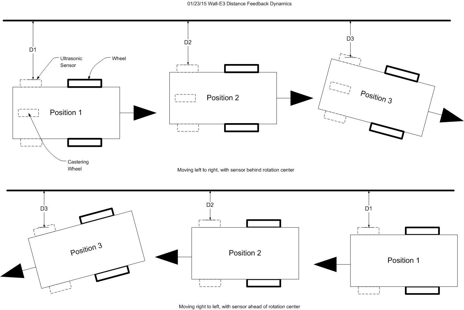
Wall-E3 Distance Feedback Dynamics
In the figure, the top half illustrates the sensor and drive wheel layout, and shows the direction of travel as initially designed and programmed. D1, D2, and D3 are successive distance measurements processed by the program. At Position 2, the robot has determined that it needs to move away from the wall, and so speeds up the left motor and slows down the right motor, leading to Position 3. However, because the sensor position is well behind the center of rotation (essentially the wheel axle line), the sensor actually gets closer to the wall instead of farther away. The robot responds to this by further increasing the left wheel speed and further decreasing the right wheel speed, which makes the problem even worse, etc. This continues until the left motor is running full speed and the right motor is stopped, causing the robot to spin in place.
The bottom half of the figure shows my rather elegant (if I do say so myself) solution to this problem – simply reverse the direction of travel, which has the effect of converting the dynamics from positive to negative feedback. Position 1 and Position 2 are the same as the top half, but in Position 3, it is clear that the distance from the wall starts increasing as soon as the robot starts rotating. The robot responds by undoing its previous adjustments to the drive wheels; if it overshoots, the sensor dynamics bring it back to the centerline.
Implementing this scheme required very little work. I had to swap the left and right distance sensor and motor control leads on the Uno (easier to do it this way than to change the code), and redefine ‘forward’ to be toward the caster wheel instead of away from it. After making the above changes, I ran the wall-following test again, and lo and behold – it worked (sort of)! The following video clip shows the new-improved Wall-E3 ‘weave’.
Now that I have the robot working to the degree that it doesn’t immediately spin out of control, I can start to look for ways to improve performance, to maybe reduce the amplitude of the ‘weave’ to something reasonable. I have already incorporated the ‘NewPing‘ library (and contributed a few buckazoids to the author for a nice, elegent class library!) into the code, so I should be able to use it to speed things up.
Stay tuned for further adventures of Wall-E, the wall-following robot!
01/24/2015 – Update to the ‘Robot Weave’ saga: I cleaned up the code a bit and hopefully sped things up a little. The following video was taken in our kitchen a few minutes ago