Posted 12/22/2015,
As I write this, I’m watching the Space-X video webcast following their historic launch and first stage recovery at Cape Canaveral. I am absolutely ecstatic that someone (in this case Elon Musk and Space-X) finally got a clue and got past the “throw everything away” mentality of previous generations. Also, as a retired civil servant, I am more than a little embarrassed that our great and mighty U.S. Government, with its immense resources couldn’t get its collective head out of it’s collective ass and instead gets its ass handed to it by Elon Musk and Space-X. I’m sure for Elon this was just another day in his special toy factory, but it was a great day for U.S. entrepreneurship and individual initiative, and just another shameful lapse for our vaunted U.S. Government space ‘program’.
OK, so much for my ranting :-). The reason for this post is to describe two major upgrades to the Wall-E2 4WD robot; a new, more powerful battery pack, and the addition of a Pololu Wixel wireless link to the robot.
New Battery Pack:
For Wall-E1 I used a pair of 2000maH Li-Po cells from Sparkfun, coupled with their basic charger modules and a relay to form a 7.4V stack. This worked fine for the 2-motor Wall-E1, but I started having problems when I used this same configuration for the 4-motor Wall-E2. Apparently, these Li-Po cells incorporate some current limiting technology that disconnects a cell when it senses an over-current situation. Although I’m not sure, I suspect they are using something like a solid-state polyfuse, which transitions from a low resistance state to a high resistance state when it gets too hot. When this happens, it can take several minutes for the polyfuse to cool back down to the point where it transitions back to the low resistance state. I discovered this when Wall-E2 started shutting down for no apparent reason, and voltage measurements showed my 2-cell stack was only producing 3.5V or so, i.e. just one cell instead of two :-(. At first I thought this was a wiring or relay (I use a relay to switch the cells from series to parallel configuration for charging) problem, but I couldn’t find anything wrong, and by the time I had everything opened up to troubleshoot, the problem would go away! After two or three iterations of this routine, I finally got a clue and was able to observe the battery voltage transition from 3.5V or so back to the normal 7.4V, all without any intervention from me. Apparently the additional current required to drive all 4 motors was occasionally exceeding the internal current trip point on at least one of the cells – oops!
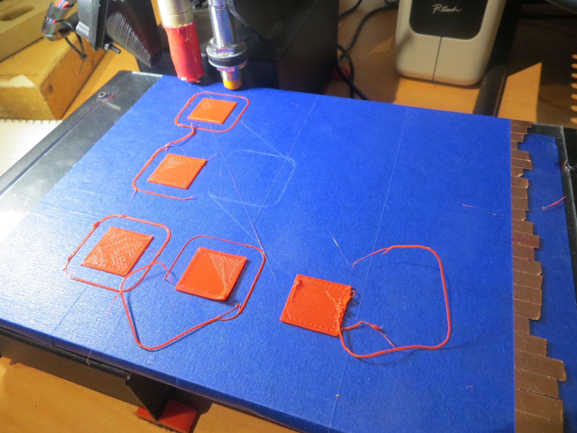
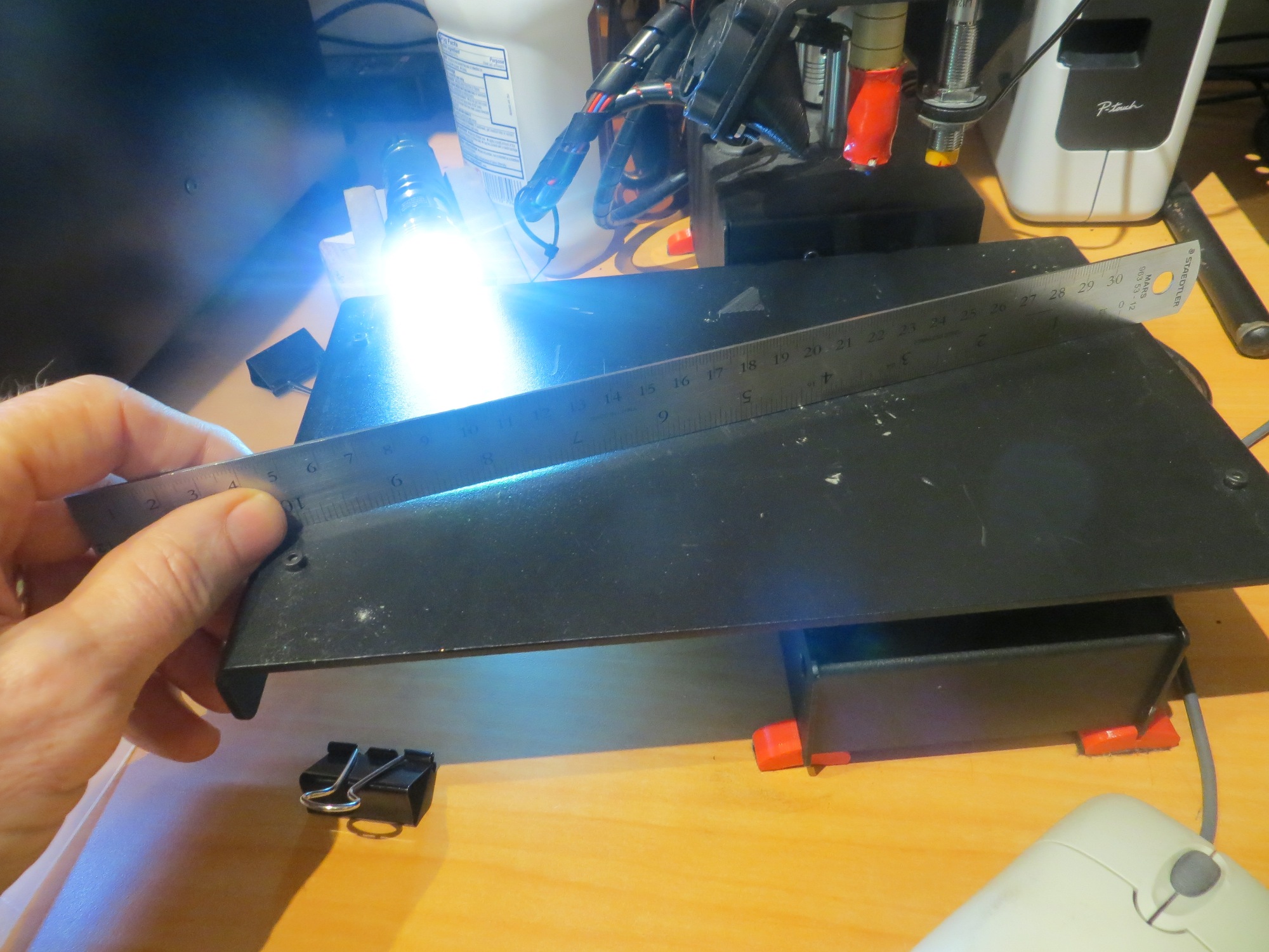
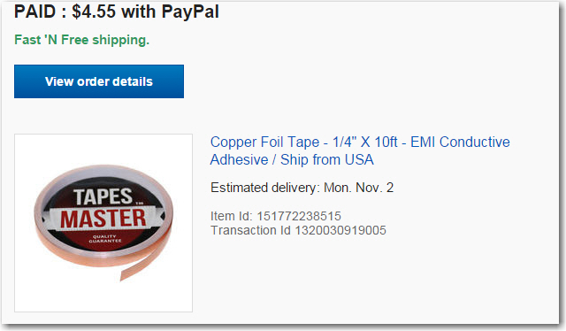
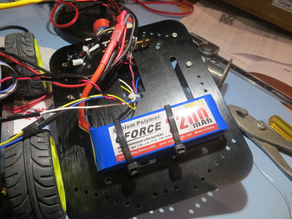
So, I started looking for a Li-Po battery pack without the too-low peak current limitation, and immediately ran into lots of information on battery packs for RC cars and aircraft. These jewels have abou the same AH rating as my current cells, but have peak current ratings in the 20-40C range – just what I was looking for. Now all I had to do was to find a pack that would fit in/on my robot, without looking like a hermit crab carrying a shell around. I eventually settled on the GForce 30C 2200mAh 2S 7.4V LiPO from Value Hobby, as shown in the following screenshot.

New battery pack for Wall-E2
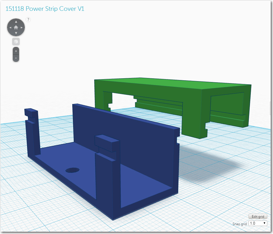
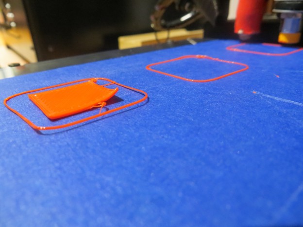
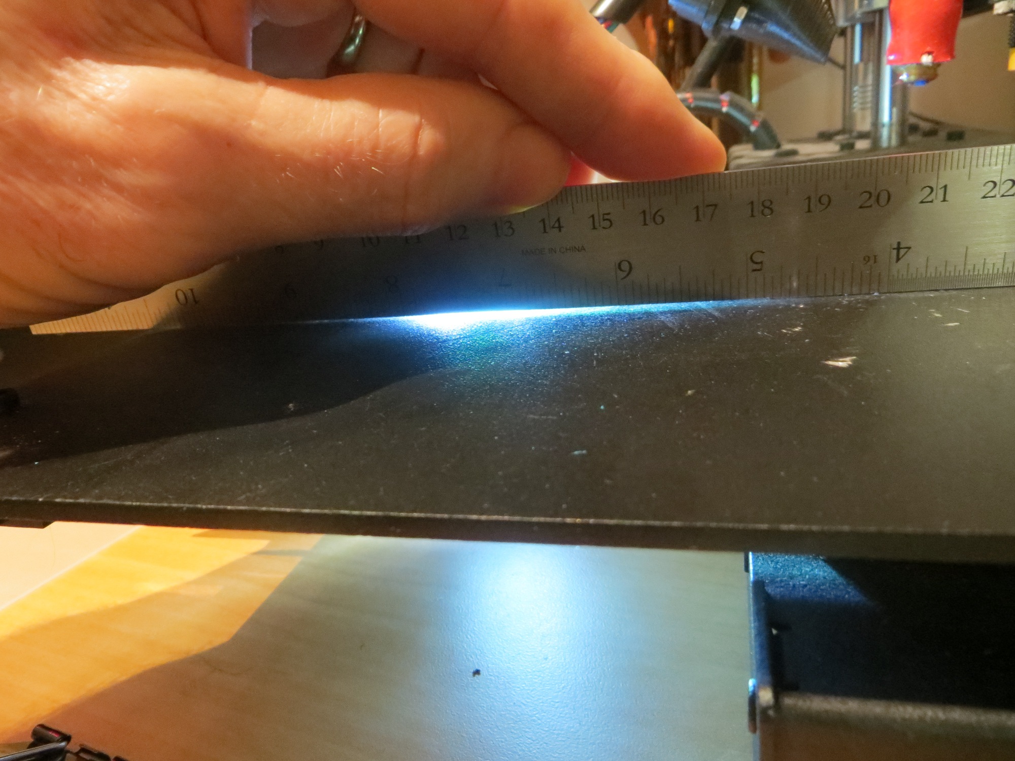
This pack is quite a bit larger (102mm X 34mm X 16mm) than the original 2000mAH cells from Sparkfun, and also requires a different (and much more expensive) charger. At first I thought I would have to mount this monster on the top of the top deck, as shown below,
Original mounting idea for the new battery
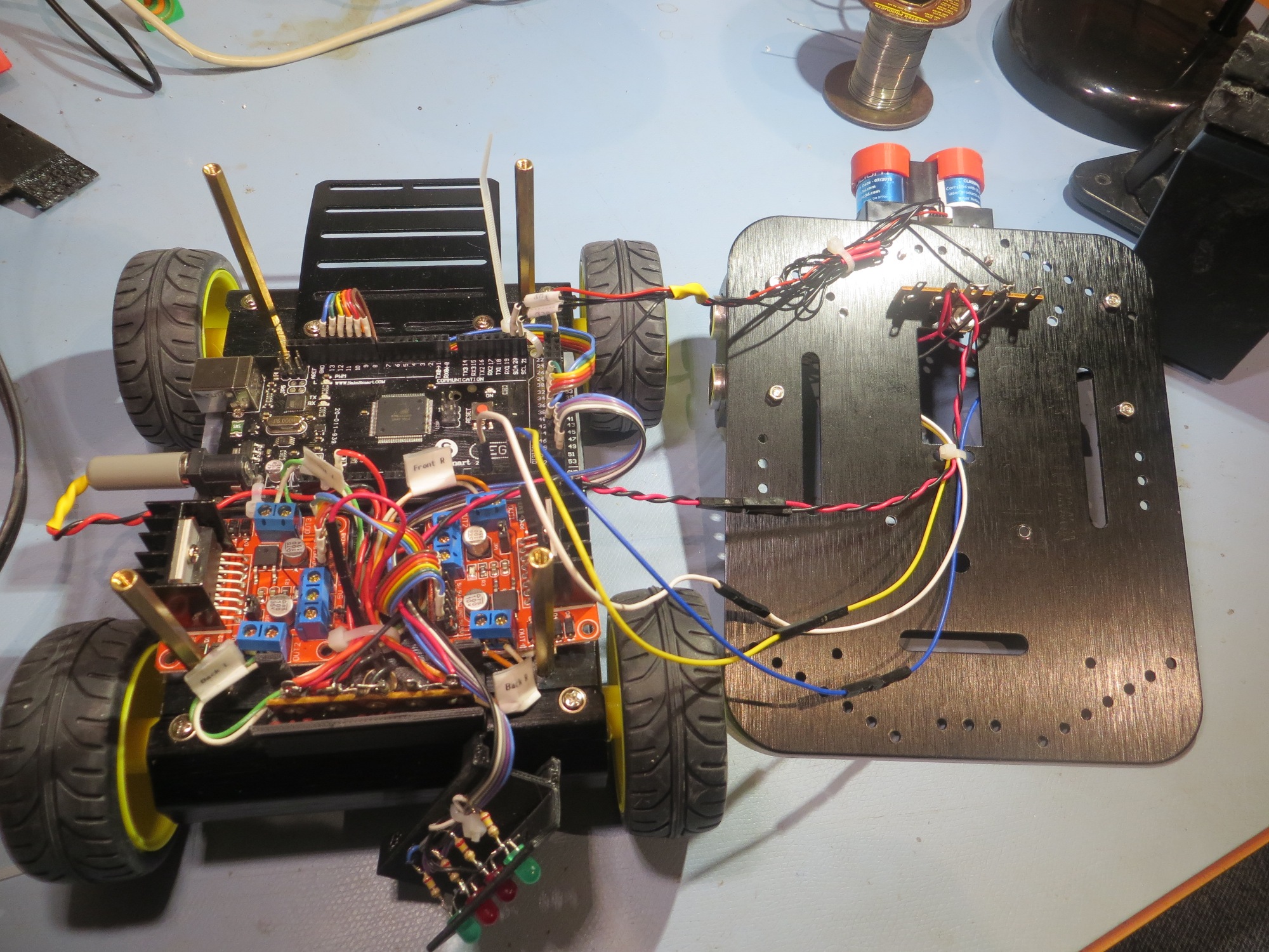
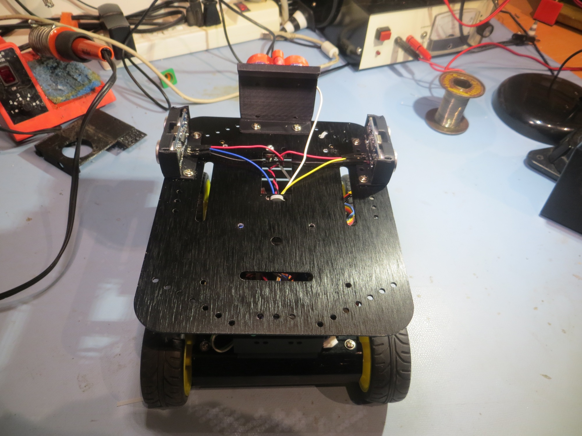
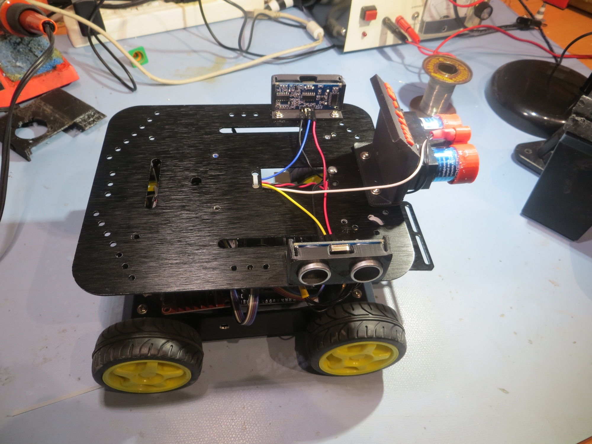
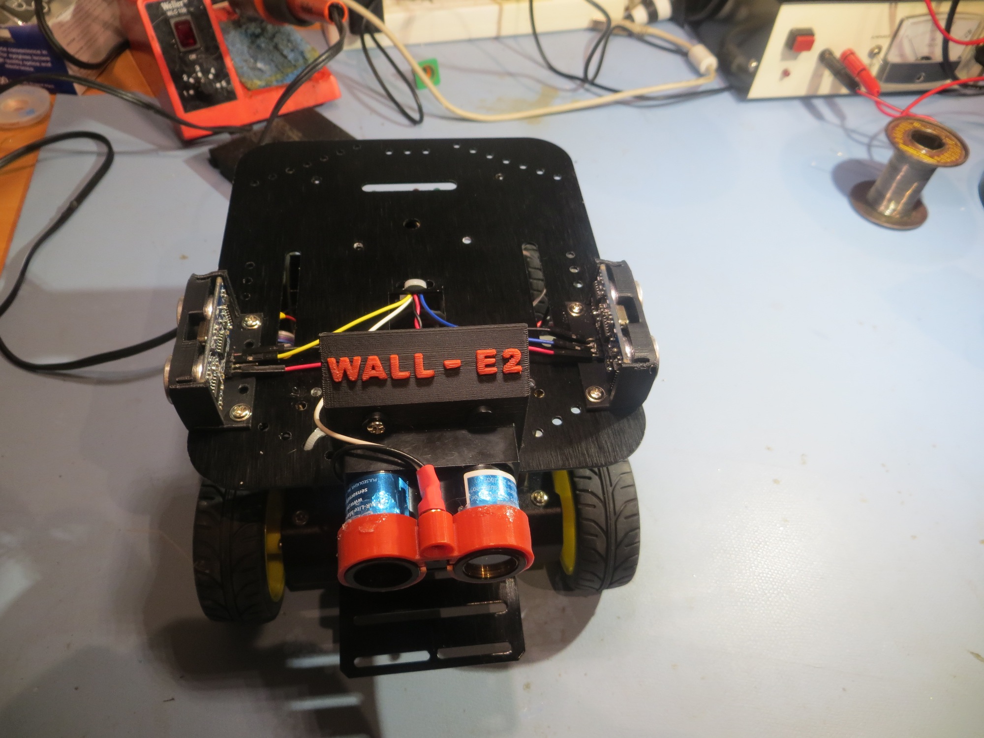
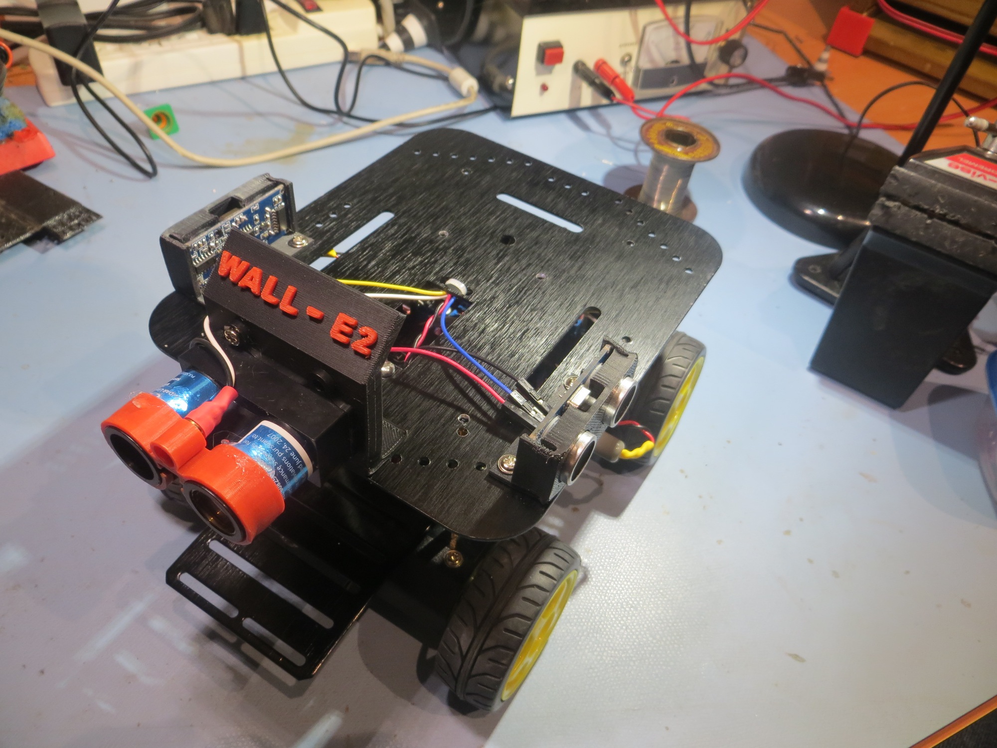
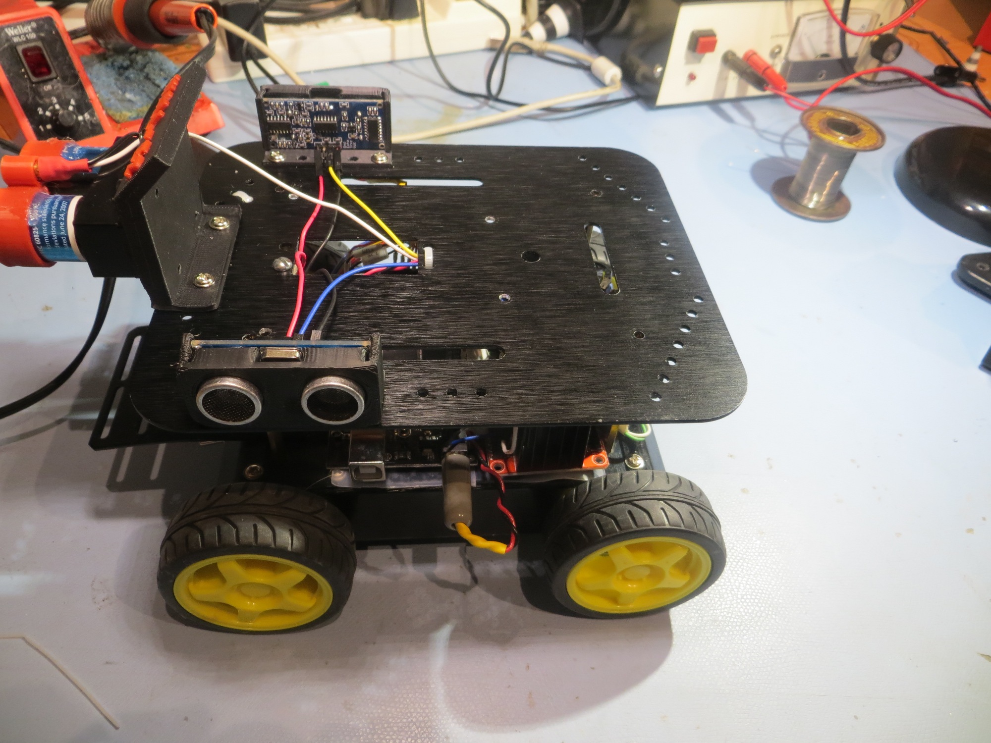
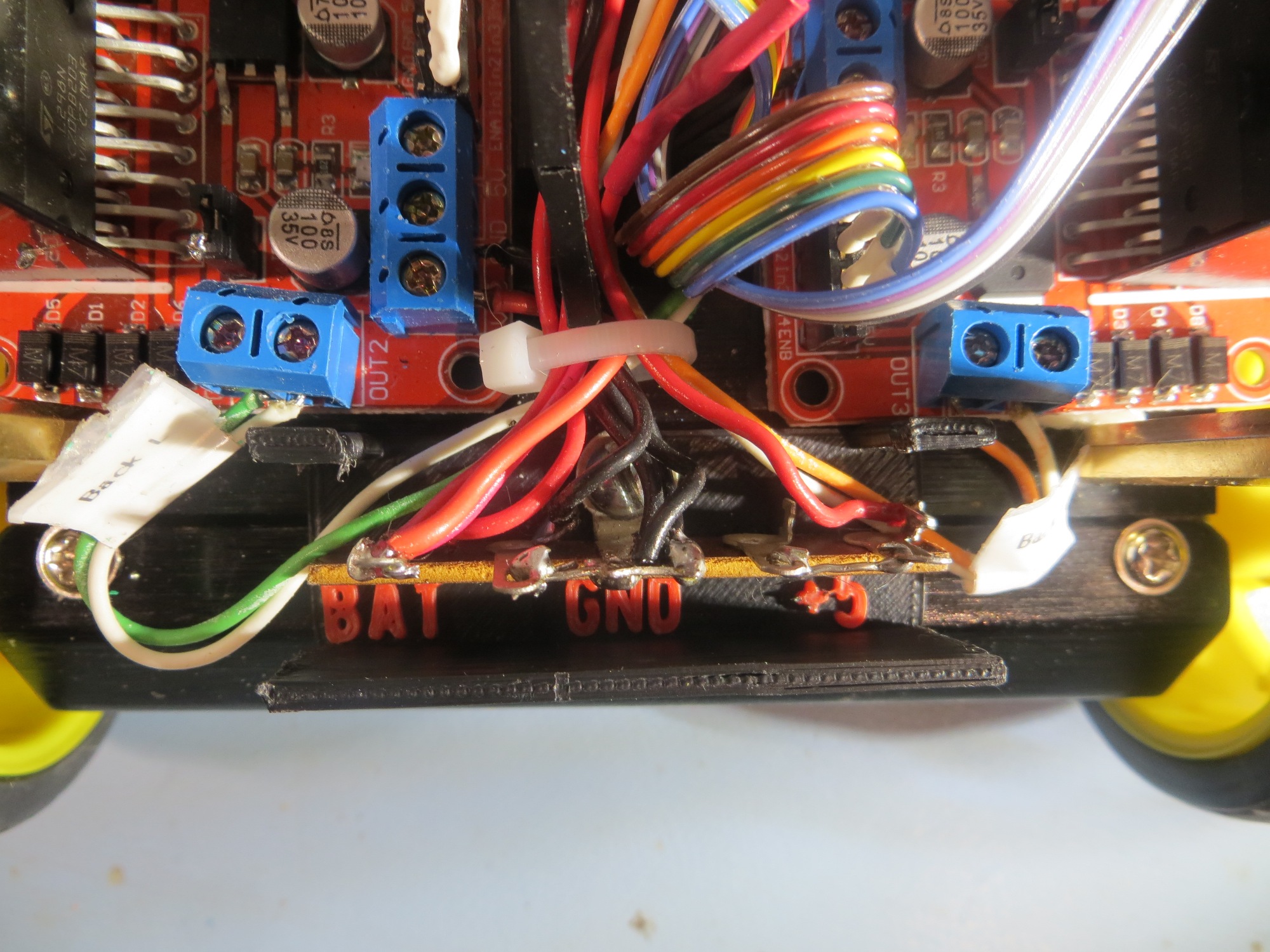
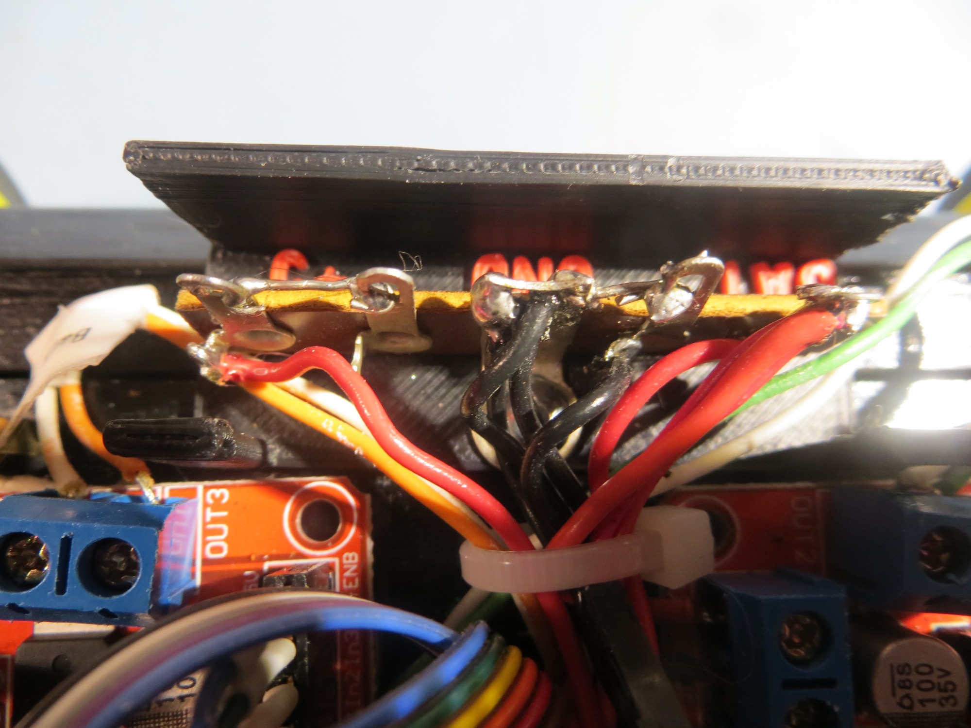
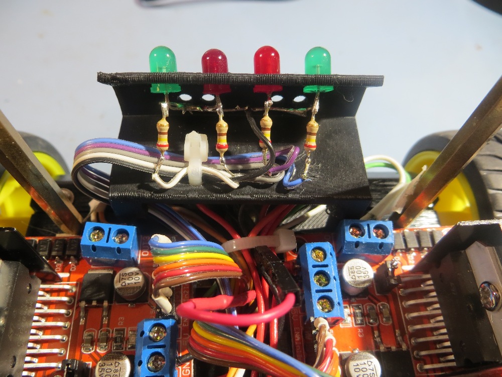
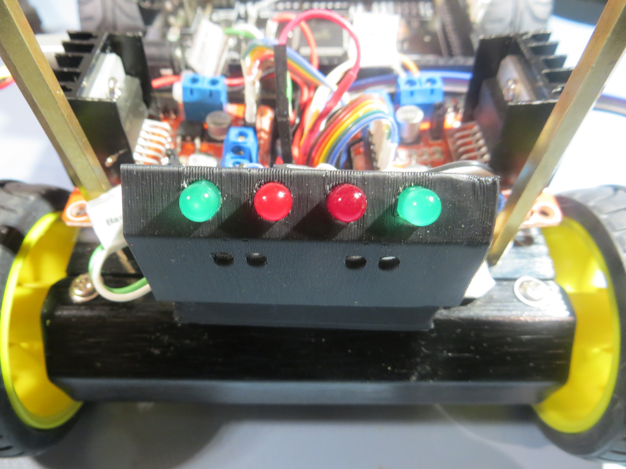
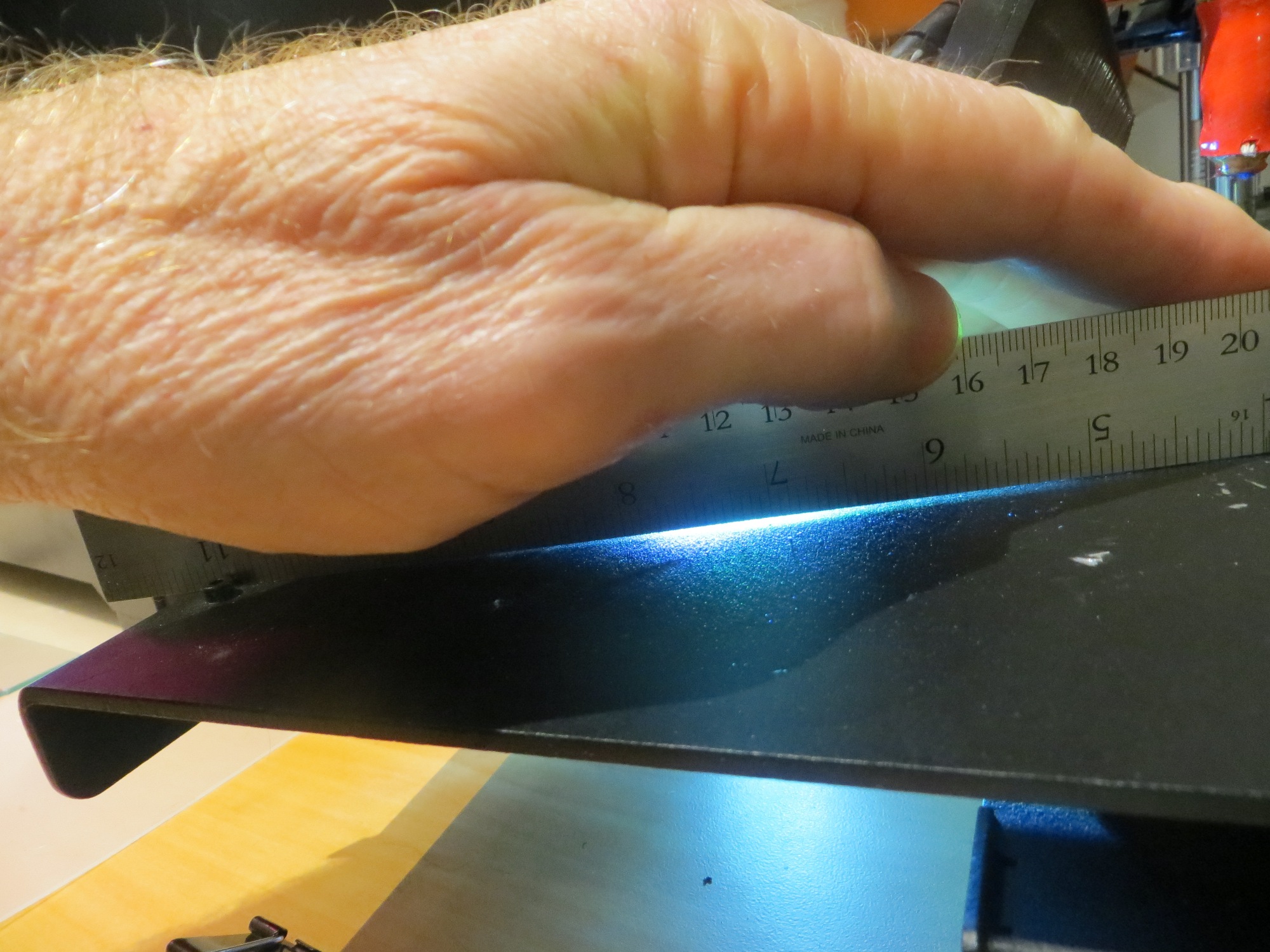
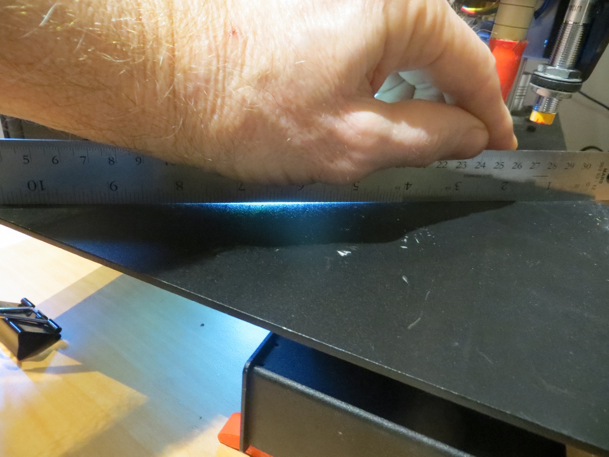
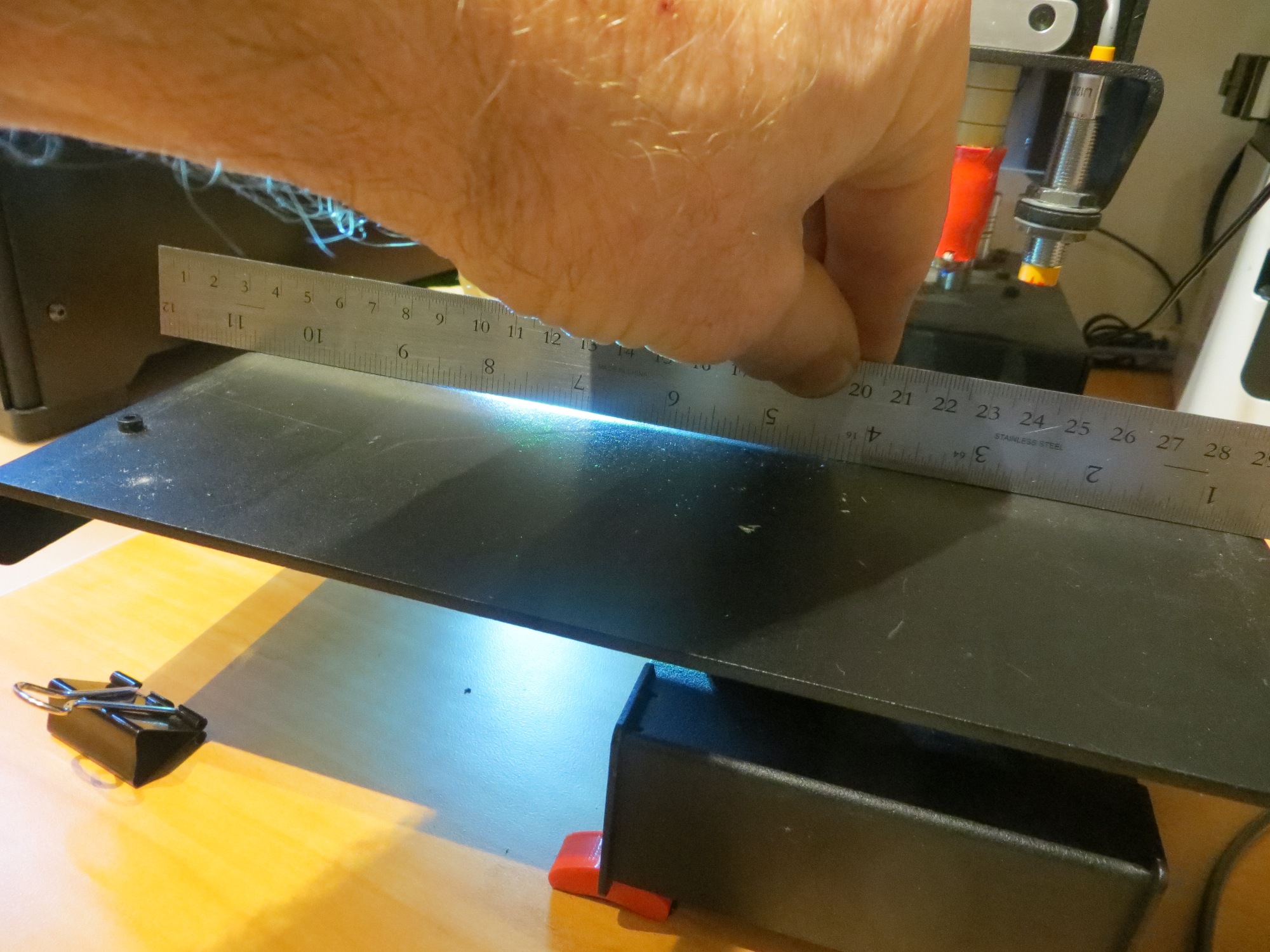
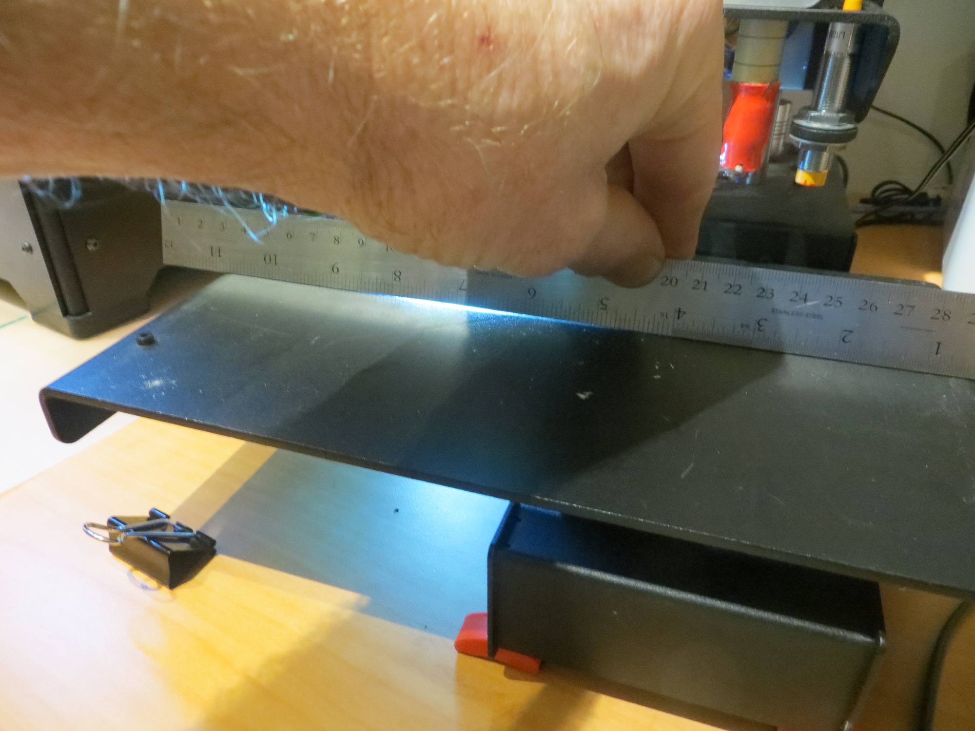
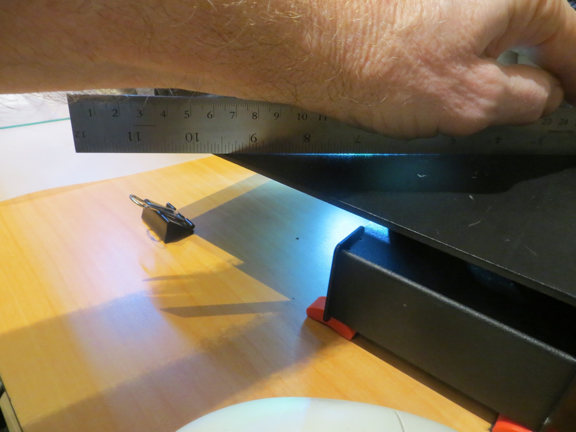
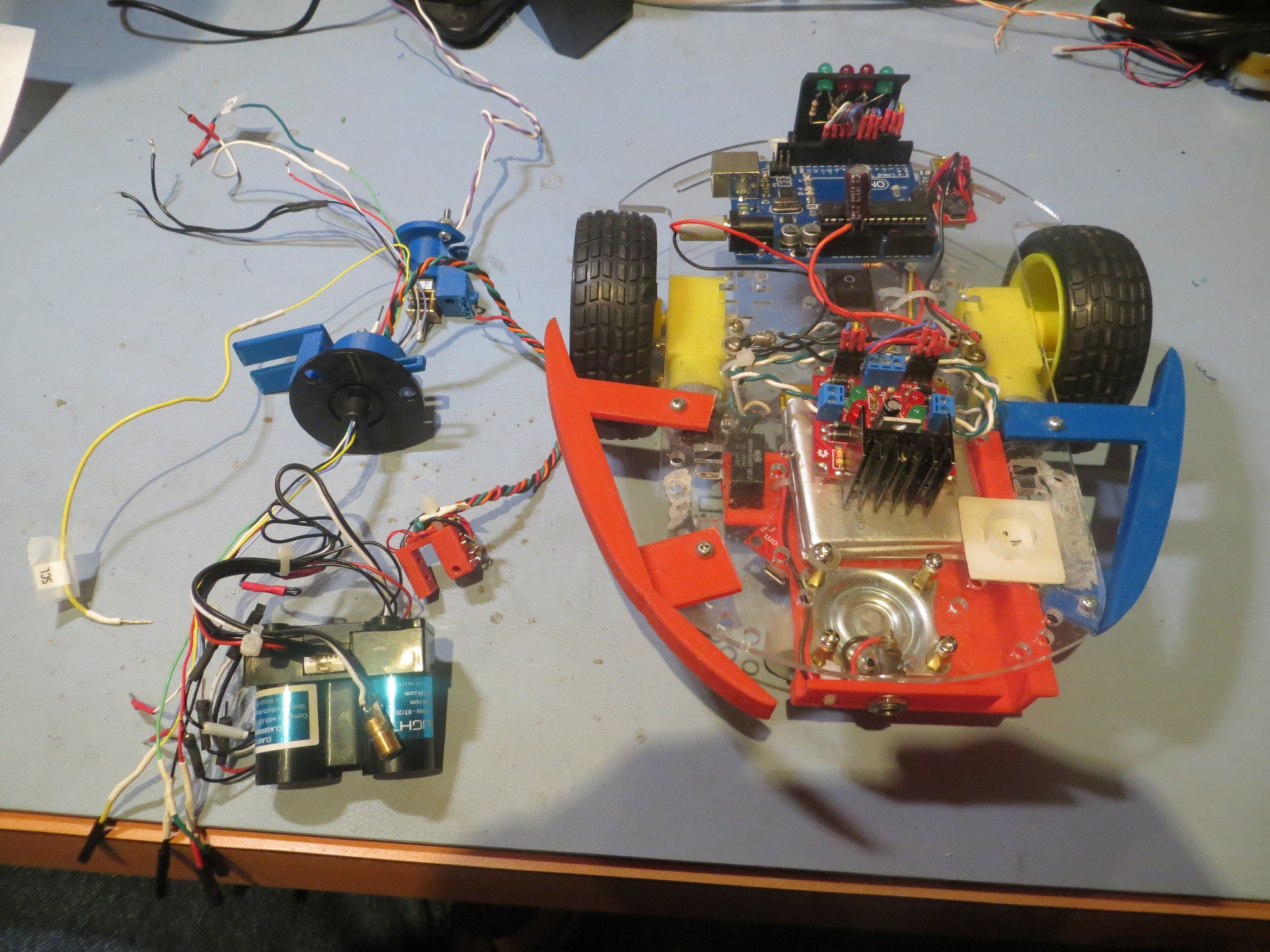
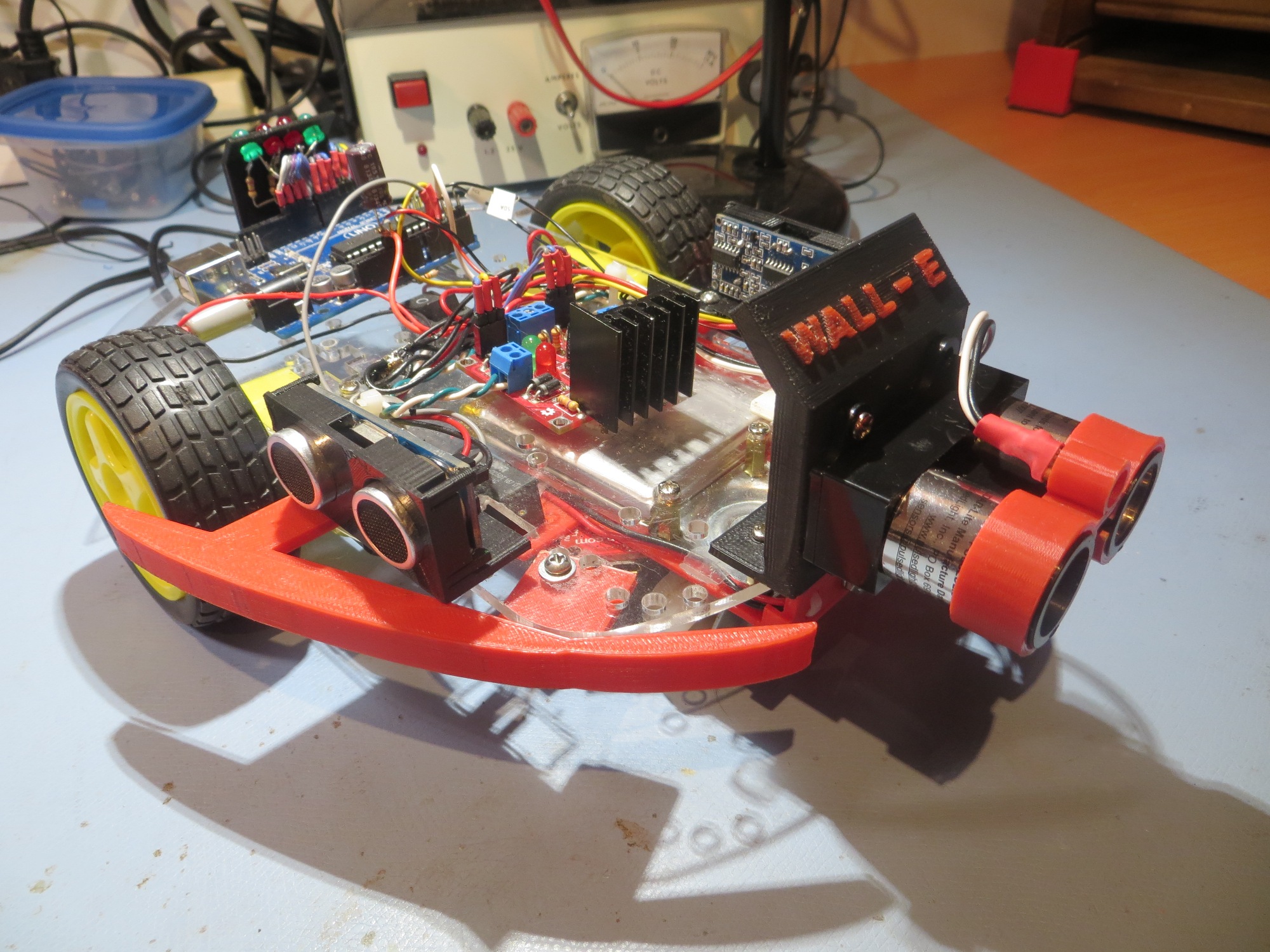
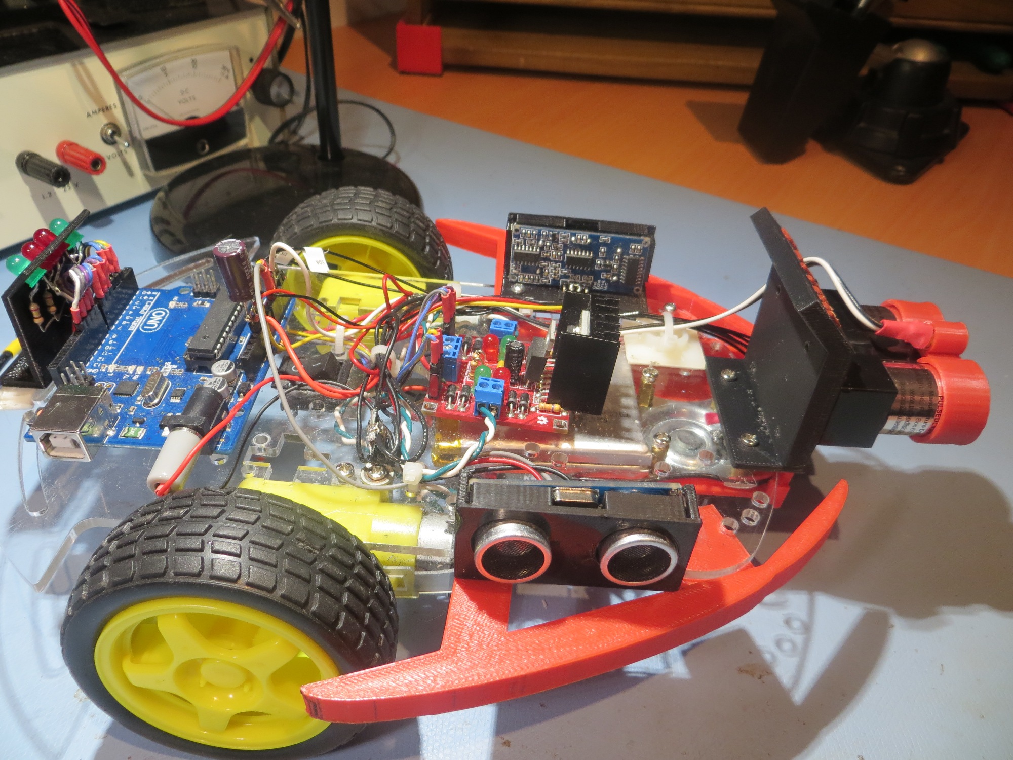
but then I figured out that I could actually mount it on the underside of the top deck, leaving the top deck area available for other stuff (in case one of the cats decides to take a ride), as shown in the next two photos.
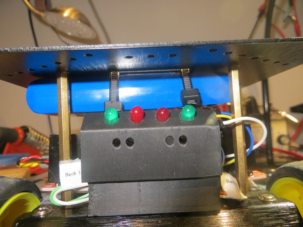
under-deck mounting, looking from rear of robot
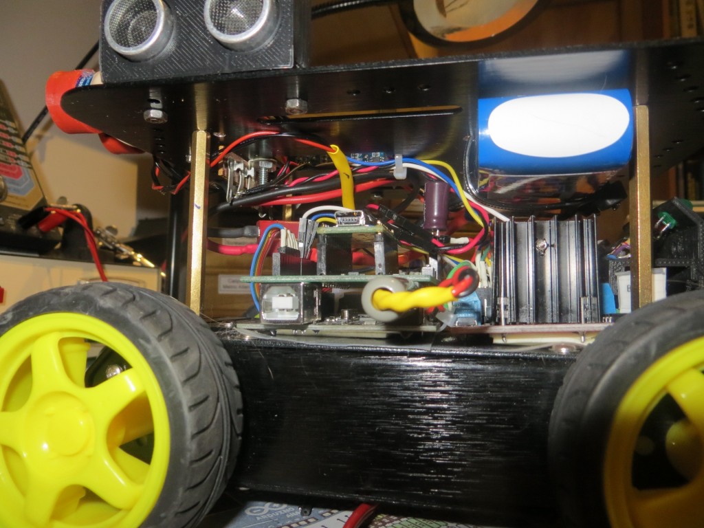
under-deck mounting, looking from side of robot
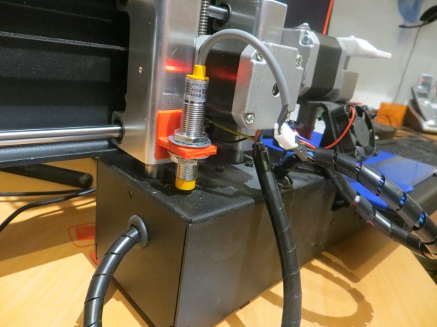
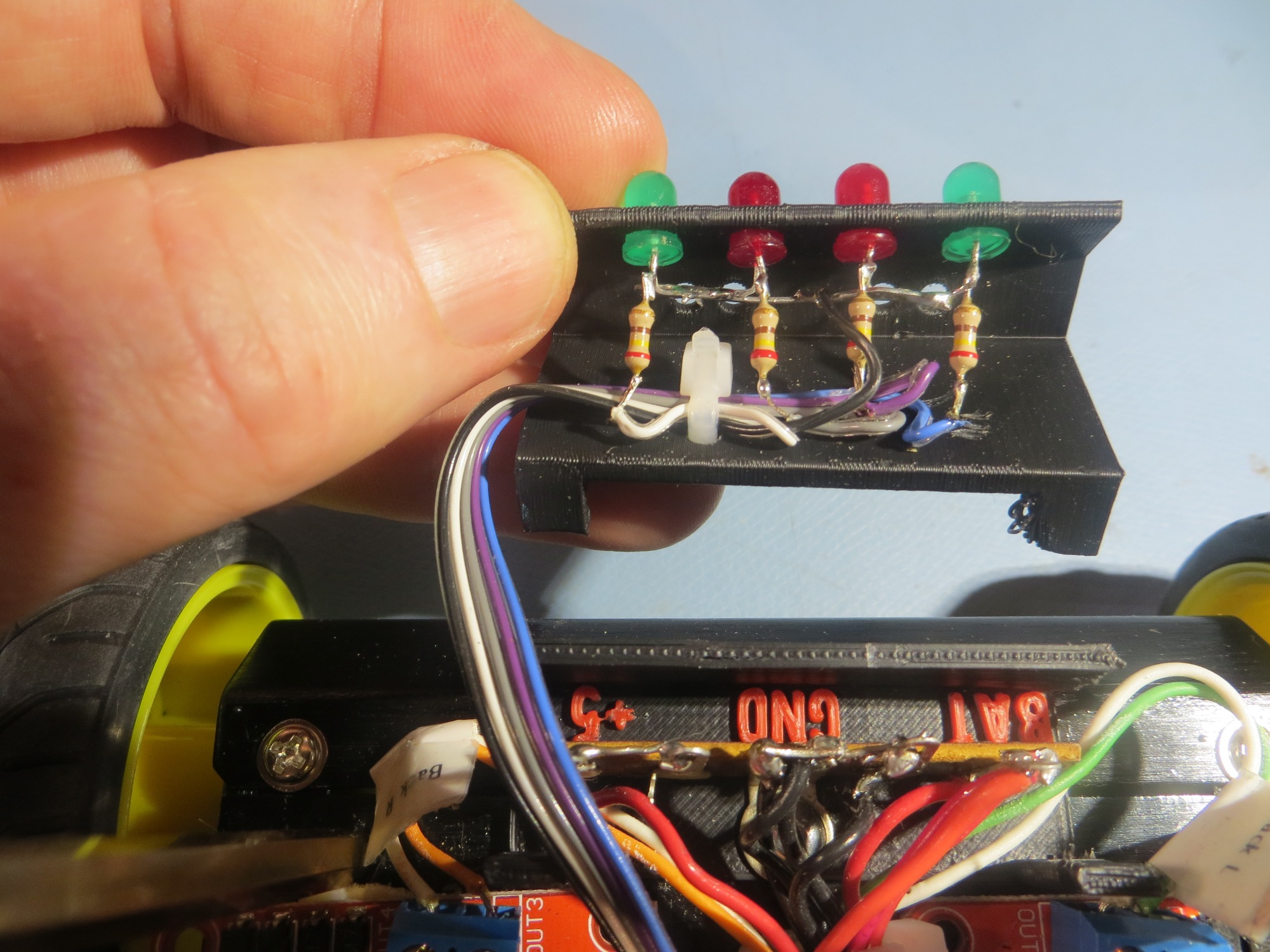
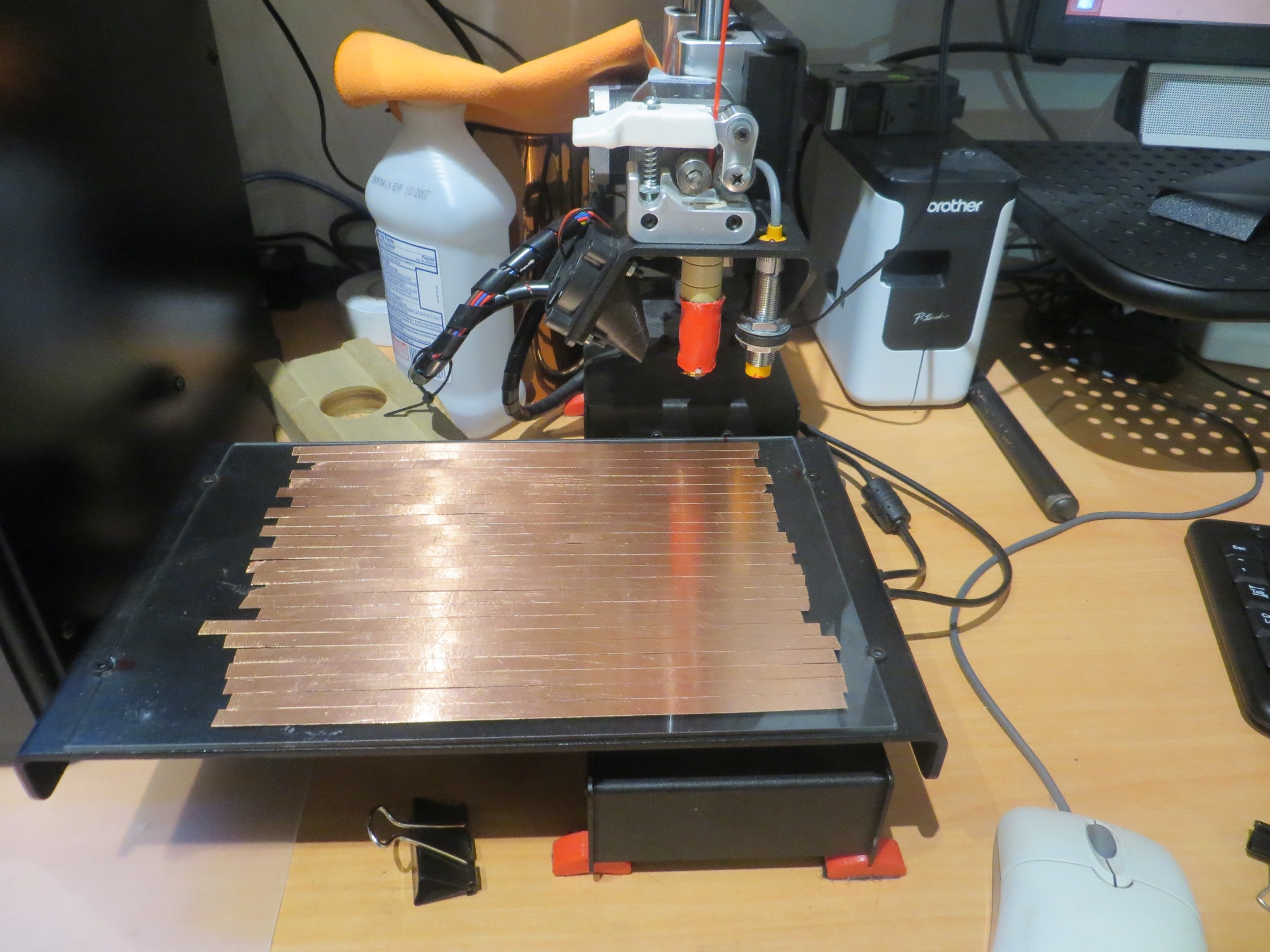
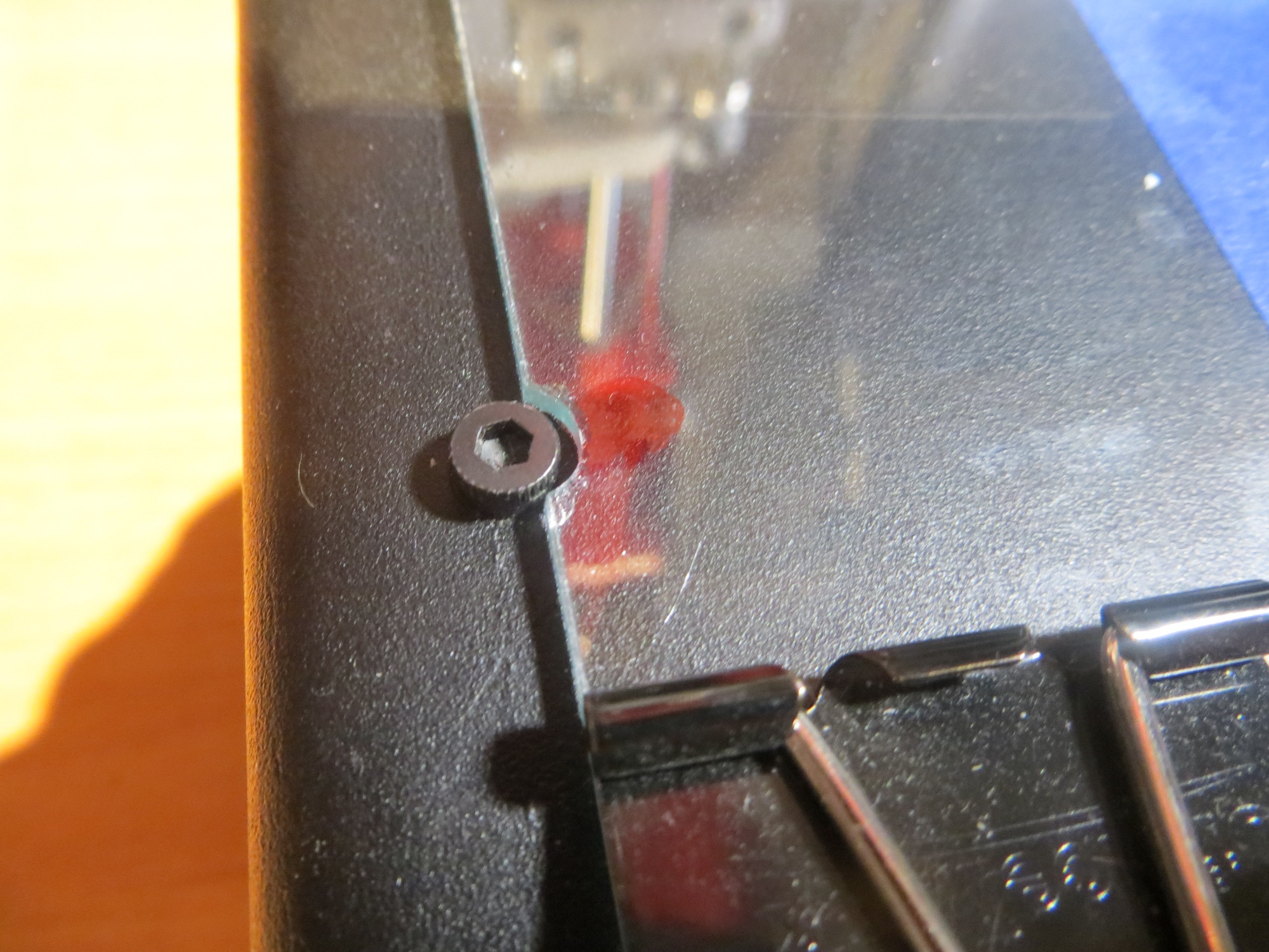
After getting the battery pack mounted, I removed the existing battery pack and associated wiring from the motor compartment, and spliced in the new battery wiring through the existing power switch, as shown below (the power switch is shown at the extreme right side of the photo. The red wire is from the battery + terminal, and the black wire from the battery was spliced into the existing ground wire.
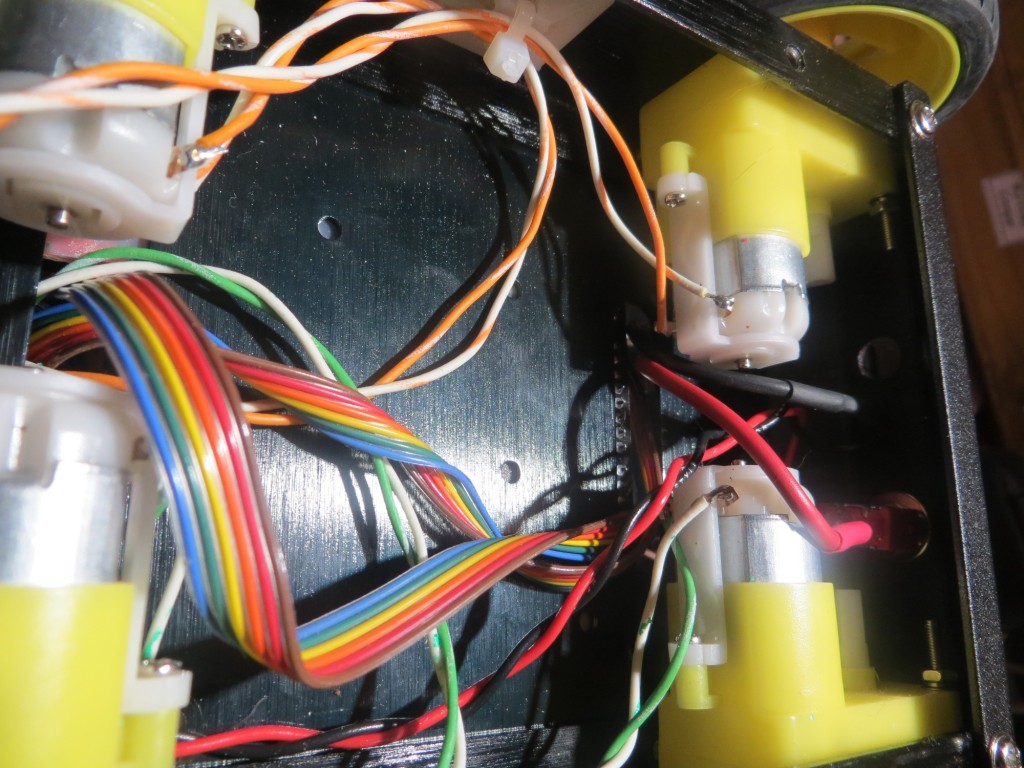
Empty battery compartment showing new battery wiring at front
Pololu Wixel Wireless Link:
As I continued to improve Wall-E2’s wall following ability, I became more and more frustrated with my limited ability to monitor what Wall-E2 was ‘seeing’ as it navigated around my house. When ‘field’ testing, I would follow it around observing it’s behavior, but then I would have to imagine how the observed behavior related to the navigation code. Alternatively, I could bench test the robot with it tethered to my PC so I could see debugging printouts, but this wasn’t at all realistic. What I really needed was a way for Wall-E2 to wirelessly report selected sensor and programming parameters during field testing. A couple of years ago I had purchased a pair of Wixels from Pololu for another project, but that project died before I got around to actually deploying them. However, I never throw anything away, so I still had them hanging around – somewhere. A search of my various parts bins yielded not only the pair of Wixels, but also a Wixel ‘shield’ kit for Arduino microcontollers – bonus points!!
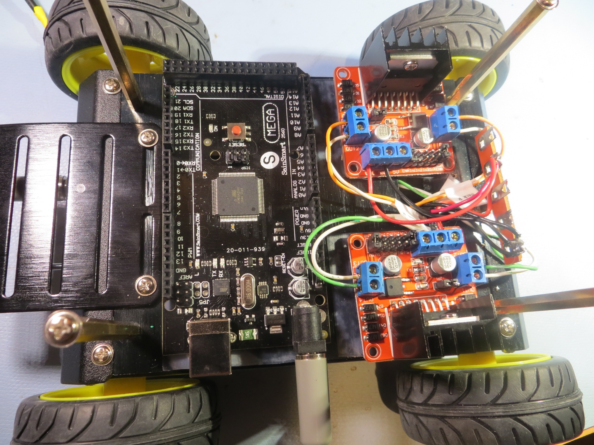
After re-educating myself on all things Wixel, and getting (with the help of the folks on the Pololu support forum) the Wixel Configuration Utility installed and running, and after assembling the Wixel shield kit, I was able to implement a wireless link from my PC to the Arduino on the robot. Pololu has a bunch of canned Wixel apps, and one of them does everything required to simulate a hard-wired USB cable connection to the robot – very nice!! And, the Wixel shield kit comes with surface-mounted resistive voltage dividers for converting the 5V Arduino Tx signals to 3.3V Wixel Rx levels, and a dual-FET non-inverting upconverter to convert 3.3V Wixel Tx signals to 5V Arduino Rx levels – double nice! Even better, the entire thing plugs into the existing Arduino header layout, for a no-brainer (meaning even I would have trouble getting it wrong) installation, as shown in the following photo.
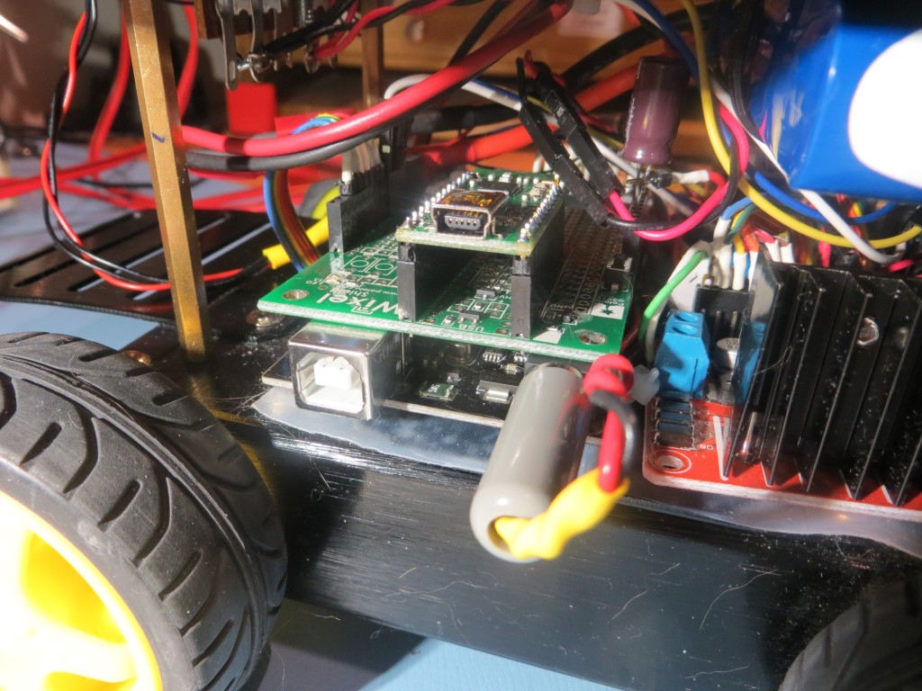
Wixel shield mounted on top of Arduino ‘Mega’ micro-controller
After getting everything installed and working, it was time to try it out. I modified Wall-E2’s code to print out a timestamp along with all the other parameters, so I could match Wall-E2’s internal parameter reporting with the timeline of the video recording of Wall-E’s behavior, and this turned out to work fantastically well. The only problem I had was the limited range provided by the Wixel pair, but I solved that by putting my laptop (with the ‘local’ Wixel attached) on my kitchen counter, approximately in the middle of my ‘field’ test range. Then I set Wall-E2 loose and videoed its behavior, and later matched the video timeline with the parameter reports from the robot. I found that the two timelines weren’t exactly synched up, but they were within a second or two – close enough so that I could easily match observed behavior changes with corresponding shifts in measured parameters. Here’s a video of a recent test, followed by selected excerpts from the parameter log.
The video starts off with a straight wall-following section, and then at about 10 seconds Wall-E2 encounters the door to the pantry, which is oriented at about 45 degrees to the direction of travel. When I looked at the telemetry from WallE2, I found the following section starting at 11.35 seconds after motor start:
Time Left Right Front Tracking Variance Left Spd RightSpd
11.46 21 200 400 Left 474 90 215
11.51 21 200 63 Left 475 90 215
11.56 21 200 400 Left 435 90 215
—- Starting Stepturn with bIsTrackingLeft = 1
11.60 21 200 56 Left 476 255 50
11.65 20 200 53 Left 525 255 50
11.71 20 200 52 Left 589 255 50
11.76 20 200 53 Left 640 255 50
11.81 20 200 52 Left 692 255 50
[deleted section]
12.31 26 200 53 Left 1107 255 50
12.35 24 200 55 Left 1136 255 50
12.40 23 200 61 Left 1155 255 50
12.46 23 200 99 Left 1151 175 130
12.51 22 200 188 Left 1320 215 90
The lines in green are ‘normal navigation lines, showing that Wall-E2 is tracking a wall to its left, about 20-21 cm away (the first value after the timestamp), and is doing a good job keeping this distance constant. It is more than 200cm away from anything on its right, and the distance to any forward obstruction is varying between 400+ (this value is truncated to 400cm) and 63 cm (this variation is due to Wall-E2’s left/right navigation behavior).
Then between 11.56 and 11.60 sec, Wall-E2 detects the conditions for a ‘step-turn’, namely a front distance measurement less than about 60 cm (note the front distance of 56 cm – third value after the timestamp). The ‘step-turn’ behavior is to apply full power to the motors on the same side as the wall being tracked, and slow the outside motors, until the front distance goes back above 60cm. The telemetry and the video shows that Wall-E2 successfully executes this maneuver for about 1 second, before the front-mounted LIDAR starts ‘seeing’ beyond the pantry door into the hallway behind, as shown by the pointing laser ‘dot’.
Similarly, at about 28 seconds on the video, Wall-E2 gets stuck on the dreaded furry slippers (the bane of Wall-E1’s existence), but gets away after a few seconds of spinning its wheels. From the telemetry shown below, it is clear that Wall-E2’s new-improved ‘stuck’ detection & recovery algorithm is doing it’s job. The ‘stuck’ detection algorithm computes a running variance of the last 50 LIDAR distance measurements. During normal operation, this value is quite high, but when Wall-E2 gets stuck, the LIDAR measurements become static, and the computed variance rapidly decreases. When the variance value falls below an adjustable threshold (currently set at 4), a ‘stuck condition’ is declared, and the robot backs up and turns away from the nearest wall. As you can see from the telemetry excerpt below, this is precisely what happens when Wall-E2 gets stuck on the ‘slippers from hell’. In the excerpt below, I have highlighted the calculated variance values.
30.96 77 26 26 Left 99 255 50
31.01 77 27 27 Left 88
31.36 77 27 26 Lef
31.51 77 28 22 Left 21 255 50
31.56 77 28 23 Left 18 255 50
31.61 77 26 25 Left 14 255 50
31.67 76 27 26
31.71 76 26 27 Left 9 255 50
31.76 76 27 25 Left 6 255 50
31.81 76 27 26 Left 5 255 50
———- Stuck Condition Detected!!———–
31.86 77 26 28 Left 4 127 127
34.13 61 200 117 Left 167 255 50
34.18 62 200 118 Left 325 215 90
This ‘field’ trial lasted less than two minutes, but the combination of the timestamped video and the timestamped telemetry log allowed me a much better understanding of how well (or poorly) Wall-E’s navigation and obstacle-avoidance algorithms were functioning. Moreover, now that I can record and save video/telemetry pairs, I can more precisely assess the effects of future algorithm developments (like maybe the addition of PID-based wall following).
So, the combination of the new battery pack and the Wixel wireless link has given Wall-E2 some new super-powers. It can now drive around with much greater energy, and it can now tell its human masters what it is thinking while it goes about its work – doesn’t get much better than that!
Stay tuned!
Frank