In our last episode of the Flap Handle Follies, I was sure I had all the bases covered.
- Larger set-screws in grip – check!
- 1/4 turn locking latch connecting flap grip to remote caddy assembly – check!
- Rotatable remote caddy with spring-plunger detent every 10 degrees – check!
Unfortunately, one essential item for success with this version was missing from my checklist, and its absence spelled doom:
- Non-gorilla pilot – check!
A few days after sending the latest version to John, I got an email with some photos and suggestions, and a few days after that I got my folded/stapled/mutilated flap handle assembly back – boy was I embarrassed! What I had thought was a *brilliant* solution to a problem turned out to be not-so-brilliant when exposed to a pilot who expected things to go together in a particular way. I had designed the 1/4 turn locking mechanism so the locking direction was opposite the normal “righty-tighty” direction because by doing so, the pilot’s normal thumb position on the remote caddy tended to hold the caddy locked onto the flap grip, as opposed to tending to unlock it. Unfortunately, I had forgotten to mention this feat of brilliance to my friend, who expected everything to conform to normal lock/unlock conventions – oops!
Ah, well – it wasn’t a total failure, because we learned some things in the process:
- The 3-piece assembly (flap grip, grip-to-caddy converter, caddy) was too long; John couldn’t reach the CN remote’s buttons with his thumb while his hand was comfortably placed on the flap grip.
- The 1/4-turn locking mechanism was way too fragile (jokes about gorilla pilots notwithstanding)
- The dimensions of the rectangular slot in the grip piece seemed to be just about right.
So, back to the drawing board yet again. hunting through the forest of design possibilities for just the right combination.
- Minimize or eliminate the grip-to-caddy converter to reduce overall length
- Enlarge/strengthen the 1/4-turn locking mechanism (but keep the opposite direction actuation)
Minimizing or eliminating the converter piece required that I drop the caddy rotation feature. This was kind of overkill anyway, as John had marked the correct (for him) rotation much earlier in the game; I was trying to generalize his preference into something other pilots could use as well. I just needed to think about the rotation feature as something ‘baked in’ to the design, rather than something pilot-adjustable.
Enlarging/Strengthening the 1/4-turn locking mechanism shouldn’t be too much trouble, as the latch parts were available in their own separate design files, so a simple scaling operation should do the trick there. The only limitation on size being that the latching mechanism has to fit into the top of the flap grip and the bottom of the converter piece.
Based on my now extensive experience with printing parts on my PrintrBot, I also added the requirement that each part be printable in a way that preserves the quality of the mating surfaces. I have come to understand that there is a right way and a wrong way to print parts; the right way result in very clean and smooth mating surfaces, while the wrong way results in ugly, bumpy surfaces that no amount of sanding can make right. Fortunately, the combination of careful design and clever positioning of the part on the print plate seems (so far) to be effective. The trick here is to make sure that parts are positioned so the mating surfaces are either perfectly parallel or perfectly perpendicular to the print plate; in either orientation the result is nice, clean surfaces. In the case of the converter part, the mating surfaces aren’t parallel to each other, so it was placed vertically on the print plate so the larger mating surface (remote caddy interface) was perpendicular to the print plate, and the smaller (flap grip) surface was tilted 20 degrees from the vertical. Near-vertical surfaces also print very well, so this resulted in both mating surfaces printing nicely, but the cost was a much longer printing time (2 -3 hours vs about 15 minutes!).
In the previous version, the thickness of the grip-to-caddy converter part was driven by the need for the caddy to rotate on the converter-to-caddy mating surface, which required that the converter have a hole deep enough to accommodate a reasonably sized axle post on the caddy part. Eliminating the rotation feature allowed me to eliminate much of this thickness. I still had the following requirements:
- The caddy has to be rotated about 25 degrees CCW with respect to the fore-and-aft centerline of the flap grip, when looking at the top of the caddy. This value was measured from John’s marks on an earlier version.
- The caddy has to be tilted vertically about 20 degrees with respect to the flap grip mating surface (again taken from John’s feedback).
To implement the ‘minimized’ grip-to-caddy converter piece, I went back to Autodesk 123d Design’s ‘sketch loft’ feature. This is a very cool capability, and makes it (just) worthwhile to deal with 123d Designs many other ‘non-linear frustrations’ (see 2014/10/tinkercad-vs-123d-design-vs-meshmixer-pick-poison/). I started with a 2D ellipse that matches the flap grip cross-section, and then added a 2D sketch of the caddy. Then I tilted and rotated the caddy sketch as defined above, and then ‘lofted’ the ellipse sketch into the caddy sketch – voila!
-
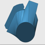
- Grip-to-Caddy bottom view showing twist
-
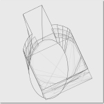
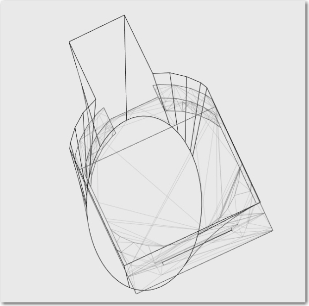
- Grip-to-Caddy wireframe view showing 25 degree CCW twist
-
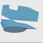
- Ellipse-to-Caddy exploded view
-
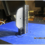
- Grip-to-Caddy converter print. Note vertical placement required to achieve smooth mating surfaces.
Now that I had the grip-to-caddy converter design worked out, all I had to do was to insert the scaled up 1/4-turn latching mechanism into the top of the grip and the bottom of the converter, and print all the parts. Scaling and inserting the latch parts turned out to be pretty easy, as I already had all the latch geometry issues worked out from the time before, and all I had to do was use Tinkercad’s uniform scaling feature to ‘grow’ the latch about 150% or so. After scaling the parts, I latched and unlatched them in Tinkercad a couple of times to make sure that Part A did indeed fit into Part B, and then simply copy/pasted them into the grip and converter designs.
There was one complicating factor; due to printing concerns, I decided to print the converter and caddy parts separately, and then screw them together using 2ea 4-40 screws. I designed matching 2mm pilot holes in both the caddy and converter mating surfaces, and I added thickness to the bottom of the caddy so I could countersink sufficiently (about 3mm) to hide the screw heads below the bottom surface of the caddy. However, when I got everything done, I wound up just gluing the parts together with gap-filling superglue from my local hobby shop, and this seemed to do much better than screws.
In summary, I was able to quickly design and implement a new flap-grip version with ‘baked-in’ caddy twist and tilt, and was able to get the caddy about 12mm (about 1/2 inch) closer to the flap grip than in the old design.
-
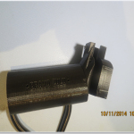
- Note the built-in strain relief loop
-
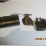
- Side exploded view
-
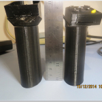
- Side by side comparison of the old and new versions. Note the newer one (on the right) is considerably shorter
As an added amenity for the pilot, I decided to design and implement a ‘caddy garage’ so John would have a place to store the caddy when it wasn’t in use. As part of the original testing program for the 1/4-turn latch, I had built some thin test pieces with the same cross-section as the flap grip – one with a plug, and one with a socket. I did the same thing for the larger latching mechanism, so all I had to do was to put some mounting holes in the socket test piece and throw it in the box with the completed flap grip/caddy assembly. John can mount the ‘garage’ in some convenient location in his cockpit, and simply latch the caddy assembly to the ‘garage’ after unlatching it from the flap grip.
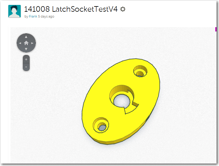
Caddy Garage. Note mounting holes for convenience
OK, off to the Post Office tomorrow to mail the new stuff to John. I hope this new version will survive the ‘Gorilla Pilot’ test in better order than the last one did! 😉
Frank
LatchLocketTest4
Mini141008
http://gfpbridge.com/2014/10/need-better-class-pilot/141008-mincvtr1/
in files I can use for Autodesk 123D? I’m just learning how to use CAD and I have a personal project underway. I’m trying to make a column taper like you have… an oval tapering spanning. Do you have a file I might have ? THANKS!!