In Part 5 of this journey, I described our paradigm shift from a joystick mounted ClearNav remote caddy to a flap grip mounted version. When John received and tested the first try at this approach, he agreed we were on the right track, but there were some ‘issues’ (there are *always* issues!).
- The cable channel in the flap grip piece is unusable, as routing the cable this way interferes with opening the canopy. Instead, John just used the single tie point on the caddy piece, and simply detached that piece when entering/exiting the glider
- The rectangular slot in the flap grip piece was a bit too roomy in the forward/aft direction.
- The finger scallops on the front of the grip didn’t really fit John’s fingers – oops!
- The caddy piece would work better if it was offset slightly forward of the flap handle centerline, and rotated about 20 degrees ‘up’ relative to the top surface of the flap grip (i.e. toward the glider centerline)
- The way that the caddy piece was attached to the flap grip prevented it from being rotated slightly to accommodate John’s actual thumb position; he suggested a round stud rather than a rectangular one.
- The remote connector (a RJ-11 phone-style connector) sticks out the front of the caddy and is vulnerable to damage; John suggested I design in some protective walls for this.
Incorporating all the above elements into a new design involved some head-scratching, and quite a few 4-letter words, as I found that none of the 3D design tools I have so far employed (TinkerCad, 123D Design, and MeshMixer) would do the whole job. I wound up working with all of them at one point or another in order to get what I wanted. In addition, I was in the process of upgrading my PrintrBot 3D printer with a heated bed to accommodate future plans to print with ABS plastic in addition to PLA, and this turned out to be a lot more complicated than I had envisaged (I eventually reverted to my original hardware configuration, as I could not get consistent prints with the heated bed).
The first three items above were trivial to solve – just deleting the relevant ‘hole’ structures from the design, and modifying the rectangular slot dimension slightly.
The last three, however, required a complete re-thinking of the way the caddy piece coupled to the top of the flap grip piece. The flap grip has an elliptical cross-section, with a top surface that is parallel to the glider centerline, while the caddy piece has a rectangular cross-section that needed to be tilted up 20 degrees to the flap grip piece. In addition, the front portion of the caddy piece needed to have significant material added to support a side wall protection structure for the RJ-11 connector. I ran through several TinkerCad versions but ultimately realized that TinkerCad just kind ran out of horsepower to handle the complex surface morphing I was looking for. I just couldn’t get any kind of a smooth transition from the elliptical flap grip shape to the essentially rectangular caddy shape *and* provide for connector walls.
An early concept for the ‘new improved’ flap grip model
An early concept for the ‘new improved’ flap grip model
However, I had been playing with 123D Design as a possible alternative to TinkerCad, and realized that it’s ‘sketch lofting’ feature might be just what I needed (assuming I could get past all the 123D Design frustrations and actually make the *%$@!#%$#* thing work! The way the ‘lofting’ feature works is to take a ‘base’ 2D sketch in an X-Y plane (in my case, an ellipse representing the top of the flap grip), and morph it into a ‘top’ 2D sketch (an outline representing the bottom of the caddy section) over the Z-axis distance between the two sketches. By doing this I hoped to get a much smoother transition from one surface to the other. After playing around with this in 123D design for a while, I actually got this feature to work (an unusual occurrence with this program!). The following two images show the basics of the feature – here I have ‘lofted’ an ellipse in the Z=0 plane to a rectangle in the Z=50 plane, rotated about the Y-axis by 20 degrees.
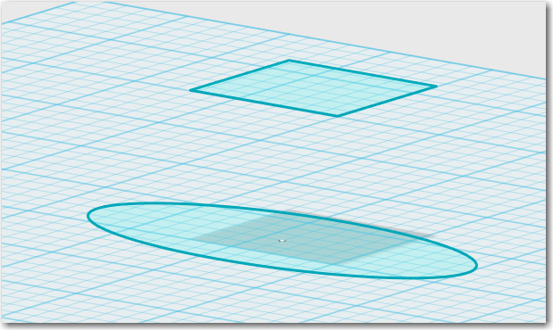
2 different 2D surfaces
An ellipse ‘lofted’ into a tilted rectangle
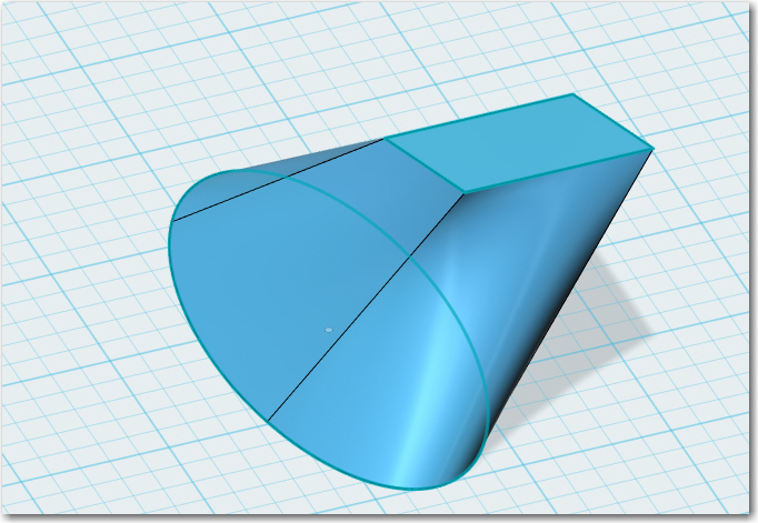
For my purposes, I imported the flap grip and caddy pieces into 123D Design, and used them as patterns for the required 2D sketches. I still needed to add the connector-guard section onto the front of the caddy section sketch, but this was fairly straightforward using the 123D Design ‘2D polyline’ feature. Once I had the two surfaces mapped out and placed at the desired heights/angles, I could use the ‘loft’ feature to create a transitional 3D structure. The first run at this is shown in the following screenshot.
First try at blending the flap grip surface to the caddy surface.
This actually worked pretty well, but I realized that the connector-guard portion of the transition structure wasn’t going to be nearly deep enough (in the Z-axis direction) to actually do any connector guarding – bummer! So I tried again using a 3-surface model, with a middle surface using the non-rotated caddy outline plus the outline of the connector guard. With this setup, I got a much more radical initial transformation from the ellipse to the caddy outline (not so good), but much more available bulk in the Z-axis direction for the connector guard (very good). On balance, the need for the additional connector guard material outweighed the aesthetics of the smoother transition, so I wound up with a transition section that looked a bit like some prehistoric alligator (minus the legs) but…
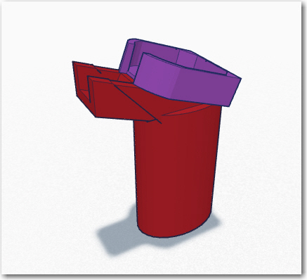
More or less final transition section from the flap grip ellipse to the caddy
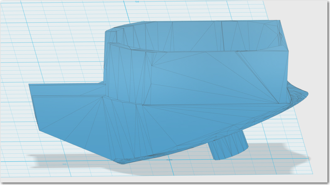
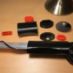
Caddy, transition section, and cylindrical mating stud
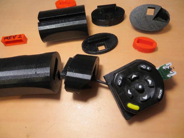
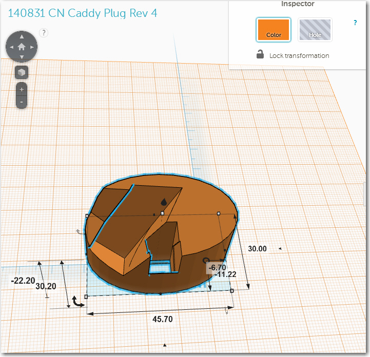
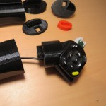
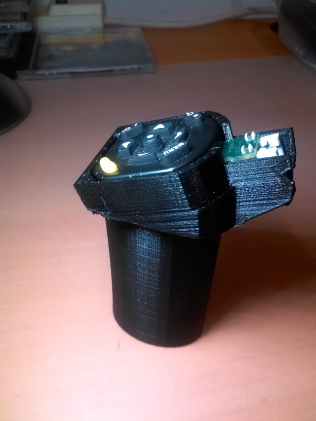
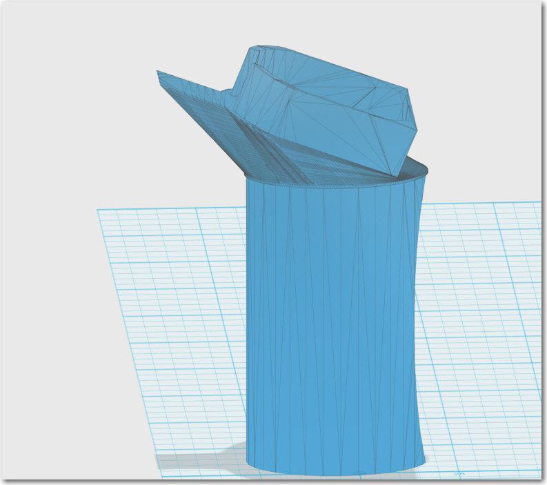
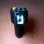
The next step was to import the transition section created in 123D Design back into TinkerCad for additional work and tuneup prior to 3D printing. It was right in here somewhere that TinkerCad (a ‘cloud-based’ application) mysteriously went away for about 24 hours, causing a major hiccup in my project and correspondingly major damage to my Wa (I had upwards of 80 design revisions in the TinkerCad cloud, and if they all went away…). Fortunately for me and my Wa, TinkerCad came back several hours later, and I was back in business. The following screenshots show the ‘final’ (as if this project will ever end!) version of the remote caddy section. The holes in the remote caddy bed were intended to accommodate the remote’s mounting screws (so they could be retained in the remote and not lost), but unfortunately the measurements were a bit off :-(. The side view shows the tie-wrap attachment ring on the front undersurface, and the mounting plug on the bottom. Both the mounting plug and the front portion of the caddy underside were shaved off a bit to create a larger attachment area for 3D printing
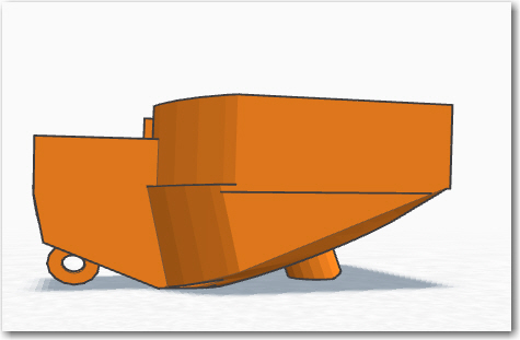
Final caddy version side view. Mating plug and front bottom portion shaved off for better 3D printing
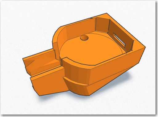
Final remote caddy version. Note holes for remote mounting screws (didn’t work)
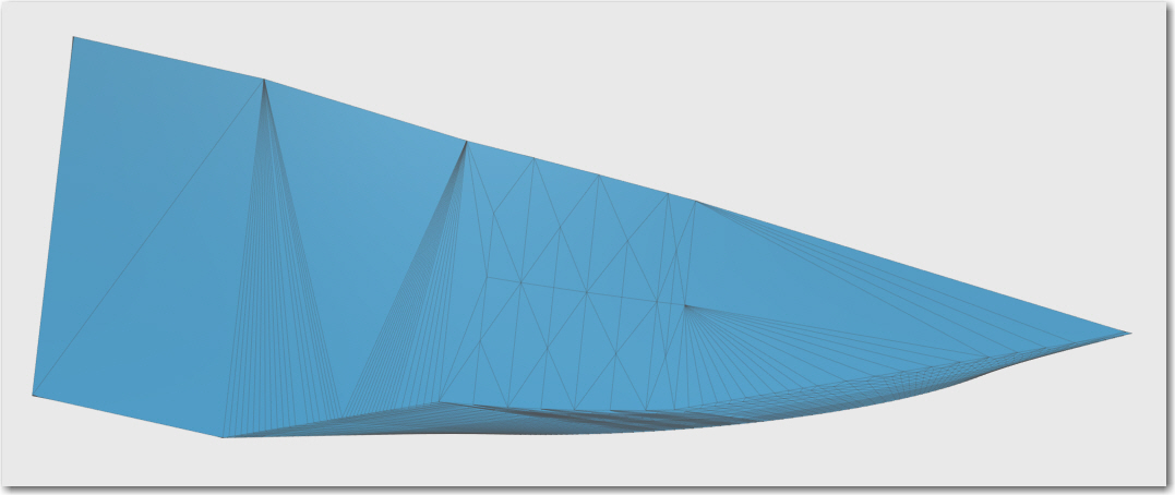
So now it was time to fire up my 3D printer and start making parts. Unfortunately, in the interim between this version and the last one I had decided to do the long-awaited upgrade to a heated print bed so I could eventually transition to stronger and more resilient ABS plastic instead of only PLA. The downside to a heated print bed is the much higher power requirements, and a host of other secondary problems associated with heated-bed printing. As it turned out, I couldn’t get a consistent print of the caddy piece with ABS or PLA using the heated bed, so I eventually had to downgrade my hardware setup and revert back to the original unheated bed, at least for these prints. The following screenshot shows the problem with PLA on the heated bed. The heat from the bed causes the PLA filament to stay soft too long and curl upward, even with forced air cooling.
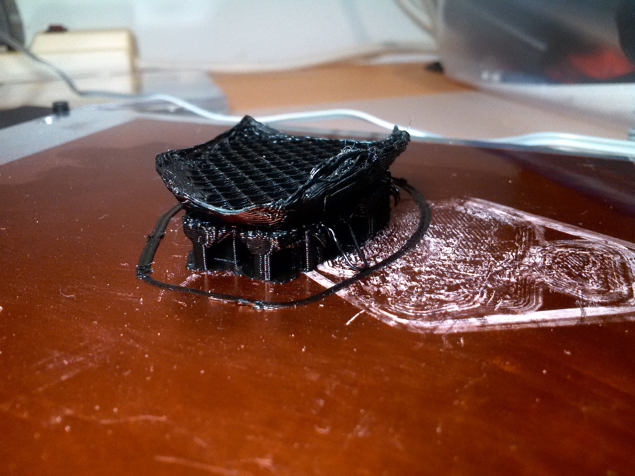
An aborted attempt at printing the remote caddy piece. Note the curled up edges and numerous print failures
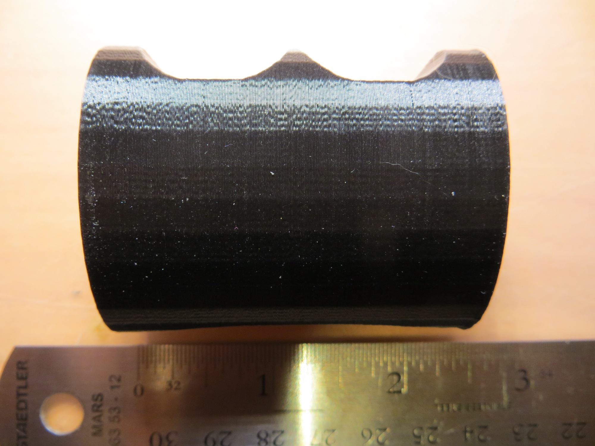
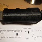
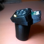
Anyway, after getting the hardware restored to its original unheated configuration, I started making trial prints of the remote caddy. The first several tries were failures for one reason or another. The first few trials failed because I had inadvertently disabled the ‘generate support structures’ option, and the next few failed because the support structures, when enabled, were too tightly bound to the main structure to remove when the print was finished! It took some tweaking and print re-orientation to get to a configuration that produced useful results, although I’m still not happy with the ‘final’ (see above) product. After the caddy piece, the flap grip piece was “a piece of cake”, as its geometry was much less complicated, although physically much bigger. The final caddy piece took about 1.5 hours to print, while the flap grip piece went for more than 4 hours!
-
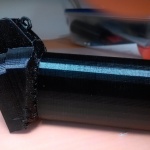
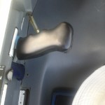
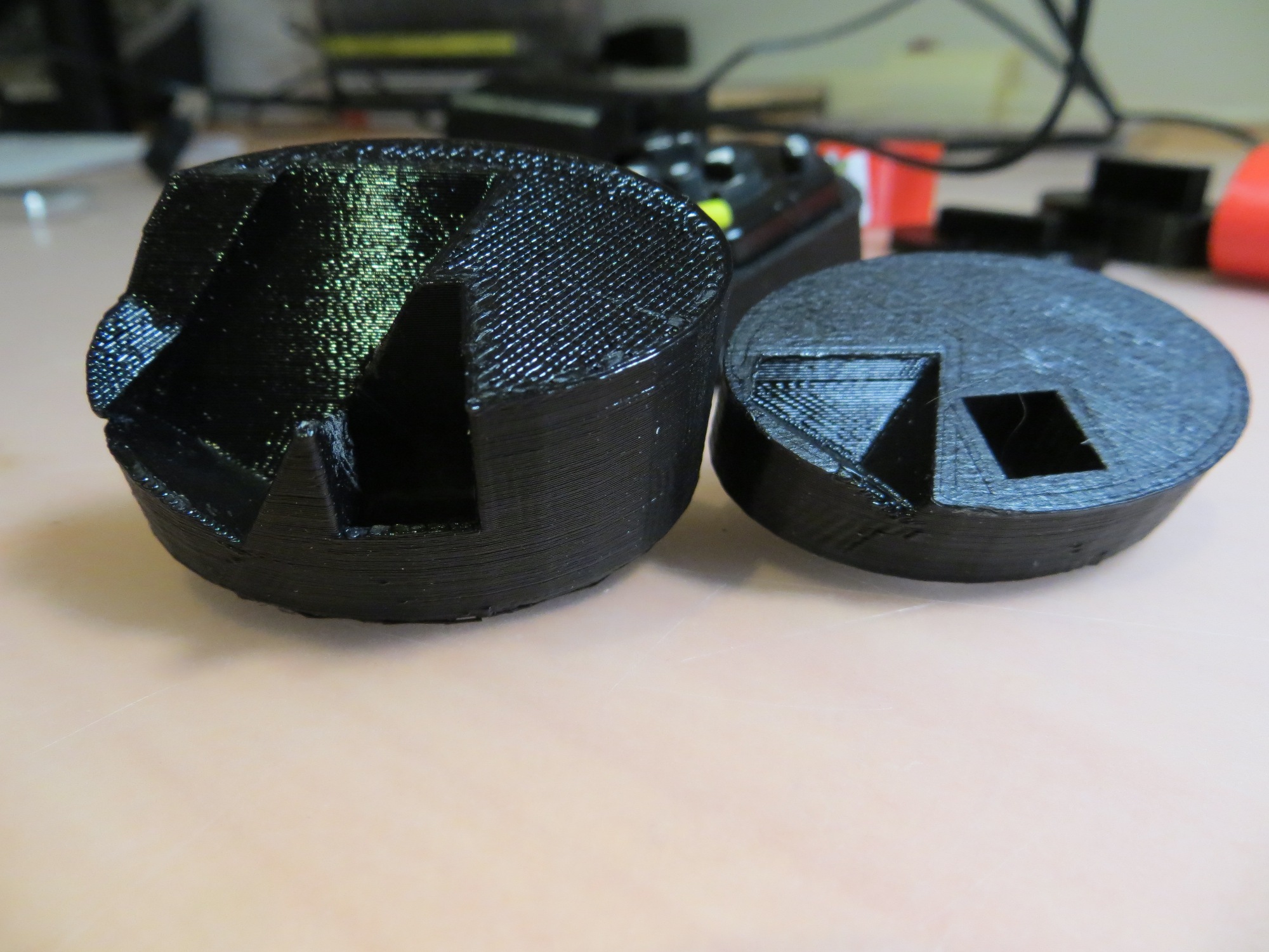
- Note the tie-wrap mounting loop on the underside of the caddy piece
-
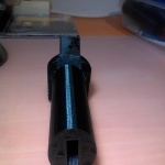
- View showing the rectangular slot for the flap control bar
-
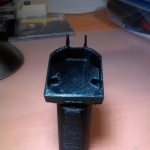
- This view shows the holes meant to accommodate the original mounting screws for the remote (didn’t work)
-
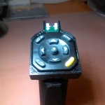
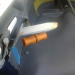
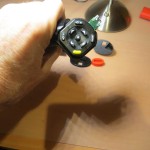
- Rear view with the remote installed
-
- Front view with the remote installed
-
- Side view with the remote installed
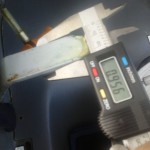
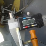
After getting both parts printed, there was still quite a bit of work to be done, especially on the caddy piece. As it turned out, the cylindrical post on the bottom of the caddy piece was much too long for the matching hole in the top of the flap grip (measurement goof on my part), so the post had to be cut down by hand. Then I had to drill and tap the post for a 4-40 screw so John can tighten the caddy down on the flap grip when he gets the rotation angle correct for his hand placement. Then a 4-40 clearance hole had to be put into the top of the flap grip piece, and the 4-40 screw threaded up into the rectangular slot, through the clearance hole, and then screwed into the caddy mounting post (let’s hear it for double-sided tape and long, skinny screwdrivers!). Also, the bottom surface of the caddy was a lot rougher than I liked (printer misconfiguration?) so I had to spend some time with a file and a sanding block to get this surface even remotely acceptable. I think I’ll try some more experiments to see if I can do a better job at this, so I’ll be ready when John comes back with the next batch of ‘issues’! ;-).
Stay tuned!
Frank