At the conclusion of Part 2, I had a finished design and a finished 3D part, which I sent off to my friend for evaluation in his glider. Unfortunately, the evaluation was – “It sticks up too high, and hits my stalk-mounted ClearNav unit” After going through some back-and-forth, he sent me some photos to illustrate the problem. The original rubber stick grip with top-mounted PTT switch just clears the bottom of the ClearNav (CN) unit, so anything higher than the original is going to be a problem. The finished grip I created based on the clay model was, unfortunately, about 2″ too high :-(.
So, back to the drawing board. I tried a ‘shorty’ version of the original grip, but that only got me about 1″ of the needed 2″ or so height reduction, so that was out. Then I decided to throw the entire clay model derived design out the window, except for just the CN remote caddy portion, and start over from there. The problem with the original clay model design was that it was slanted in such a way that it could not slip all the way down onto the stick, so I decided to start with a simply cylindrical grip that would slide completely down onto the stick, and then somehow tack the CN remote caddy onto the front.
Cockpit photos showed that the vertical portion of the joystick was about 4″ long, including the trim release trigger, so I started with a cylinder of a little over 100mm. This cylinder would house the hole for the stick, so it would obviously have to be bigger than the stick diameter of 25mm, plus some additional wall thickness. How much bigger? I decided make it just big enough to completely sever the CN remote caddy portion from the rest of the ‘finished’ grip derived from the clay model. I started this process in TinkerCad by placing a cylindrical ‘hole’ in the model, and increasing its diameter until it just stuck out of both sides of the model at the neck, separating the front and back halves. This required a cylinder diameter of 35mm, as shown below.
-
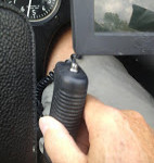
- Original aircraft stick grip. Just clears the ClearNav
-
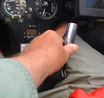
- Aircraft joystick without the grip, showing clearance to ClearNav
-
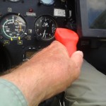
- ‘Shorty’ grip version. Still too tall
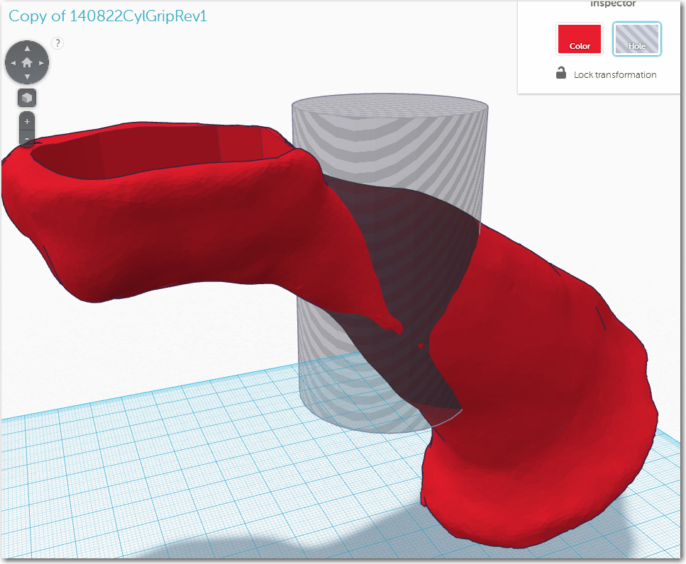
Separating the CN remote caddy from the rest of the grip
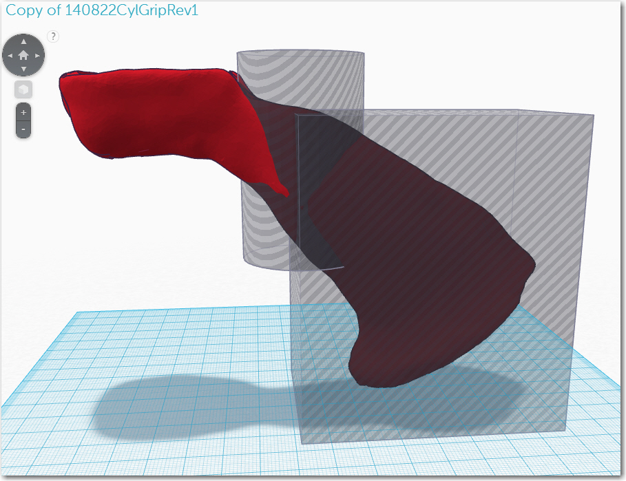
Removing the rest of the grip from the design
After that, I added a rectangular ‘hole’ to remove the now-separated back half of the grip, leaving only the CN remote caddy portion with a 35mm-diameter arc in the back. Then I simply added a 35mm diameter solid cylinder to the design in the same place as the ‘hole’, and of course this cylinder fit perfectly into the arc made earlier by the 35mm diameter ‘hole’. The only thing left to do was to ‘drill’ a 25mm hole into this grip cylinder, leaving a 5mm wall on the sides, and a 3mm wall at the top. Assuming this grip arrangement was seated fully on the stick, then it should stick up no more than 3mm from the top of the stick itself, or less than the height of the original grip plus PTT switch.
-
- Top view showing CN remote caddy details
-
- Side View
-
- Side view showing trim trigger cutout and bottom of remote caddy
This design is nowhere near as elegant as the clay model derived one, but it should work as a practical starting point for a design that actually works – the elegance can come later!
As a side note on all of this, the process of going from the original design to the ‘cylindrical grip’ design was very interesting because it is completely and utterly different than normal design practices. Instead of building another design up from scratch, I was able to add just two ‘holes’ and one hollow cylinder to the original design to come up with something completely different. In TinkerCad, you can add and combine solid parts, but you can also remove material by adding ‘holes’. Every primitive in TinkerCad can be used as either a solid object that adds material to the design, or as a ‘hole’ that removes material from the design. Moreover, portions of a design removed by holes don’t get removed until grouped with that hole. Material that is removed via the addition of a hole isn’t really deleted – it is just ‘hidden’ by whatever combination of holes negates its presence (exporting the design as an STL file and then re-importing it into TinkerCad does, in fact, permanently remove all ‘holed’ portions of the design). This process leads to some bizarre and counter-intuitive results, as it the order in which holes and solids are grouped determines the final visible result. In a complex design, it is quite possible to wind up with an unexpected result, because the grouping order got changed somewhere along the way. If the grouping error occurs down inside the design, then it might not get noticed until the 3D part is printed, and a hole that was supposed to be there isn’t, or some material that wasn’t supposed to be there suddenly reappears!
OK, so this design will go off to my friend tomorrow for yet another clash with reality. Hopefully this one will be a little closer to usable, and maybe point the way toward a final product – we’ll see!
Frank