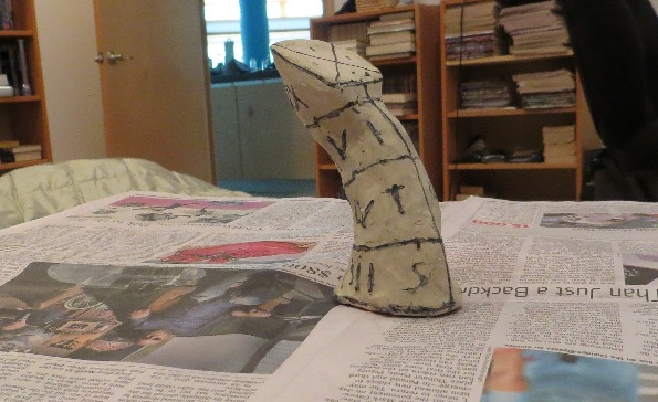
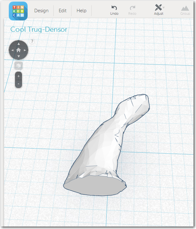
At the conclusion of ‘Part 1 – From Clay Model to TinkerCad’, I had finally managed to get a decent 3D model into TinkerCad as a binary STL file. Now the challenge would be to transform that blank template into something that could actually be printed on my PrintrBot and used in a real glider aircraft. To get from where I was to where I wanted to go required the following steps:
- Modify the joystick top to accept a ClearNav remote controller
- Design in the the ability to install a separate switch, for use either as a ‘climb/cruise’ vario switch or as a separate ‘push-to-talk’ (PTT) switch (the ClearNav stick-top remote controller accessory has it’s own integral PTT switch, but…).
- Create a 1″ diameter hole to mount the joystick onto the glider joystick handle/tube
- Create a wiring passageway up to the top of the joystick
- Print it out on my PrintrBot Simple Metal.
Modify the top to accept a ClearNav remote controller
This step appeared to be the hardest and most critical part of the design, so I decided to tackle it first.
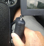
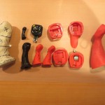
Of course, a fundamental part of this step required that I have precise dimensions for the ClearNav stick-top remote controller, and this turned out to be rather more problematic than I had expected. ClearNav, Inc didn’t have any technical specifications for the part on its website, and the support crew there couldn’t provide anything either. The president of the company promised to send me a 3D design of a blank controller part as an STL file, but never delivered anything, even after multiple inquiries. Fortunately, I had a hand-held remote controller left over from my previous life as a glider pilot, and I happened to know that the outside dimensions of the stick-top and hand-held controllers were identical. The difference was that the stick-top remote has an extra button to replace the normal PTT button, and the hand-held controller does not. Another non-relevant difference is that the hand-held remote has a telephone-style RJ-45 connector, while the stick-top version uses a wire pigtail.
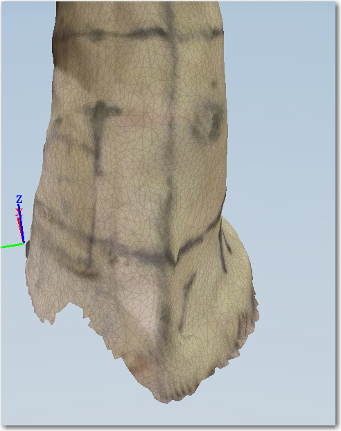
So, I was able to use my hand-held controller to produce a blank 3D model for sizing the stick-top cavity. I started out with a blank that was as precise as I could make it, and then oversized it by about 1mm in all dimensions to use as a ‘hole’ in the design.
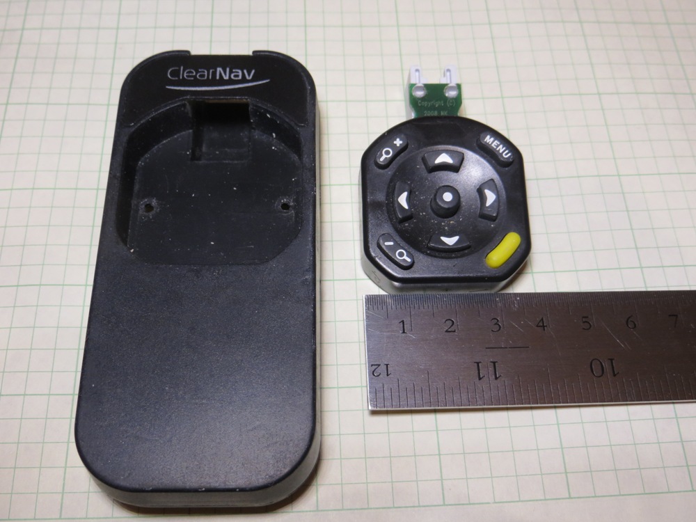
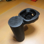
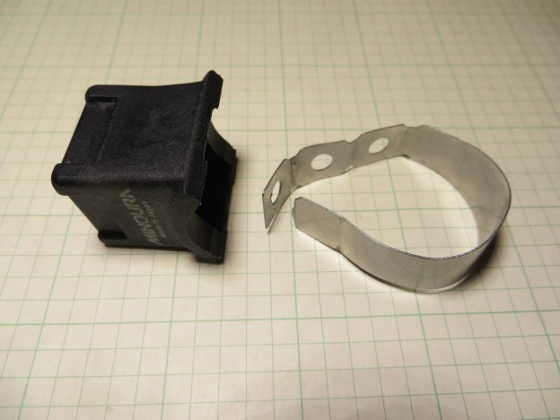
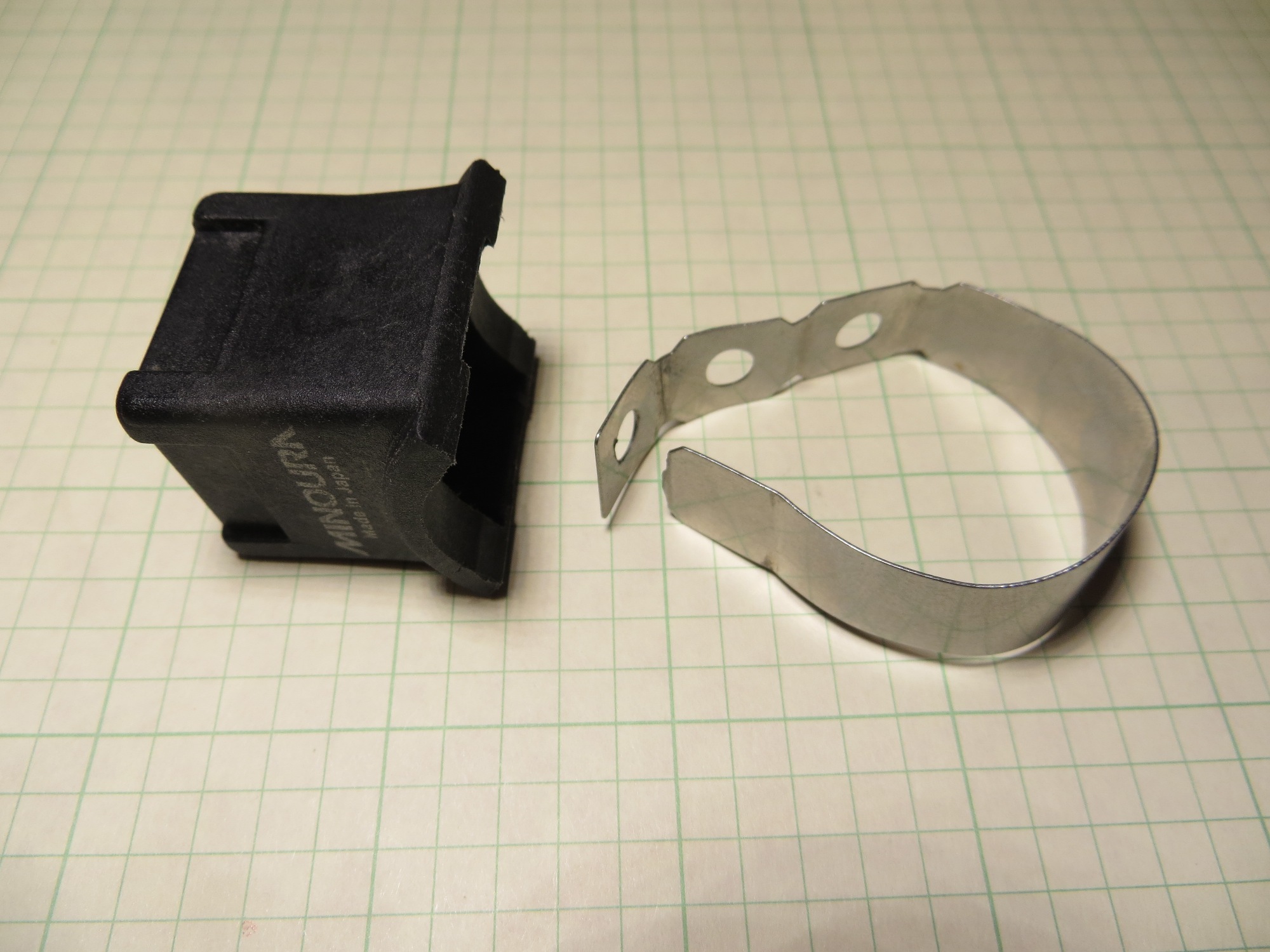
Disassembled Hand-held ClearNav Remote
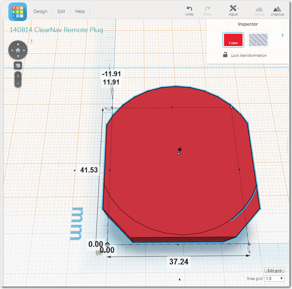
Slightly oversized blank for joystick ClearNav remote cavity
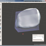
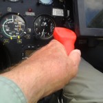
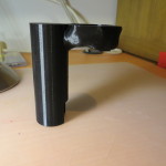
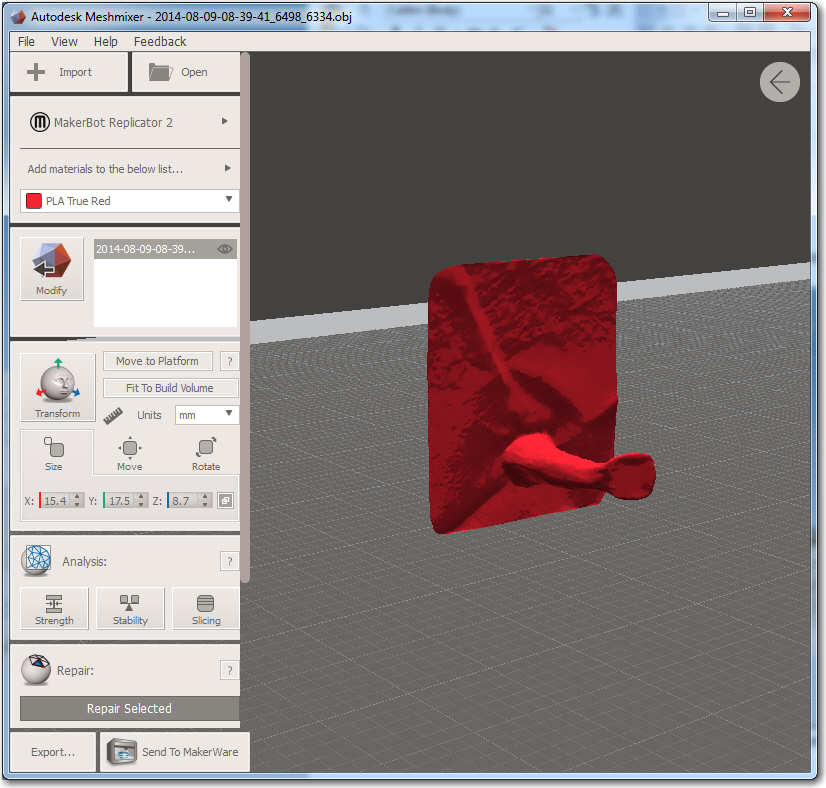
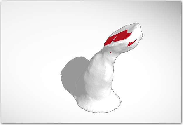
Then I started trying to fit the blank into the top of the joystick, with very limited success initially.
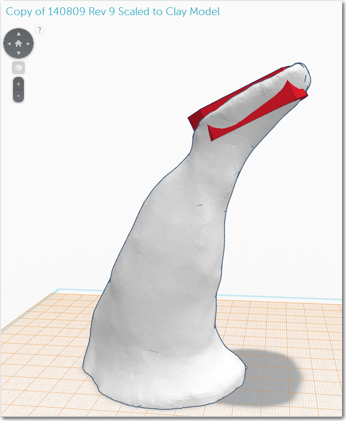
First attempt at fitting the ClearNav remote into the top of the joystick
The thickness of the 3D representation of the clay model just wasn’t sufficient to contain the volume of the ClearNav remote, no matter how I moved it around. So, back to the drawing board (literally!).
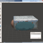
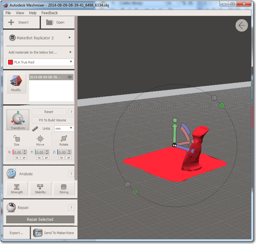
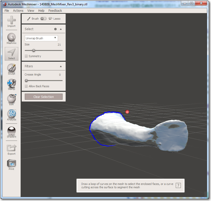
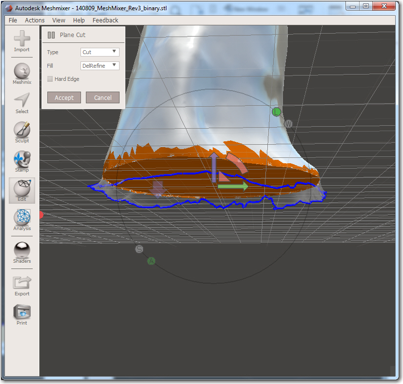
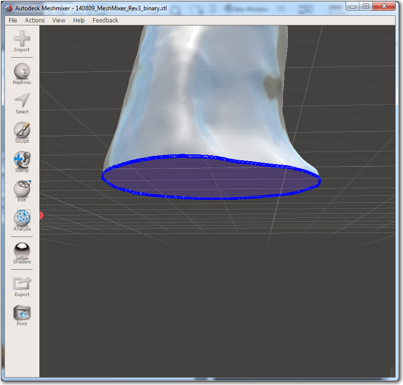
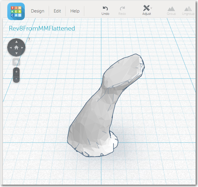
I did some more research, and taught myself how to use MeshMixer’s ‘Inflate’ sculpting brush to add some bulk to the top of the joystick, and the ‘Flatten’ brush to slim and smooth the neck area. After several back-and-forths between MeshMixer and TinkerCad, I arrived at a version that would indeed contain the remote.
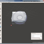
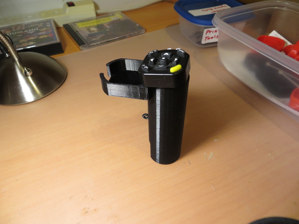
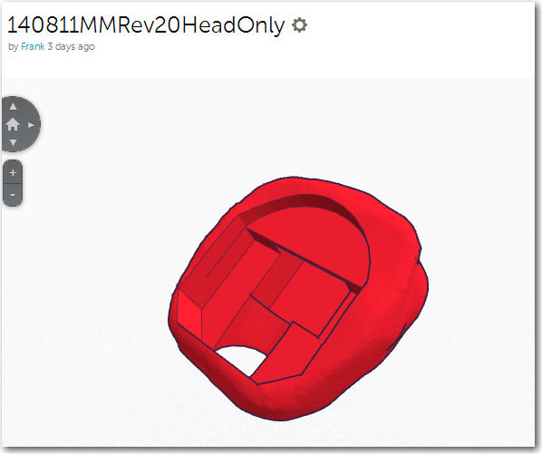
Close, but no cigar!
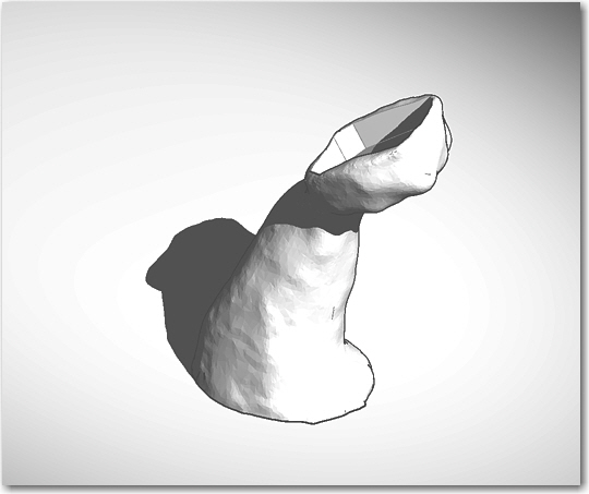
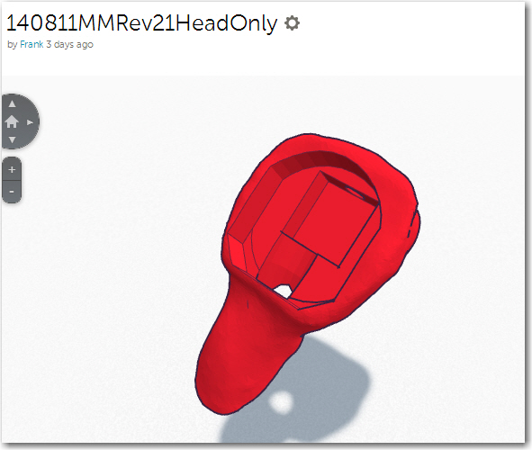
Remote is completely contained now in the joystick. Note the neck has been slimmed down as well
Design in the the ability to install a separate switch.
The typical cross-country glider uses a boom microphone and a stick-mounted push-to-talk (PTT) switch for radio communications, and there is often at least one more switch (typically a SPDT toggle) mounted on the forward surface of the stick top. The stick-top ClearNav takes over the real estate used by the original PTT pushbutton, but cleverly replaces it with an integrated PTT switch on the remote itself (this integrated PTT button isn’t on the handheld version). However, I still needed to make room for the front-mounted SPDT switch.
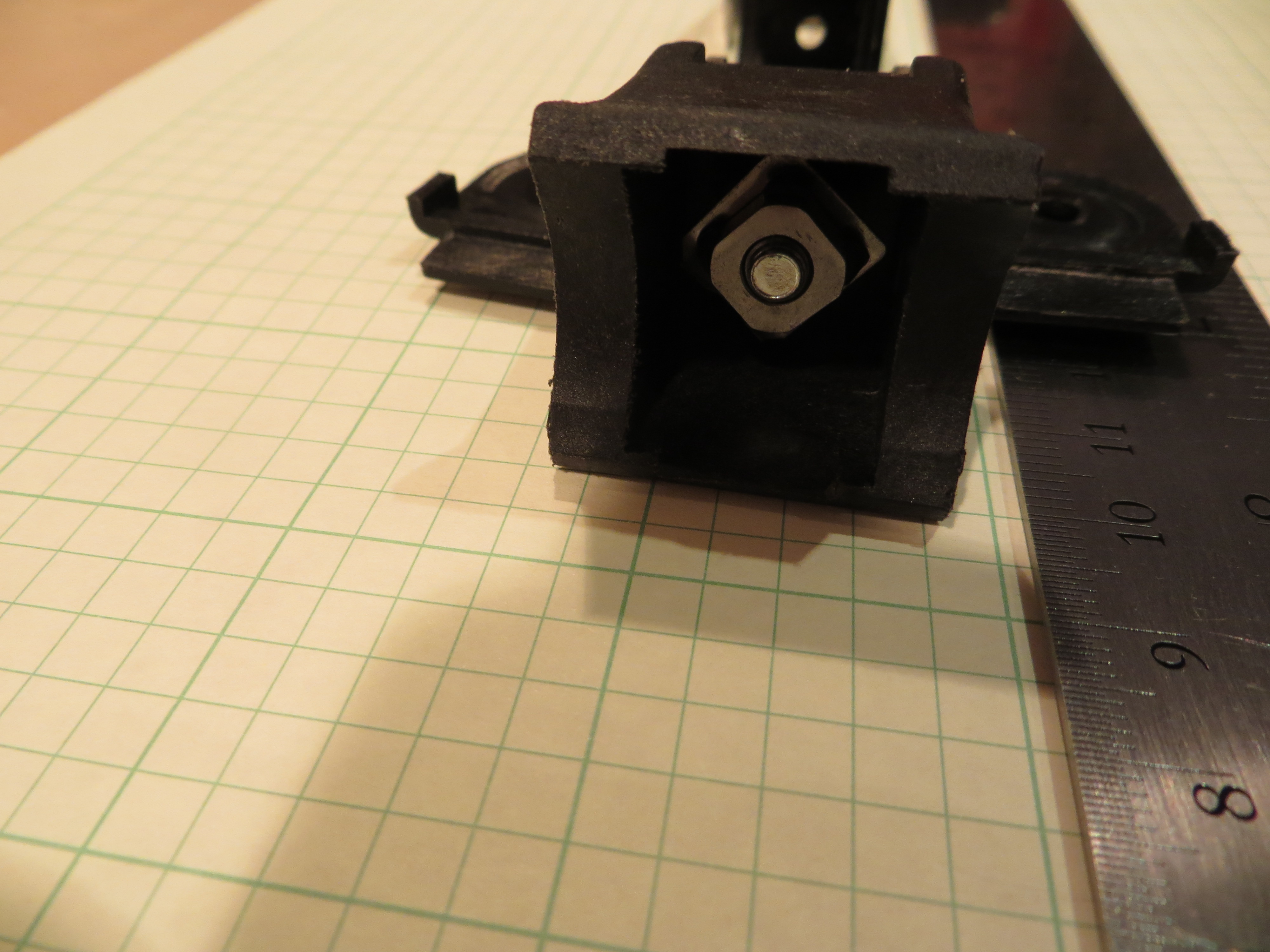
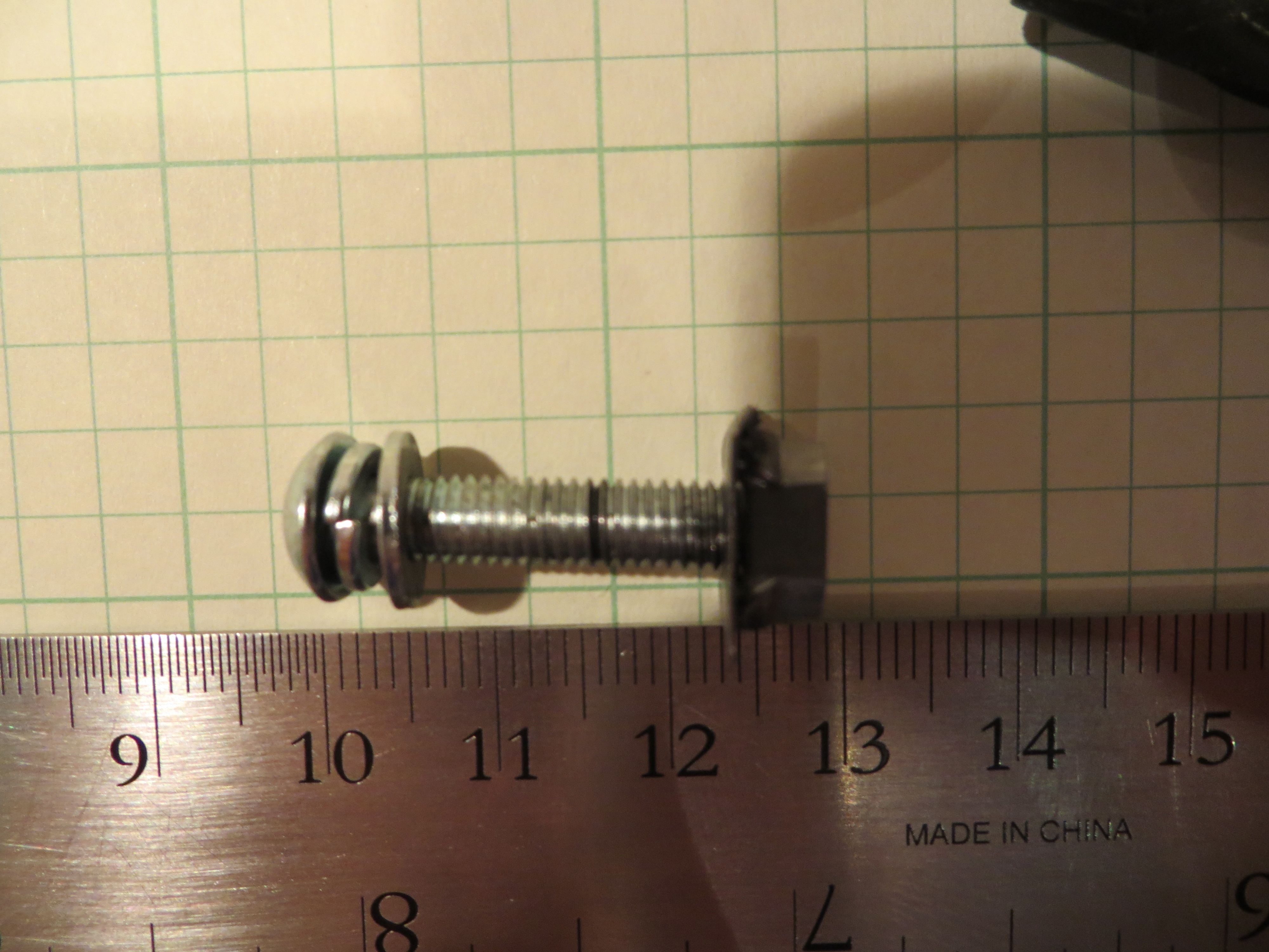
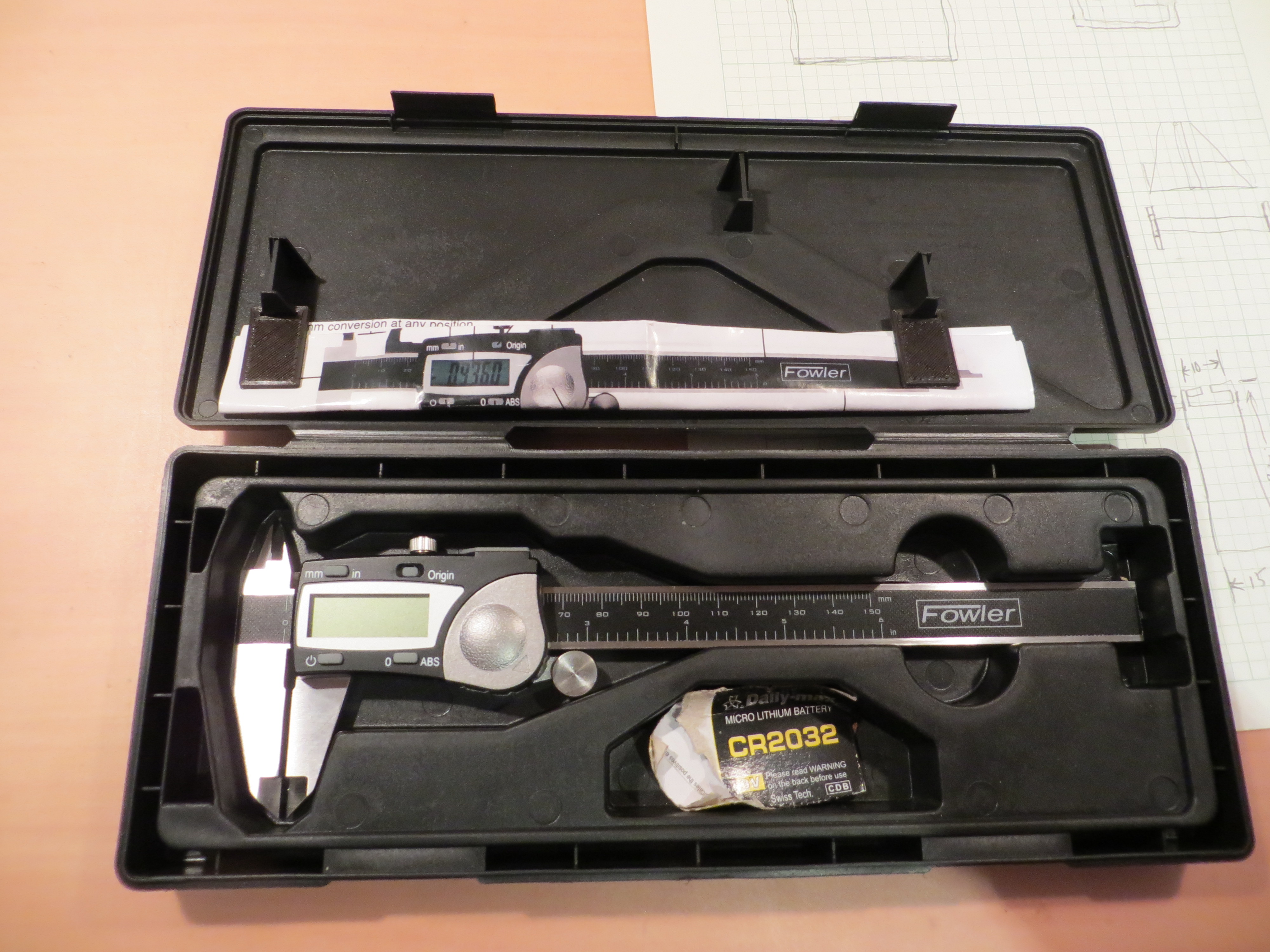
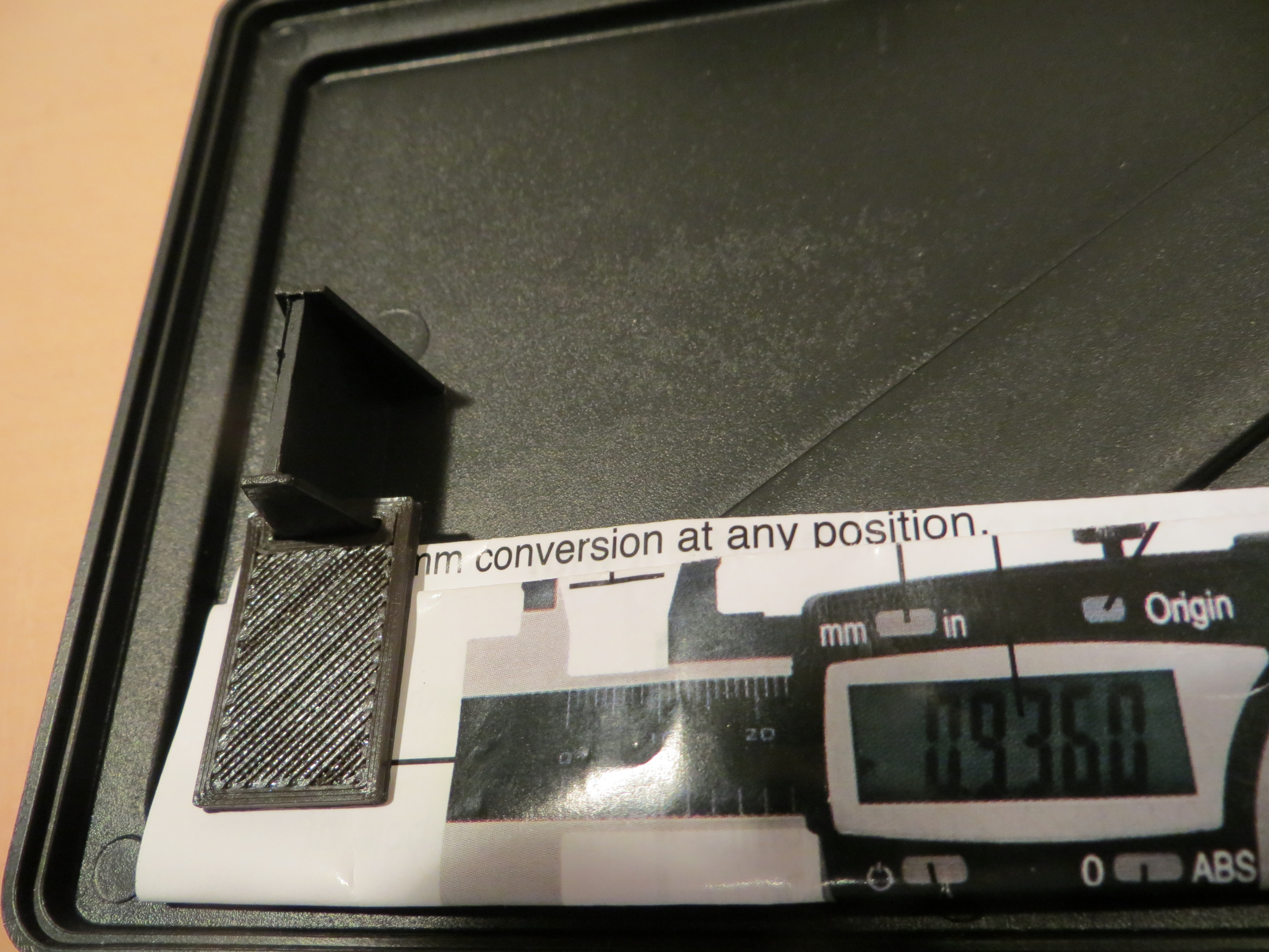
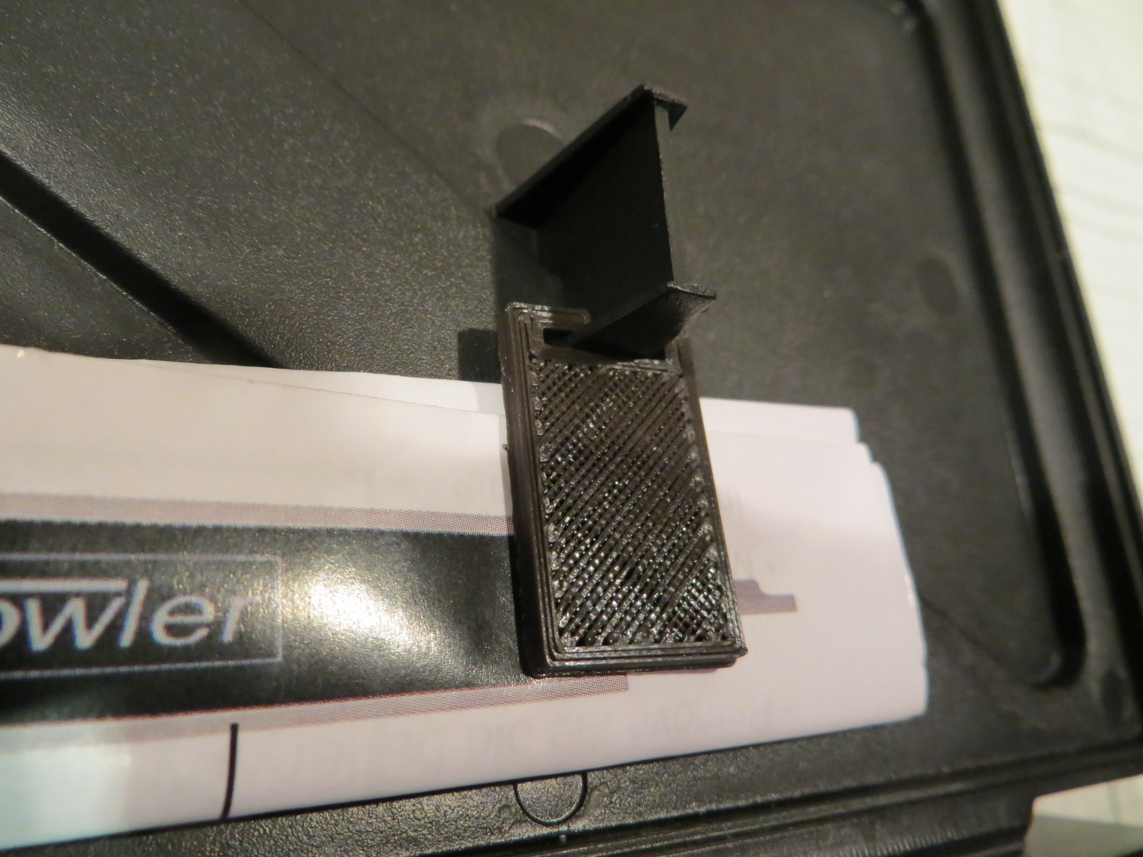
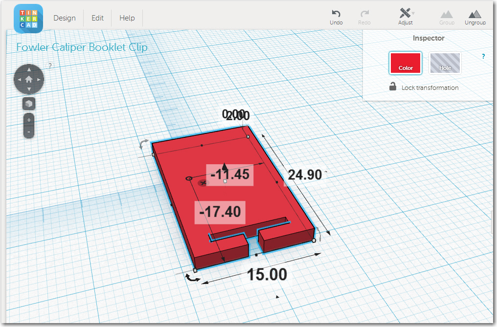
The first step in this portion of the design was to create a 3D model of a ‘subminiature’ SPDT switch. Fortunately I happened to have one in my design shop, left over from an even earlier lifetime as an electrical design engineer. Now that I have my high-quality Fowler calipers from McMaster-Carr, it was a snap to measure the switch and create a fairly accurate 3D model in TinkerCad.
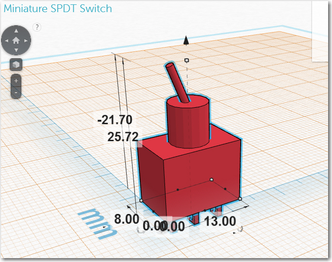
Subminiature SPDT switch model
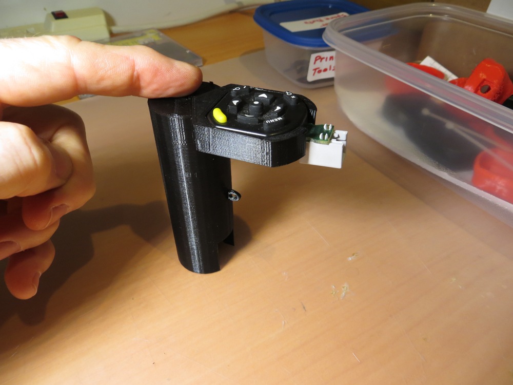
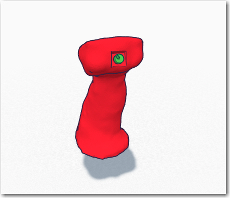
Once I had the switch, I was able to figure out how to shoehorn it into the top of the joystick, in a forward-facing orientation. This took a while, and involved creating a smaller ‘sub-basement’ cavity under the one created to accommodate the ClearNav remote.
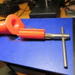
Create the 1″ diameter mounting hole and wiring passages
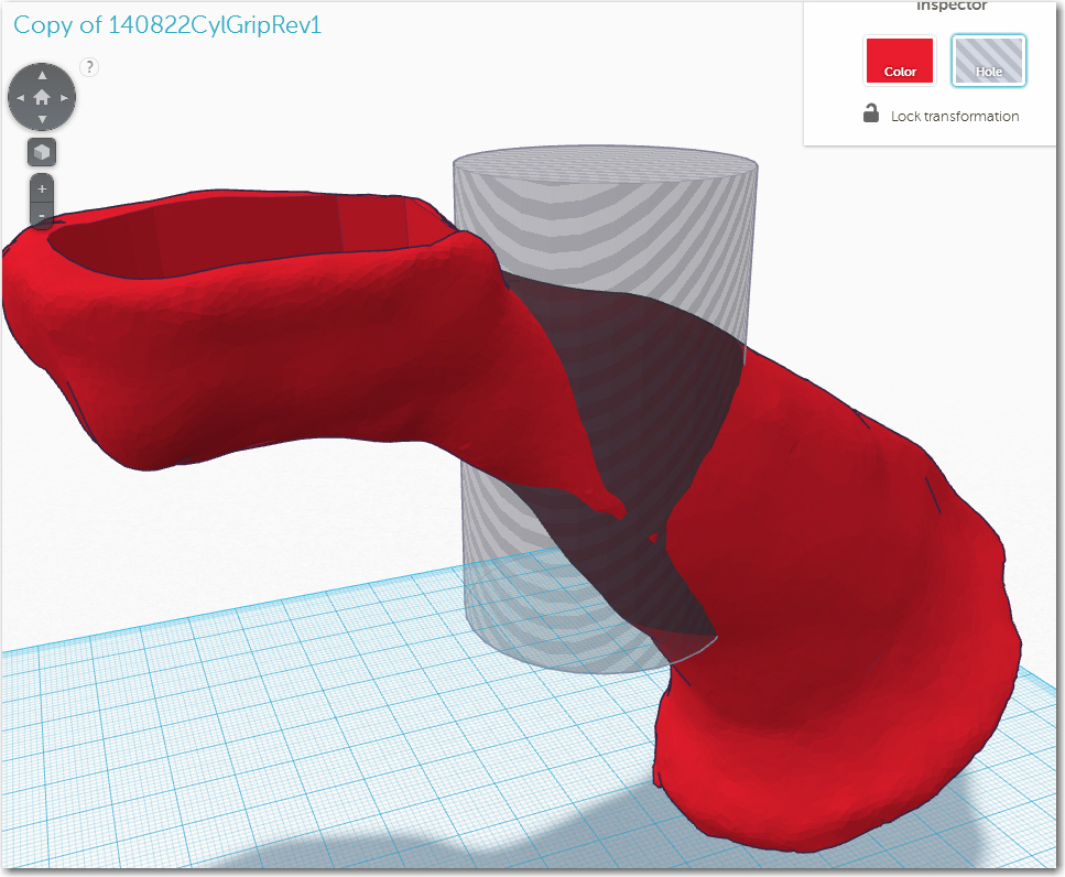
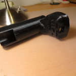
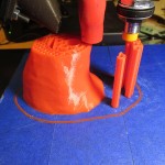
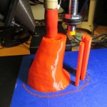
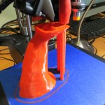
You’d think this would be the simple part – just a couple of cylindrical ‘holes’ added to the part and we’re done. Unfortunately, life (or joystick design) just ain’t that simple, and what I thought would be a ’10 minutes tops’ job turned into a multi-day headache, and finally into a fun piece of creative work. The initial 1″ diameter hole wasn’t too bad, but since the joystick body isn’t particularly symmetric, it wasn’t (and still isn’t really) clear where the hole should go. I finally opted for the placement that would allow the hole to penetrate the farthest up into the joystick body, as that would result in the widest range of mounting options in the actual aircraft. Then I created a smaller diameter angled cylinder to connect the vertical hole to the top cavity, to act as passage for the necessary wiring.
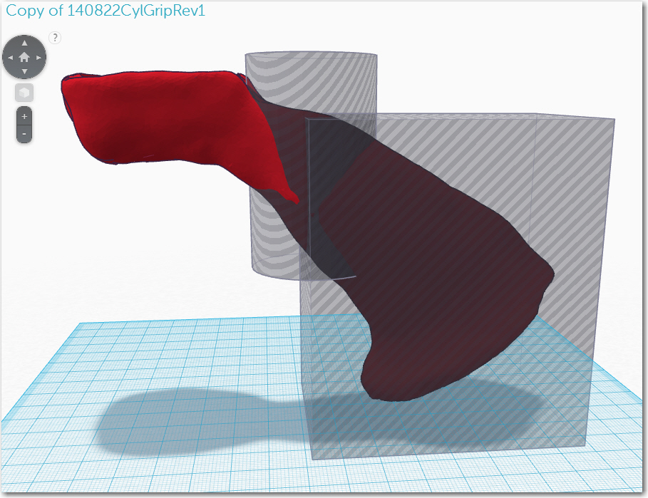
This seemed to be working really well, until I printed a couple of half-scale models and discovered that both the vertical and slanted cylinders poked through the side of the joystick, even thought the TinkerCad model showed some material thickness all the way around. I was trying (and failing) to figure out how this could possibly happen when my wife, who knows nothing about 3D printing, pointed out that the minimum printable wall thickness stays the same regardless of scale, so something that shows 2-3 min thickness walls at full scale might not be even one min wall thickness at half-scale – oops!
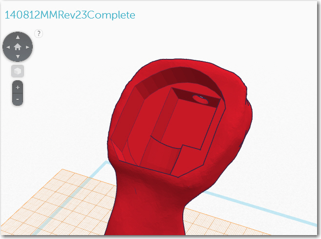
OK, back to the drawing board. I played around with this forever, but finally concluded that I was going to have to give up on the linear passageway idea, and go with something curved if I wanted to have decent wall thickness all the way around the passageway for its entire length from the top of the 1″ mounting hole to the cavity at the top of the joystick. To make this work, I used TinkerCad’s ‘Torus’ primitive, and adjusted the torus diameter and cross-section to get what I wanted. When everything looked right, I used several rectangular ‘holes’ to cut off the sections I didn’t need.
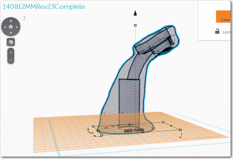
Final version, showing the 1″ vertical cylinder for joystick handle mounting, and the curved wiring passageway
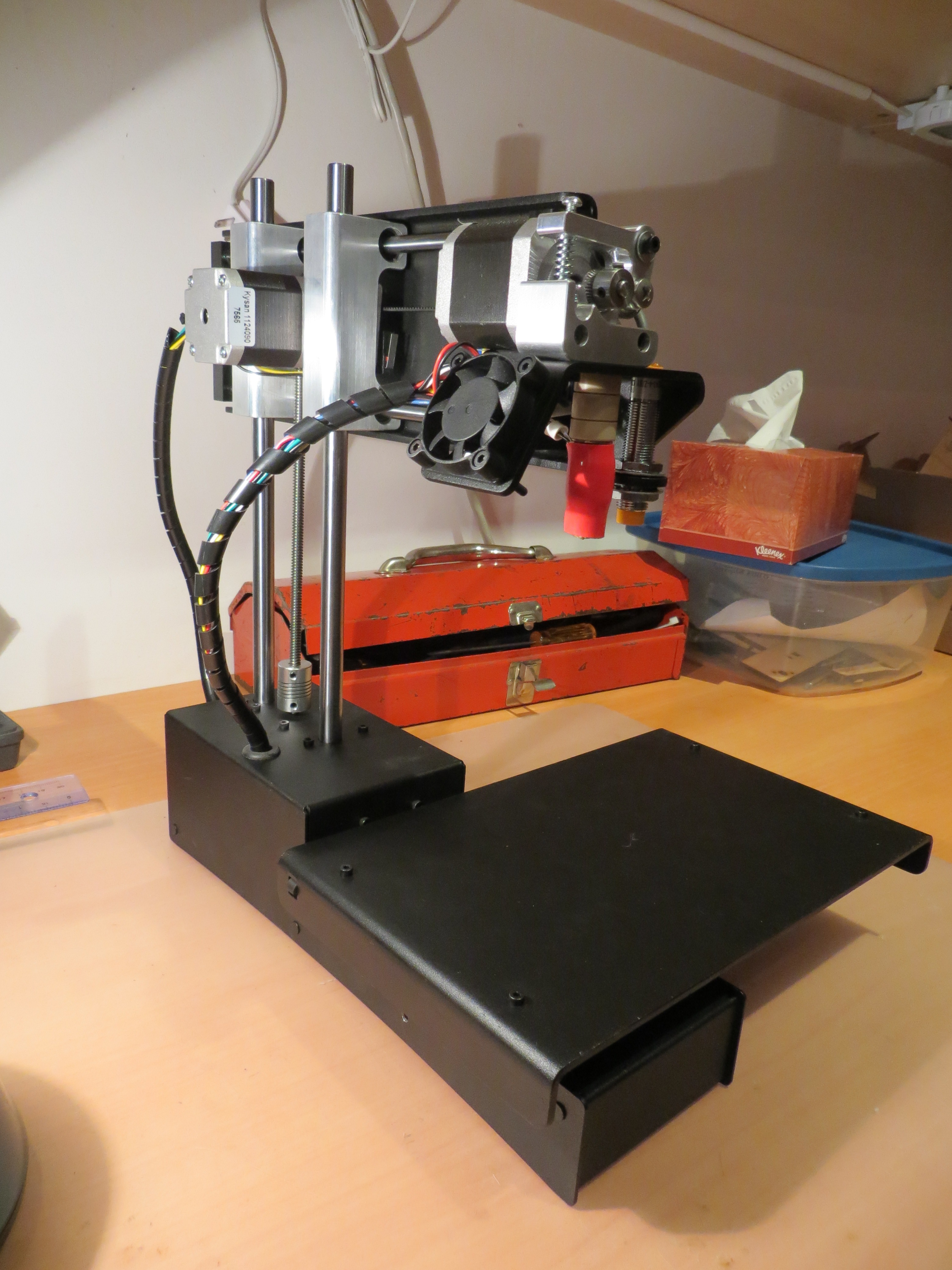
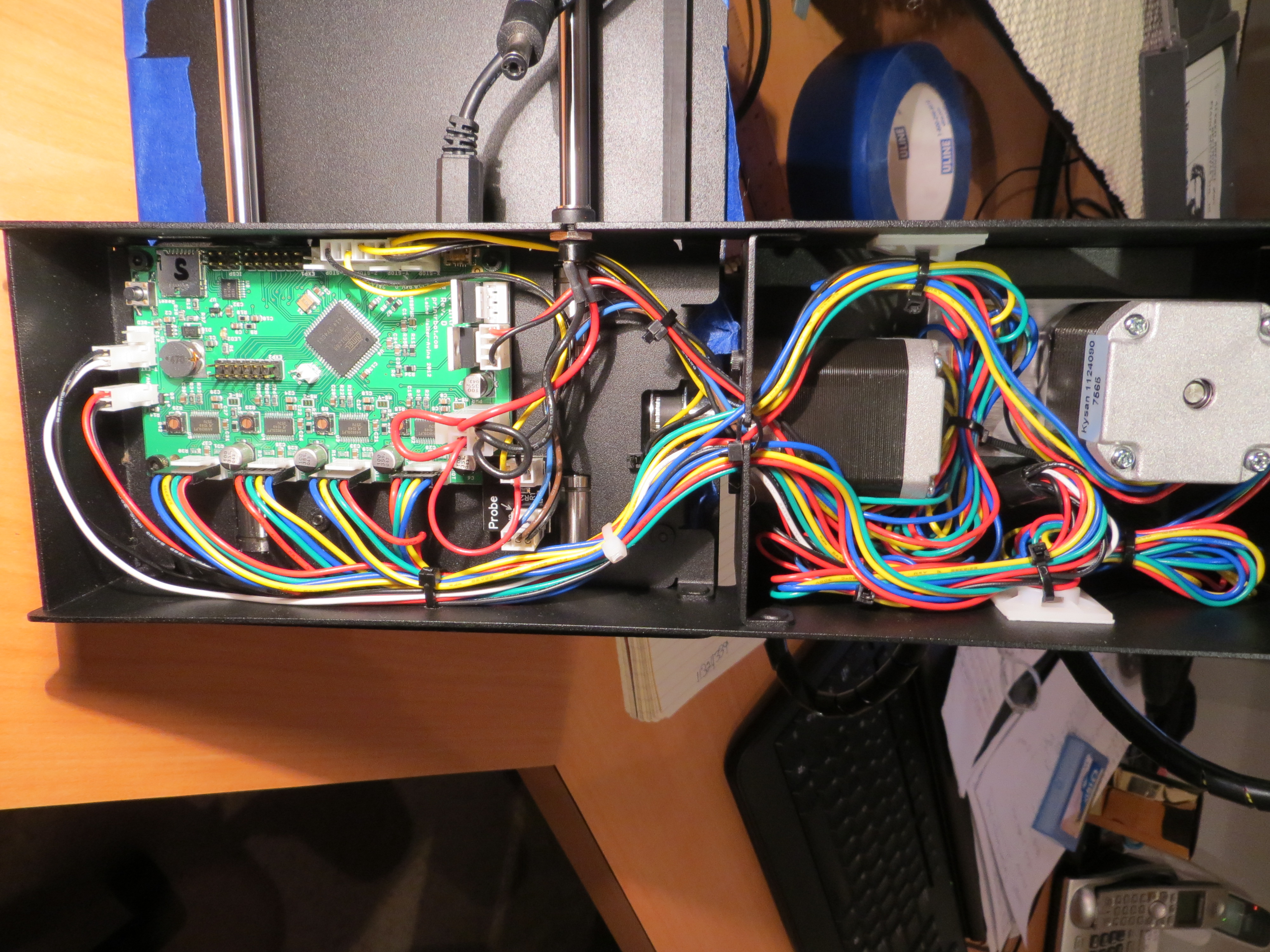
Printing on my PrintrBot Simple Metal
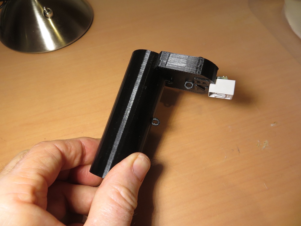
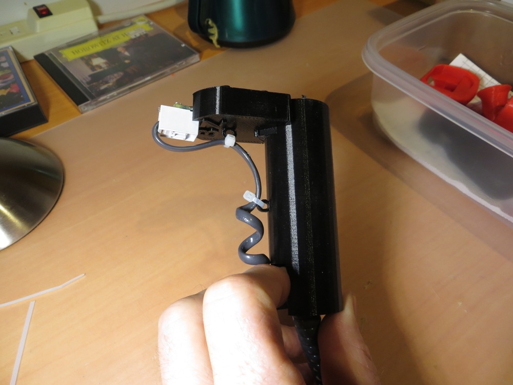
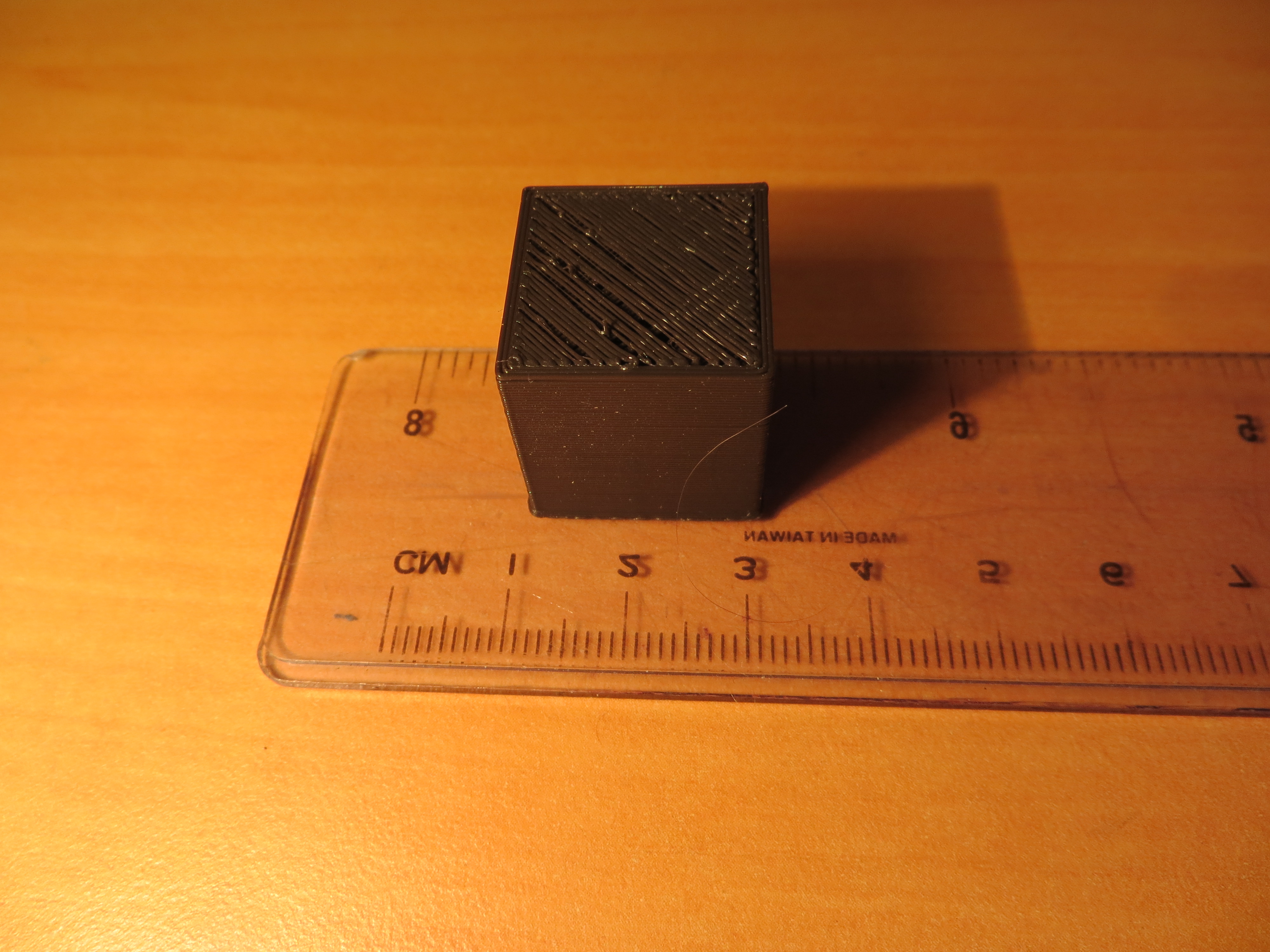
After verifying this hole structure via a half-scale model, I was ready to step up to full scale testing. However, I really really did not want to pay the time and filament cost for multiple full scale prints, so I decided I would just print the top of the model to verify all the cavities at full scale. Since none of the hole structures poked though anymore at half scale, I was pretty confident they wouldn’t at full scale. So, I made a series of full scale prints of just the top portion, and these caused me to make some adjustments in the auxiliary SPDT switch cavity and mounting arrangements. With these partial full scale prints, I was able to use the actual full scale real-world parts (ClearNav remote and subminiature SPDT switch) to check for fit and clearances.
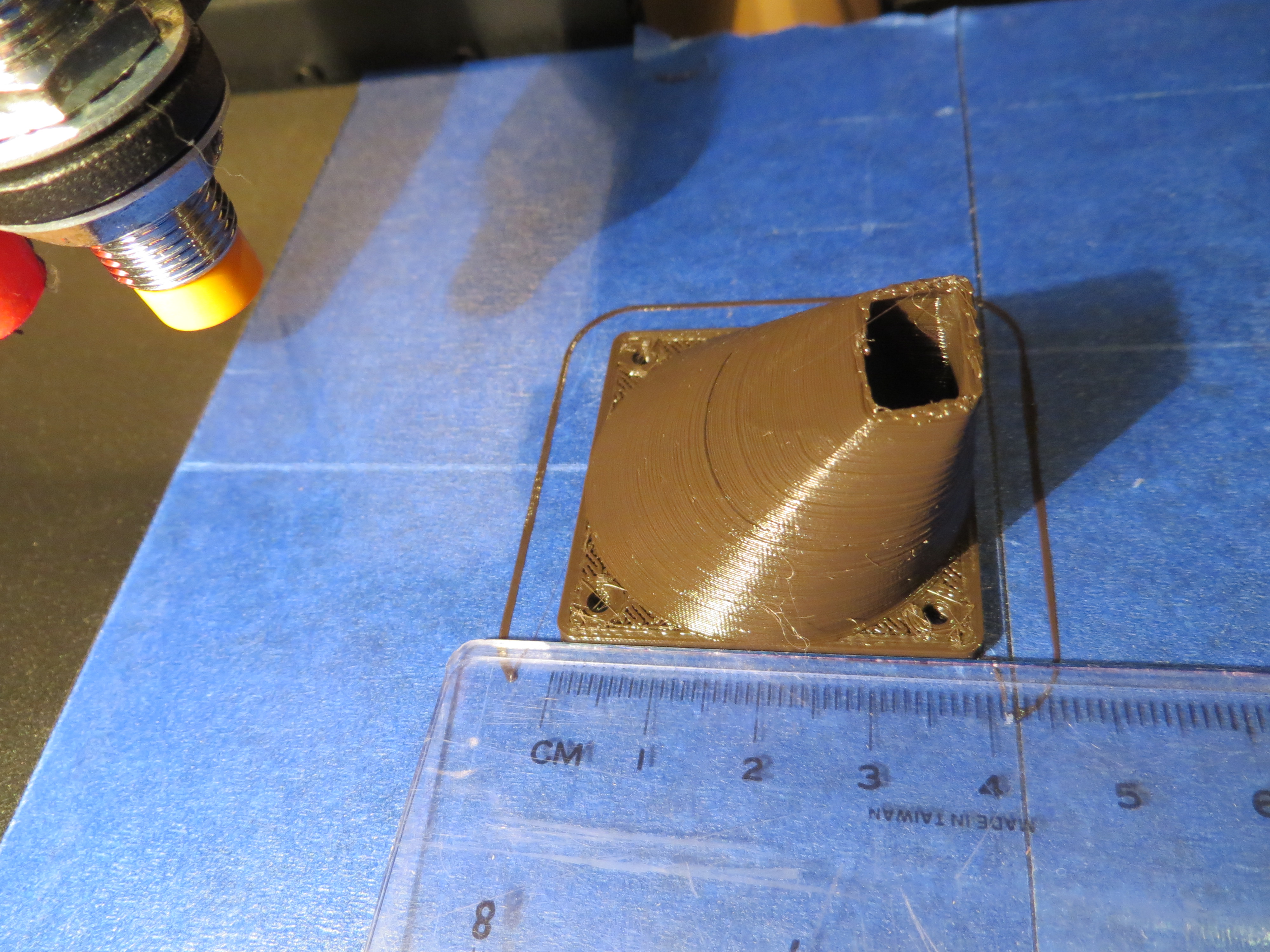
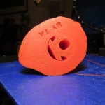
First full scale print of just the top cavity structure. Note the top part of the cavity is incorrect.
Second full scale print of the top cavity structure. Note the top portion of the cavity has been corrected.
Final version of the joystick top cavity structure. This just required a slight resizing of the cavity to accommodate the actual full scale ClearNav remote, and the actual full scale SPDT switch.
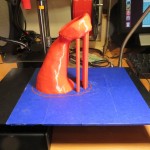
After the full scale partial printouts, I was ready to go for a full scale print. The overall height of the joystick (121.6 mm or 4.8″) would be close to the 6″ maximum for my PrintrBot, so I was a bit worried that bad things were going to happen. Also, since this was to be such a long duration print, I was worried about filament jams and all the other things that could go wrong on a long print. As it happened, the print went off without a hitch, and produced a near-perfect model.
-
-
Just getting started…
-
-
Neck and neck 😉
-
-
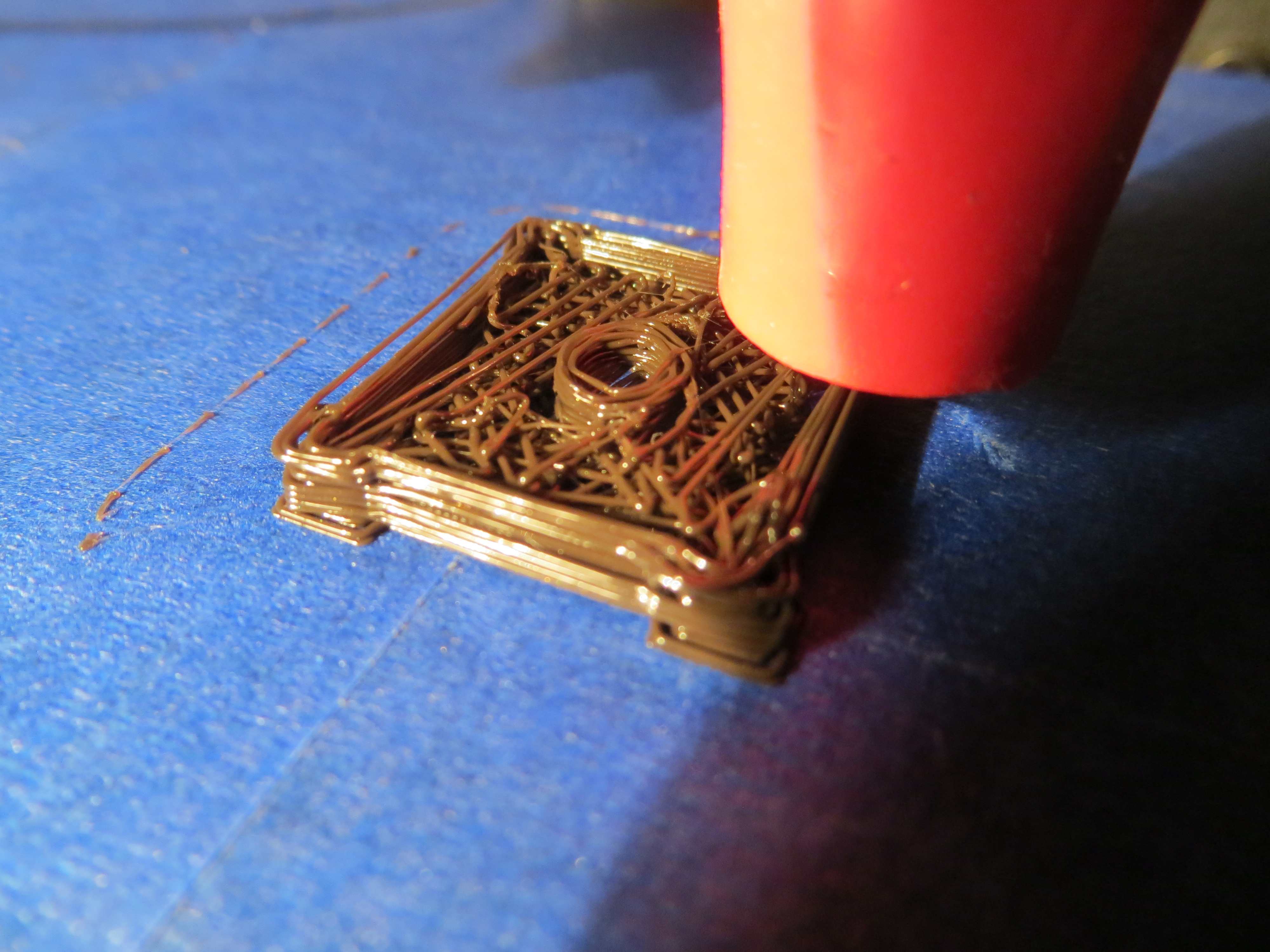
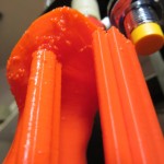
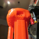
Starting the ClearNav Remote cavity. Note the small bubble imperfections
-
-
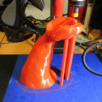
View of the support structure, and more detail on the bubble defects
-
-
Almost finished…
-
-
Finished!
-
-
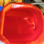
Interior view of remote controller cavity, with some support structure still visible
-
-
View of the aux switch cavity, with support structure and bubble defects visible
-
-
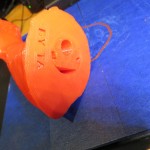
View of the bottom with central hole support structure and author signature
-
-
Another view of the bottom hole
-
-
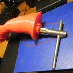
Removing the central hole support column with a hole reamer
-
-
Central hole support column removed
-
-
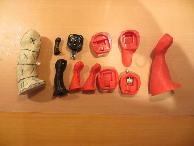
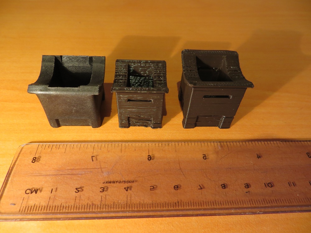
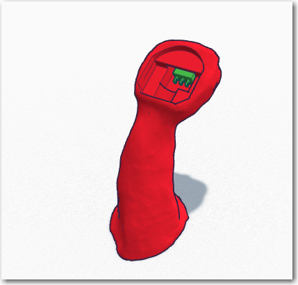
The joystick evolution, from the clay model on the left to the finished 3D print on the right
Summary and Lessons Learned
- Although I much prefer to have a ‘real’ project as a motivator when learning a new software package or skill, I probably overreached a bit with such a complex project so early in the learning curve. Learning how to capture a 3D model from photos, how to use MeshMixer’s sculpting tools, advanced TinkerCad techniques, and a challenging print size and overhang configuration all rolled into one project!
- The combination of the Autodesk suite of 3D applications (123d Catch, 123d Design, MeshMixer, and TinkerCad) forms a very complete and rich design suite for capturing a 3D object in a form suitable for further development and eventual 3D printing. The fact that all of these applications are (at least for the moment) entirely free is amazing!
- the 3D capture and design application world is changing and evolving at warp speed. All of the above apps have serious bugs, deficiencies, and internal inconsistencies, so staying light one’s feet is an absolute necessity. If it doesn’t work right now, check back tomorrow! In my case the 123 Catch application literally changed overnight – on day 1 I couldn’t seem to get my capture to stitch at all, and on the next it was all done automagically! The downside of all this is that skills and/or workarounds learned today may be irrelevant tomorrow, so the need for constant retraining is going to be a fact of life.
- As in other endeavors, success is 1% inspiration and 99% perspiration. I just kept banging away at the problem until it gave up and rolled over. It didn’t matter to me whether my progress was due to my brilliance or just sheer doggedness – either one was fine with me ;-).